1
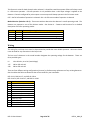
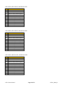
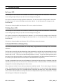
User Manual
DSP-21
Directional Counting Detector
Diablo Controls, Inc.
Copyright © 2014
Document:
DSP21_MAN_B
Released:
March 30, 2014
Pros Who Know Trust Diablo
1.
Contents
2.
Introduction........................................................................................................................................................3
3.
Technical Data ....................................................................................................................................................4
Functional Data.......................................................................................................................................................4
Electrical Data.........................................................................................................................................................4
Environmental Data................................................................................................................................................4
Mechanical Data.....................................................................................................................................................5
4.
Features and Functions ......................................................................................................................................6
Operating Modes....................................................................................................................................................6
Presence Detection.................................................................................................................................................7
Pulse Detection.......................................................................................................................................................8
Count Detection......................................................................................................................................................8
Sensitivity................................................................................................................................................................8
Sensitivity Boost .....................................................................................................................................................8
Fail-Safe vs Fail-Secure ...........................................................................................................................................9
Fail-Safe ..................................................................................................................................................................9
Fail-Secure ..............................................................................................................................................................9
Detector Reset........................................................................................................................................................9
Channel Reset.........................................................................................................................................................9
Indicators..............................................................................................................................................................10
5.
Installation........................................................................................................................................................13
Detector Installation.............................................................................................................................................13
Loop Installation ...................................................................................................................................................13
6.
Configuration....................................................................................................................................................16
DIP Switches .........................................................................................................................................................16
Wiring ...................................................................................................................................................................18
7.
Troubleshooting ...............................................................................................................................................20
No Power LED .......................................................................................................................................................20
Flashing Power LED...............................................................................................................................................20
A Channel LED Flashes Slowly (1 Hz) ....................................................................................................................20
A Channel LED Flashes Quickly (5 Hz)...................................................................................................................21
A Channel LED Shows Two Quick Flashes Once Every Two Seconds ...................................................................21
A Channel LED Intermittently Comes On / Stays On Without a Vehicle Present.................................................22
A Channel LED Will Not Come On With a Vehicle Present ...................................................................................23
8.
Factors Affecting Count Accuracy.....................................................................................................................24
Loop Configuration ...............................................................................................................................................24
Loop Placement ....................................................................................................................................................25
Electrical Interference ..........................................................................................................................................25
DSP-21 User Manual
Page 2 of 26
DSP21_MAN_B
2.
Introduction
The DSP-21 is intended to be an ‘all-in-one’ vehicle detector designed for the parking industry. The DSP-21
Detector was specifically developed for parking garage systems that need accurate vehicle count information.
This detector is designed to operate utilizing a dual inductive loop configuration typical in the parking industry.
The small package is powered by a high performance 16-bit microcontroller that does not skimp on
performance.
The DSP-21 Detector was designed to retrofit into existing locations that may require a detector upgrade.
Sophisticated algorithms offer plug-n-play operation when using one of the counting modes. Its multiple
operating modes allow it to fulfill many needs within the parking industry. This allows maintenance personnel
to carry only one detector to meet most, if not all, of their vehicle detection needs.
The detector uses an 11-pin relay socket for connections. The DSP-21 is available in several pin-outs to allow
easy retrofitting of existing detectors.
The distinguishing feature of the DSP-21 is its ability to count vehicles and determine their direction of travel.
But this is only one of four possible operating modes for the detector. The two mode select DIP switches allow
the user to configure the detector to the mode of operation that best suits the needs of the installation site.
DSP-21 User Manual
Page 3 of 26
DSP21_MAN_B
3.
Technical Data
Functional Data
Sensitivity:
Four sensitivities selectable for presence or pulse modes of operation.
Low
.50% ΔL/L
Medium Low .10% ΔL/L
Medium High .05% ΔL/L
High
.02% ΔL/L
Frequency Settings:
There are two settings per channel. The actual loop frequency is dependent on
loop circuit inductance. The detector uses a channel scanning technology to
minimize channel to channel interference.
Pulse Output:
150 millisecond on period followed by a 150 millisecond off period before the
next pulse can begin.
Response Time:
150 milliseconds
Vehicle Hold Time:
Approximately 1 hour for a vehicle detection of 1% ΔL/L.
Electrical Data
Loop Inductance:
20 microhenries to 1500 microhenries (including lead-in inductance)
Operating Voltages:
Three power versions
10.5 volts to 30 volts AC or DC with over voltage protection
100 volts to 135 volts AC
200 volts to 270 volts AC
Operating Current:
10-30 volts DC/AC - 65 milliamps maximum. 50 milliamps typical.
100-135 volts AC - 30 milliamps maximum. 25 milliamps typical.
200-270 volts AC - 15 milliamps maximum. 12 milliamps typical.
Output Relay Rating:
3 amps @ 125 volts
Environmental Data
Operating Temperature:
-35°F to 165°F (-37°C to 74°C)
Storage Temperature:
-40°F to 176°F (-40°C to 80°C)
Humidity:
Up to 95% relative humidity non-condensing
DSP-21 User Manual
Page 4 of 26
DSP21_MAN_B
Mechanical Data
Mounting Position:
Any
Housing Material:
Lexan
Housing Size:
2.36 inches (High) x 1.75 inches (Wide) x 4.09 inches (Deep)
59.94mm (High) x 4.45mm (Wide) x 10.39mm (Deep)
DSP-21 User Manual
Page 5 of 26
DSP21_MAN_B
4.
Features and Functions
Operating Modes
There are four selectable operating modes. Both channels of the detector will operate in the same operating
mode. The four operating modes are:
Mode 0 - Two Individual Channels with Pulse or Presence – In this operating mode the detector
operates as two individual detectors. Either channel can operate in the pulse or presence mode. This
matches the operation of a standard detector.
Mode 1 - Two Individual Channels with Count or Presence – In this operating mode the detector
operates as two individual detectors. Either channel can operate in the count or presence mode. This
mode is used when a pulse for each vehicle that passes over the loop is desired. The detector can even
count tailgating vehicles. However, back outs and parking maneuvers, will cause additional counts.
This mode should only be used when a count output is needed for at least one of the channels. If the
count output is not needed, use Mode 0 - Two Individual Channels with Pulse or Presence.
Mode 2 - Two Paired Channels with Directional Logic – In this operating mode the detector operates as
two logically interconnected detectors for the purpose of determining direction of travel over two loops.
The two loops are in the same travel lane and close enough together that any vehicle to be detected will
be detected by the second loop before being dropped by the first. The output begins when the second
loop detects the vehicle. The output can be pulse or presence for either channel.
DSP-21 User Manual
Page 6 of 26
DSP21_MAN_B
Mode 3 - Two Paired Channels with Directional Counting – In this operating mode the detector
operates as two logically interconnected detectors for the purpose of counting vehicles and determining
their direction of travel over two loops. This mode is specifically designed to deal with tailgating
vehicles, back outs, and most parking maneuvers that may be sensed by the loops. The two loops
should be the same size with the same number of turns.
NOTE: Channel 2 to Channel 1 detections have the same logic as the Channel 1 to Channel 2 detections
shown above.
Presence Detection
The channel output will remain activated as long as a vehicle is detected over the loop. After four minutes of
continuous detection, the detector will begin to slowly retune the detector channel with the goal of tuning out
the vehicle that stalled or parked on the loop. The retuning process takes about an hour to complete with a
vehicle detection of 1% ΔL/L. When the retuning process is complete, any loop area that vehicles can still travel
DSP-21 User Manual
Page 7 of 26
DSP21_MAN_B
over will still detect the vehicle as expected. Once the vehicle leaves, the detector will recover from the
retuning process within 1 second.
This detector does not have a permanent presence or infinite presence detection mode.
This feature is activated for each channel individually.
Pulse Detection
The pulse mode used is commonly referred to as Pulse On Entry.
If the channel is in Mode 0 - Two Individual Channels with Pulse or Presence, the channel will output a pulse
when the vehicle is first detected and will not output again until the loop is no longer occupied.
If the detector is in Mode 2 - Two Paired Channels with Directional Logic, the first channel to detect the vehicle
will output a pulse when the second loop detects the vehicle while the first channel is still detecting the vehicle.
The detector will not output another pulse until both loops are no longer occupied.
Count Detection
The channel will output a pulse when a new vehicle is detected. Tailgating vehicles will generate a count pulse
when detected. The count pulse is output at the end of the vehicle detection. This allows the detector to
ensure that the vehicle did not back out before outputting a count pulse.
There may be times during tailgating or parking maneuvers that the detector outputs too many count pulses.
The detector reevaluates the vehicles that it counted when both loops are finally empty. If the detector
determines that it overcounted, it will not output the next count pulse in order to correct for the overcount
condition.
Sensitivity
The detector has four user selectable sensitivity levels for each channel. In most situations the Medium Low or
Medium High setting will work effectively.
When a channel is in a count mode (Mode 1 Count or Mode 3), the sensitivity setting is not used by the
detector. The detector monitors the vehicles over the loops and will automatically determine the correct
sensitivity to use to accurately count vehicles.
Sensitivity Boost
The detector has a user selectable feature that increases the sensitivity of a channel after initial detection. This
feature is active for both channels when selected. This feature is most often used to allow a channel to have a
lower starting sensitivity and then increase it after a vehicle has been detected. This is very useful in situations
where high-bed tractor-trailer vehicles will be passing over the loop. With this feature the detector may be able
to detect the high-bed portion of the vehicle without having to be overly sensitive and susceptible to false
detections. NOTE: If detection of high-bed tractor-trailers is required, correctly sized loops must be used.
DSP-21 User Manual
Page 8 of 26
DSP21_MAN_B
Fail-Safe vs Fail-Secure
Here’s a little note on fail-safe versus fail-secure operation. In general, a fail-safe detector will output “detect”
when the loop circuit is failed. This is always useful on a safety loop to prevent accidental closure of a gate arm
on a vehicle. On the free exit loop this will keep the gate open until the situation is fixed. This is useful in
applications where it is important to allow traffic flow to continue. A fail-secure detector will never output
“detect” when the loop circuit is failed. This will keep the gate closed. This is useful in high-security areas or
installations where containment is needed.
Fail-Safe
When a channel is in the presence mode of operation and a loop failure is detected on that channel, the output
for that channel will stay activated during the failure. In gate applications this feature is used to automatically
open the gate if a loop fails. This feature is active for both channels when selected.
It should be noted that a power failure will always result in a fail-secure operation. Fail-safe operation is only
available when a valid input voltage is applied to the detector. Channels configured for pulse output or count
output will always operate in the fail-secure mode.
Fail-Secure
When a channel is in the presence mode of operation and a loop failure is detected on that channel, the output
for that channel will stay deactivated during the failure. In gate applications this feature is used to keep the gate
closed if a loop fails. This feature is active for both channels when selected.
It should be noted that a power failure will always result in a fail-secure operation. Channels configured for
pulse output or count output will always operate in the fail-secure mode.
Detector Reset
When the state of any of the DIP switches 1 through 4 are changed, the detector will perform a detector wide
reset which will include resets for both channels. These four switches control functions that modify the
operation of the entire detector. Therefore, to insure that the changes are implemented correctly from the
current operating mode, all functions of the detector are reset as if the unit had just powered up with the new
settings.
All LEDs will turn off for 500 milliseconds at the start of the reset event, then on for 1 second, then off for
another 500 milliseconds before returning to their normal states. The detector will not output any detections or
counts during this two second reset period. If a prior loop fault is being displayed for either channel, it will be
cleared.
Channel Reset
When the state of any of the DIP switches 5 through 12 are changed, the detector will perform a channel reset
for the appropriate channel. Channel 1 will be reset with changes to switches 9 through 12. Channel 2 will be
DSP-21 User Manual
Page 9 of 26
DSP21_MAN_B
reset with changes to switches 5 through 8. These switches control functions that modify the operation of a
channel of the detector. Therefore, to insure that the changes are implemented correctly from the channel’s
current operating mode, all functions of the channel are reset as if the unit had just powered up with the new
settings.
The appropriate detect LED and the power LED will turn off for 500 milliseconds at the start of the reset event,
then on for 1 second, then off for another 500 milliseconds before returning to their normal states. The channel
will not output any detections or counts during this two second reset period. If a prior loop fault is being
displayed for the channel, it will be cleared.
Indicators
The DSP-21 is equipped with three LED indicators: Power (Green), Detect A (Red), and Detect B (Red).
Power LED – The green power LED has four possible states:
OFF
The voltage applied to the detector is less than the minimum display
voltage of approximately 3.5 volts.
LOW VOLTAGE
The LED will flash at a once per second rate with 500 milliseconds of on
time and 500 milliseconds of off time. While in this mode, the relay
outputs will not function.
RESET
The LED will turn off for 500 milliseconds at the start of the reset event
(a DIP switch change), then on for 1 second, then off for another 500
milliseconds before returning to the normal state.
NORMAL
The LED is always on when the detector is in its normal state of
operation.
Detect A – The red Detect A LED is used to display the status of channel 1. There are several different
statuses that can be displayed on this LED:
Open Loop
DSP-21 User Manual
When the detector senses that the loop is open or the inductance is too
high, the LED will turn on for 500 milliseconds then off for 500
milliseconds for the duration of the fault.
Page 10 of 26
DSP21_MAN_B
If the fault is corrected, the LED will display the Prior Fault indication.
Shorted Loop
When the detector senses that a loop is shorted or the inductance is too
low, the LED will turn on for 100 milliseconds then off for 100
milliseconds for the duration of the fault.
If the fault is corrected, the LED will display the Prior Fault indication.
Large Change
When the detector senses that an inductance change of more than
12.5% has occurred, the LED will turn on for 500 milliseconds, off for
100 milliseconds, on for 100 milliseconds, off for 100 milliseconds, on
for 100 milliseconds, off for 100 milliseconds and then repeat the entire
sequence for the duration of the fault.
If the fault is corrected, the LED will display the Prior Fault indication.
Prior Fault
The detector is equipped with the ability to remember prior faults that
have occurred since the last power interruption or reset (changing a DIP
switch). The LED will turn on for 100 milliseconds, off for 100
milliseconds, on for 100 milliseconds, off for 1700 milliseconds and then
repeat the sequence until power is cycled, the detector reset, or the
channel reset.
The Prior Fault indication is only displayed when the loop is unoccupied
or when the channel is in a pulse or count mode of operation and
currently is occupied.
Reset
When the detector or the channel is reset (a reset occurs automatically
at power up), the LED will turn off for 500 milliseconds, on for 1000
milliseconds, off for 500 milliseconds and then resume its normal
display.
Occupancy
When the channel is operating in a pulse or count mode of operation
and currently is occupied the LED will be turned on to a dimmer level
DSP-21 User Manual
Page 11 of 26
DSP21_MAN_B
than normal and the LED will be flashed at a very fast rate that will
make it look like it is flickering.
This display is meant to be easily distinguishable from the normal on
display. With this additional display mode, pulse and count modes of
operation can easily be monitored for correct operation.
A look at the following figure will show how this occupancy indication is
used to provide additional information in each of the possible modes of
operation for the channel. In the figure the occupancy display is shown
as the gray shaded area.
DSP-21 User Manual
Page 12 of 26
DSP21_MAN_B
5.
Installation
Detector Installation
Location: The detector should be installed in a weatherproof location that is near the loop. Ideally, a technician
should be able to see the loop and the detector at the same time.
Mounting: The detector will function when mounted in any orientation. If using a relay socket, it is best to
mount the detector such that the front panel will be easily accessible for configuration and troubleshooting. If
using a detector harness, be sure to leave enough of the wiring harness to allow the technician to easily work
with the detector.
Wiring: There are several possible pin-outs for the detector. The detector will come with a side label identifying
how that particular detector is pinned out. Wire nuts can be used for most connections to the wires in a
detector wiring harness. However, wire nuts should never be used at any point in the loop circuit itself. All loop
connections should be crimped or screw terminals at a minimum and soldered for best long term reliability.
Special attention should be paid to insure that the loop wires remain tightly twisted together. An air gap
between the two wires for a loop may cause the detector channel to lock up if the wires are disturbed.
Loop Installation
The reliability and overall performance of the detector are greatly dependent on the loop itself. Several factors
go into a good loop installation: type of wire used, loop configuration, and installation practices.
Type of Wire Used: The wire used for wiring the loop should have a jacket of cross-linked polyethylene. This
would be a wire with an XLP jacket such as XHHW. THHN or similar wire types should never be used for loop
wire.
The gauge of the wire to use depends on two factors: Distance in cable feet from the loop to the detector and
stresses the wire may see. The gauge of the wire can be 20AWG as long as the detector is within 50 feet of the
loop in cable distance. For 50 to 100 feet, use at least 18AWG wire. At greater than 100 feet, use a 16AWG wire
at a minimum. If the loop is installed in asphalt and there will be heavy vehicles or stopping and starting vehicles
in the loop area, a 14AWG or 12AWG should be used to provide additional strength to the loop. This helps
increase the life of the loop in areas where the asphalt may slowly move and/or deform due to wear.
Loop Configuration: The size and shape of the loop will determine what type of vehicles it can reliably detect.
One common rule is that the useable field height of a loop is 2/3 the shortest leg of the loop. So if you plan on
using a 2.5’ x 6’ loop, the expected useable detection height would be 20” (The shortest leg is 2.5’ or 30”, 30” x 2
= 60”, 60” / 3 = 20”). If the installation requires the detection of motorcycles as well as vehicles, the loop should
go to within one foot of the curb or road way edge, whichever is present. If only motor vehicle detection is
required, within three feet of the curb or road way edge is all that is required.
The number of turns to use in a loop is dependent on the size of the loop, the amount of metal (rebar, cables,
etc.), and distance from the loop to the detector. Rather than dive into all of the calculations to arrive at a
DSP-21 User Manual
Page 13 of 26
DSP21_MAN_B
value, we will just use safe values. You can almost never have too many turns in a loop, only too few. For a loop
size of 2’ x 6’, four turns will be sufficient unless there is metal in the loop area. In that case add at least one
turn, and two if possible. As the loop size reaches 6’ x 6’, four turns will work for all most all installations. If you
are unsure about your particular installation, call tech support for guidance.
Directional Logic (Mode 2) and Directional Counting (Mode 3) are both optimized to use two loops that are 6
feet to 7 feet apart (approximately 2 meters).
Installation Practices: Permanent loops should be installed into the road surface by cutting slots into the road
surface using a saw with an appropriate cutting disk for the road surface.
The slot cut should be wide enough that the wire being used will easily fit into the slot. This is needed so that
the loop sealant used can fully encapsulate the wire. When the wire fits tightly in the slot, the sealant may not
be able to get below the wire, leaving air pockets in the saw slot. If water finds its way in to these air pockets,
over time, freeze thaw cycles can slowly jack the loop out of the saw slot causing loop failure.
The saw slot should be deep enough that the loop wire will have a minimum of ½” of sealant over the top wire
in the slot. More is better. Going too deep with the saw cut is also a concern. Deep cuts in a road surface may
impact the structural strength of the roadway, especially if any reinforcement material is cut. Using a smaller
gauge of wire will allow for shallower saw cuts.
The corners of the loop should be crosscut at a 45° to help prevent damage to the wire insulation during
installation and temperature cycling. The angled cuts should be at least 9” back from where the corner would
be. The saw cuts should not go any further than necessary to insure that the saw slots are at full depth where
they meet.
DSP-21 User Manual
Page 14 of 26
DSP21_MAN_B
Special consideration should be given to where the home run saw cut meets the loop saw cuts. Here either an
additional saw cut should be made as shown in Detail A or the inside of the sharp corner should be removed
with a chisel as shown in Detail B.
Once the saw slot has been cut, the slot should be cleaned of all loose material. High pressure air should be
directed in to the saw slot to remove all debris. This will also help remove dust from the saw cutting operation
from the sides of the saw slot. This will allow better adhesion of the loop sealant to the saw slot.
The loop wire should be installed as a continuous piece of wire from the detector to the loop, all of the turns in
the loop, and back to the detector. Remember to make allowance for shrinkage in the wire length when the
portion of the wire not in the roadway surface is twisted. The twisting is important for dealing with electrical
noise. A splice of the loop wire should never be made in the roadway. If the loop wire needs to be spliced to
another cable to get to the detector, the splice should be done in a junction box and the connections should be
soldered and weatherproofed. Wire nuts should never be used at any point in the loop circuit.
In order to keep the loop wire at the bottom of the saw slot, 1” to 2” pieces of backer rod should be placed in
the saw slot every 1 to 2 feet. The backer rod should be sized such that it fits snugly in the saw slot. Use a blunt
object (not a screwdriver) to press the backer rod pieces down into the saw slot as far as they will go. Keeping
the loop wire at the bottom of the saw slot allows the loop sealant to provide the maximum amount of
protection possible from foreign object penetration. Never use a continuous piece of backer rod over the loop,
as this would prevent the loop sealant from encapsulating the loop wire.
The loop sealant used should be appropriate for the roadway surface that was cut. Generally, epoxy or
polyester based sealants are used for concrete surfaces and polyester or urethane based sealants are used for
asphalt surfaces. However these are not hard guidelines and specific circumstances will determine which type
of sealant should be used.
Once the loop wire leaves the saw slot it should be twisted at least three times per foot. More is better. The
twists should be kept tight to be most effective in reducing the effects of electrical interference.
DSP-21 User Manual
Page 15 of 26
DSP21_MAN_B
6.
Configuration
DIP Switches
All of the controls for adjusting the configuration of the DSP-21 detector are located
on the front panel 12-position DIP switch. There are no internal DIP switches or
jumpers to configure.
When a DIP switch is moved to the left position it is in the ON condition. The right
position is OFF.
Some of the settings used paired switches. So the user must be sure to set both of
the switches in the correct position to get the desired operation.
Channel 1 Frequency (Switch 12) – This switch is used to adjust the oscillating frequency of the loop connected
to channel 1. This should be used to eliminate interference from other loops that may be in the same area, but
connected to a different detector. Loops connected to the same DSP-21 detector will not interfere with each
other by design.
OFF = the highest loop frequency selection possible. ON = the lowest loop frequency selection possible.
Channel 1 Sensitivity (Switches 10 & 11) – These two switches select the sensitivity for Channel 1 when it is
operating in a presence or pulse mode. Sensitivity is automatically controlled by the detector when the channel
is in a count mode. For most installations the medium high or medium low setting will work. If motorcycle
detection is required, you may need to use the medium high or high setting.
Switch 11
OFF
OFF
ON
ON
Switch 10
OFF
ON
OFF
ON
Setting
Low Sensitivity
Medium Low Sensitivity
Medium High Sensitivity
High Sensitivity
ΔL/L
.50%
.10%
.05%
.02%
Channel 1 Pulse / Presence (Switch 9) – This switch determines if Channel 1 operates using presence detection
or pulse / count detection. The use of pulse or count is determined by the mode the detector is operating in.
Detector Operating Mode
Mode 0 - Two Individual Channels with Pulse or Presence
Mode 1 - Two Individual Channels with Count or Presence
Mode 2 - Two Paired Channels with Directional Logic
Mode 3 - Two Paired Channels with Directional Counting
Switch 9 OFF
Presence
Presence
Presence
Count
Switch 9 ON
Pulse on Entry
Count
Pulse on Entry
Count
Channel 2 Frequency (Switch 8) – This switch is used to adjust the oscillating frequency of the loop connected to
channel 2. This should be used to eliminate interference from other loops that may be in the same area, but
DSP-21 User Manual
Page 16 of 26
DSP21_MAN_B
connected to a different detector. Loops connected to the same DSP-21 detector will not interfere with each
other by design.
OFF = the highest loop frequency selection possible. ON = the lowest loop frequency selection possible.
Channel 2 Sensitivity (Switches 6 & 7) – These two switches select the sensitivity for Channel 2 when it is
operating in a presence or pulse mode. Sensitivity is automatically controlled by the detector when the channel
is in a count mode. For most installations the medium high or medium low setting will work. If motorcycle
detection is required, you may need to use the medium high or high setting.
Switch 7 Switch 6
OFF
OFF
OFF
ON
ON
OFF
ON
ON
Setting
Low Sensitivity
Medium Low Sensitivity
Medium High Sensitivity
High Sensitivity
ΔL/L
.50%
.10%
.05%
.02%
Channel 2 Pulse / Presence (Switch 5) – This switch determines if Channel 2 operates using presence detection
or pulse / count detection. The use of pulse or count is determined by the mode the detector is operating in.
Detector Operating Mode
Mode 0 - Two Individual Channels with Pulse or Presence
Mode 1 - Two Individual Channels with Count or Presence
Mode 2 - Two Paired Channels with Directional Logic
Mode 3 - Two Paired Channels with Directional Counting
Switch 5 OFF
Presence
Presence
Presence
Count
Switch 5 ON
Pulse on Entry
Count
Pulse on Entry
Count
Sensitivity Boost (Switch 4) – This switch determines if the sensitivity of a channel increases after initial
detection. This feature is most often used when high-bed trucks need to be detected, but noise, interference, or
adjacent lane detection won’t allow the detector to be operated at a higher sensitivity without false calls. This
feature is activated for both channels at the same time. This feature has no effect on channels in pulse or count
mode, or already at high sensitivity.
OFF = in presence mode, the channel sensitivity is used for the entire detection. ON = in the presence mode, the
channel sensitivity is increased up to four times after the initial vehicle detection.
Fail Type (Switch 3) – This switch determines if the relay outputs operate in a fail-safe or fail-secure mode of
operation.
During fail-safe operation, when a channel is in the presence mode of operation and a loop failure is detected on
that channel, the output for that channel will stay activated during the failure. In gate applications this feature is
used to automatically open the gate if a loop fails.
During fail-secure operation, when a channel is in the presence mode of operation and a loop failure is detected
on that channel, the output for that channel will stay deactivated during the failure. In gate applications this
feature is used to keep the gate closed if a loop fails.
DSP-21 User Manual
Page 17 of 26
DSP21_MAN_B
This feature is active for both channels when selected. It should be noted that a power failure will always result
in a fail-secure operation. Fail-safe operation is only available when a valid input voltage is applied to the
detector. Channels configured for pulse output or count output will always operate in the fail-secure mode.
OFF = the fail-safe mode of operation is selected. ON = the fail-secure mode of operation is selected.
Mode Selection (Switches 1 & 2) – These two switches determine the detector’s overall operating mode. The
detector can operate in one of four distinct modes. See Section 4 – Features and Functions for a detailed
description of the four operating modes.
Switch 2 Switch 1
OFF
OFF
OFF
ON
ON
OFF
ON
ON
Detector Operating Mode
Mode 0 - Two Individual Channels with Pulse or Presence
Mode 1 - Two Individual Channels with Count or Presence
Mode 2 - Two Paired Channels with Directional Logic
Mode 3 - Two Paired Channels with Directional Counting
Wiring
The wiring for each loop circuit must be kept twisted to provide the most reliable operation. Wire nuts should
never be used for any connection in the loop circuit.
The last set of characters in the model number designate the operating voltage for the detector. There are
three possible types:
LV
117
230
10 to 30 volts, Ac or DC (Low Voltage)
100 to 135 volts AC
200 to 270 volts AC
There are four different wiring configurations (pin-outs) to facilitate easy replacement of any existing detectors.
See the tables that follow to determine the correct model for your installation.
DSP-21-LV, DSP-21-117, and DSP-21-230 or
DSP-21-A-LV, DSP-21-A-117, and DSP-21-A-230
Pin Function
1
DC + or AC Line
2
DC Common or AC Neutral
3
Channel 2 Relay Common
4
Earth Ground
5
Channel 1 Relay Common
6
Channel 1 Relay Normally Open
7
Channel 1 Loop
8
Channel 1 Loop
9
Channel 2 Loop
10 Channel 2 Loop
11 Channel 2 Relay Normally Open
DSP-21 User Manual
Page 18 of 26
DSP21_MAN_B
DSP-21-R-LV, DSP-21-R-117, and DSP-21-R-230
Pin
1
2
3
4
5
6
7
8
9
10
11
Function
DC + or AC Line
DC Common or AC Neutral
Channel 2 Relay Normally Open
No Connection
Channel 1 Relay Common
Channel 1 Relay Normally Open
Channel 1 Loop
Channel 1 Loop
Channel 2 Relay Common
Channel 2 Loop
Channel 2 Loop
DSP-21-B-LV, DSP-21-B-117, and DSP-21-B-230
Pin
1
2
3
4
5
6
7
8
9
10
11
Function
DC + or AC Line
DC Common or AC Neutral
Channel 2 Relay Normally Open
No Connection
Channel 1 Relay Common
Channel 1 Relay Normally Open
Channel 1 Loop
Channel 1 Loop
Channel 2 Relay Common
Channel 2 Loop
Channel 2 Loop
DSP-21-N-LV, DSP-21-N-117, and DSP-21-N-230
Pin
1
2
3
4
5
6
7
8
9
10
11
Function
DC + or AC Line
DC Common or AC Neutral
Channel 2 Relay Normally Open
No Connection
Channel 1 Relay Common
Channel 1 Relay Normally Open
Channel 1 Loop
Channel 1 Loop
Channel 2 Relay Common
Channel 2 Loop
Channel 2 Loop
DSP-21 User Manual
Page 19 of 26
DSP21_MAN_B
7.
Troubleshooting
No Power LED
The first step is to insure that the correct model of the detector is being used for the installation. Insure that the
correct wiring configuration (pin-out) and the correct voltage are being used.
Use a meter to measure the voltage applied to the detector. For the LV version the voltage must be above 10V
AC or DC. For the 117 version the voltage must be above 100V AC. For the 230 version the voltage must be
above 200V AC.
If the correct voltage is applied and the power LED is not on, replace the detector.
Flashing Power LED
The first step is to insure that the correct model of the detector is being used for the installation. Insure that the
correct wiring configuration (pin-out) and the correct voltage are being used.
Use a meter to measure the voltage applied to the detector. For the LV version the voltage must be above 10V
AC or DC. For the 117 version the voltage must be above 100V AC. For the 230 version the voltage must be
above 200V AC.
If the correct voltage is applied and the power LED is still flashing, replace the detector.
A Channel LED Flashes Slowly (1 Hz)
This flash rate indicates that the channel has an open loop, a high resistance in the loop circuit, or excessive
inductance.
The first step is to confirm that the channel has a loop connected to it and the loop is connected to the correct
pins (see the wiring configuration for the model being used). In some situations only one of the channels of the
detector will be used. In this case, the slow flashing indication is normal. To make the flashing go away when
the channel is not being used, obtain an inductor with a value between 50 and 500 microhenries and connect it
to the loop inputs (Mouser Electronics Part Number: 542-8250-101K-RC or equivalent).
If a loop is connected to the correct pins of the detector, disconnect the loop and using an ohmmeter, check the
resistance of the loop circuit. If the resistance is above 5 ohms there is a bad connection or the wire has been
damaged. The resistance will typically be 1.5 ohms or less.
If the resistance is below 5 ohms, the loop inductance should be checked. This is done using an inductance
meter. The inductance of the loop should be less than 1500 microhenries. It is very unusual to have a loop with
an inductance value this high, but it is possible with very large loops and many turns. If the loop inductance
value is above 1500 microhenries, the loop will have to be replaced with a loop with less inductance. Contact
technical support for help with very large loops.
DSP-21 User Manual
Page 20 of 26
DSP21_MAN_B
If you do not have a meter capable of measuring resistance and inductance, you can skip to this step. Swap the
loops between a working channel and a failing channel. If the problem follows the loop the loop is the problem.
If it stays in the same channel, replace the detector.
A Channel LED Flashes Quickly (5 Hz)
This flash rate indicates that the channel has a shorted loop, a low resistance across the loop circuit, or
insufficient inductance.
The first step is to confirm that the loop is connected to the correct pins (see the wiring configuration for the
model being used). If the wiring is correct, the next step is to confirm that the detector channel is working
correctly. Disconnect one of the loop wires for the channel. The LED should begin flashing at a much slower
rate (½ second on, ½ second off). If it does not change its flashing rate, change the detector.
If a loop is connected to the correct pins of the detector, disconnect the loop and using an ohmmeter, check the
resistance of the loop circuit. If the resistance is below .2 ohms there is a short in the loop circuit. The
resistance will typically be 0.5 ohms to 1.5 ohms.
If the resistance is above .2 ohms, the loop inductance should be checked. This is done using an inductance
meter. The inductance of the loop should be more than 20 microhenries. If the loop inductance is less than 20
microhenries, the loop was probably not wound correctly and only has one turn in it. In this case the loop must
be replaced. Other possibilities include a foreign object embedded in the saw clot and shorting some or all of
the wires, or failed wire insulation due to the wire being exposed or the wrong type of wire being used. Very
small loops may also have a low inductance value if sufficient turns were not added. Contact technical support
for help with very small loops.
If you do not have a meter capable of measuring resistance and inductance, you can skip to this step. Swap the
loops between a working channel and a failing channel. If the problem follows the loop the loop is the problem.
If it stays in the same channel, replace the detector.
A Channel LED Shows Two Quick Flashes Once Every Two Seconds
This flash rate indicates that the channel has had a failure of some type, but is currently working correctly.
Intermittent failures are usually open loop failures. Any splices in the loop wire should be redone. If there are
any wire nuts used in the loop circuit, remove them and replace with a crimp connection or preferably, a
soldered connection. The open loop fault could also be a fatigued point in the loop wire. This can occur at
locations where the loop wires cross an expansion joint in the road surface. Any place where the loop wires
must move, even if only a very tiny amount, can cause wire fatigue. The actual failure point may be very difficult
to find. Often the loop must just be replaced if the issue persists but cannot be found.
It is possible for the intermittent failure to be a shorted loop fault. One possible source of this type of fault is a
foreign object being embedded in the loop saw cut and damaging the wire. Another is that the loop wire has
been damaged where it enters or exits a conduit or junction box, or that a conduit that the loop wire is in has
been damaged (crushed, kinked, bent, cut, etc.).
DSP-21 User Manual
Page 21 of 26
DSP21_MAN_B
A Channel LED Intermittently Comes On / Stays On Without a Vehicle Present
This type of symptom is usually caused by one of three issues: physical issues with the loop, electrical
interference, moving objects in proximity to the loop.
Physical Issues with the Loop – There are many ways in which a loop installation can go bad.
The insulation of the loop wire can fail. This can be due to the loop wire being exposed in the saw lot, damage
to the wire insulation during loop installation, physical stressing of the wire due to movement (crossing of
expansion joints or asphalt that has slowly moved or deformed), wires moving in the saw slot due to poor loop
sealant encapsulation, foreign objects embedded in the saw slot, and poor electrical connections in the loop
circuit.
The best way to check for any of these issues is to use a megohmmeter (commonly referred to as a megger).
Disconnect the loop wires in question from the vehicle detector and any other electronic equipment. Connect
one lead of the megger to one end of the loop wire and the other lead to earth ground. Measure the resistance.
For accurate measurements the ground and the loop should be wet or at least damp (use a hose or a bucket of
water if needed to get the area wet). The reading should be at least 100 megohms. If it is less than 50 megohms
the insulation is compromised and the loop circuit has to be replaced. Between 50 and 100 megohms, the loop
may or may not work properly and reliably.
Electrical Interference – There are several possible sources of electrical interference: loop cross-talk, power
lines, electric motors, and insufficient twisting of the loop wires, just to name a few.
Other loops in the area that are connected to a different detector are prone to cross-talk (when the magnetic
fields from different loops interfere with each other). Adjusting the loop frequency of one or both of the loops
in the same area will usually allow you to find a setting that both loops will work reliably with.
Anything that uses electricity is a possible source for electrical interference depending on its proximity to the
loop and the amount of energy being used. If you believe the loop is experiencing electrical interference, turn
off the device believed to be the source of the interference and see if the problem goes away. Sometimes this is
not possible and more technical means are needed to help identify the source. Call Technical Support in this
case.
If the electrical interference is occurring in the wire from the loop to the detector, additional twisting should
help mitigate the issue.
Moving Objects in Proximity to the Loop – Objects that can move and are metallic or somehow electrically
conductive, may cause detection issues.
A common issue is movement of a slide gate or gate arm in close proximity to a loop. The best solution would
be to move the detection area further away from the moving gate. We recommend that all loops should be at
least 4 feet from a slide gate. Try lowering the sensitivity one level so that the desired vehicles are still detected,
but not the moving gate. NOTE: Do not lower the sensitivity too much or vehicles will no longer be detected.
DSP-21 User Manual
Page 22 of 26
DSP21_MAN_B
Another possibility is metal objects in close proximity to the loop. Utility manhole covers are objects that may
move slightly when vehicle tires drive over them, especially if the vehicle turns while a tire in on the cover. Most
manhole covers can be bolted in place. Contact the owner of the manhole to see what can be done to mitigate
the cover movement.
A Channel LED Will Not Come On With a Vehicle Present
The first thing to do is verify that the LED in question is still working. This is accomplished by a quick lamp test.
Reset the detector by temporarily changing DIP switch 1, the mode switch. All three LEDs should turn off and
turn on for one second. If the red channel LED does not illuminate, then replace the detector.
If the red LED illuminates, then perhaps the sensitivity setting is too low. There are many variables in
determining overall sensitivity: loop size, number of turns, loop lead-in, percent coverage, etc. In most cases,
medium high or medium low sensitivity is the correct setting. However, to compensate for some unusual loop
geometries, this setting may be inadequate. Adjust the sensitivity by one level higher and recheck the detector
for proper detection.
If the channel sensitivity is set to high and the red LED still does not come on, swap the loops between a working
channel and the channel with the issue. If the problem follows the loop, the loop is the problem. If it stays in
the same channel, replace the detector.
DSP-21 User Manual
Page 23 of 26
DSP21_MAN_B
8.
Factors Affecting Count Accuracy
The DSP-21 was designed and developed specifically for directionally counting vehicles in parking structures.
With this design goal, certain assumptions were made: no vehicles towing trailers, no vehicles with more than
two axels, and no high bed trucks. If the installation will see any of these types of vehicles, count accuracy may
be affected.
The directional counting mode (Mode 3) will be more accurate than the individual channel with count mode
(Mode 1). With the addition of directional logic, the detector can better deal with back outs and parking
maneuvers that may be seen by the loops.
The DSP-21 detector uses advanced algorithms to determine the proper sensitivity to use based on vehicle
traffic over the loops. Because of this, when a detector is first installed, it may take many vehicles traveling over
the loop before the detector has fully learned the installation. The detector automatically saves the results of
this learning process for re-use every time it is powered up. During this learning period the detector may over
or under count. Usually, the errors are not significant in number and will reduce as the learning period
progresses.
The learning period has a temporary effect on accuracy, but there are several other issues that permanently
affect count accuracy.
Loop Configuration
The size and shape of the loop are important factors in count accuracy. The loop should be rectangular in shape
with the corners mitered at 45°. Irregularly shaped loops may have inconsistent sensitivity in different areas of
the loop. This may affect counting accuracy.
The loop should be 2 ½ to 3 feet (.75 to 1 meter) long in the direction of travel over the loop. Loops that are
shorter than this may only detect the axles and not the body of the vehicle causing count errors. Loops longer
than this may have difficulty identifying tailgating vehicles and may even detect vehicles on the level below
(especially vans).
The loop should be the width of the driving surface minus one foot for each side and centered in the driving
surface. The entire width of the loop should not exceed 15 feet. Failure to have the loop close to the edge of
the driving surface can result in areas where vehicles, especially motorcycles, may not be counted. Having a
loop that is too wide will reduce the overall sensitivity of the loop and indicates that it may be possible for two
vehicles to be over the loop at the same time. The detector is designed to deal with tailgating vehicles but not
with two vehicles over the loop at the same time. This may affect counting accuracy.
Directional Logic (Mode 2) and Directional Counting (Mode 3) are both optimized to use two loops that are 6
feet to 7 feet apart (approximately 2 meters).
DSP-21 User Manual
Page 24 of 26
DSP21_MAN_B
Loop Placement
The loop should be placed in the center of the driving surface and extend to within one foot of each side of the
driving surface. Failure to have the loop close to the edge of the driving surface can result in areas where
vehicles, especially motorcycles, may not be counted.
The detector can deal with a vehicle traveling in either direction. However, it is not designed to deal with two
vehicles over the loop at the same time. This may affect counting accuracy.
Loops may be placed correctly but vehicles may exhibit poor lane control. In these cases it may be necessary to
use lane delineation devices, such as flexible bollards, to encourage proper lane control. Bollards can also be
used in existing installations, where the loop placement is not ideal, to keep vehicles from avoiding the loop
area.
Electrical Interference
There are several possible sources of electrical interference: loop cross-talk, power lines, electric motors, and
insufficient twisting of the loop wires, just to name a few.
Other loops in the area that are connected to a different detector are prone to cross-talk (when the magnetic
fields from different loops interfere with each other). Adjusting the loop frequency of one or both of the loops
DSP-21 User Manual
Page 25 of 26
DSP21_MAN_B
in the same area will usually allow you to find a setting that both loops will work reliably with. Cross-talk will
often result in extreme overcounting.
Anything that uses electricity is a possible source for electrical interference depending on its proximity to the
loop and the amount of energy being used. If you believe the loop is experiencing electrical interference, turn
off the device believed to be the source of the interference and see if the problem goes away. Sometimes this is
not possible and more technical means are needed to help identify the source. Call Technical Support in this
case.
If the electrical interference is occurring in the wire from the loop to the detector, additional twisting should
help mitigate the issue.
DSP-21 User Manual
Page 26 of 26
DSP21_MAN_B