1
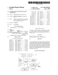
US007461790B2
(12) United States Patent
(10) Patent N0.2
McQueen et al.
(54)
US 7,461,790 B2
(45) Date of Patent:
Dec. 9, 2008
DATA READER AND METHODS FOR
IMAGING TARGETS EXPOSED TO HIGH
5,814,803 A
6,155,488 A
9/1998 Olmstead et al. .......... .. 235/462
12/2000 Olmstead et al. .......... .. 235/440
INTENSITY ILLUMINATION
6,311,895 B1
11/2001
75
_
( ) Inventors‘ $381562?‘hicQlll‘ielgtEgigéne’ 3R
’
an y
'
“r
a ’
'
ans“ e’
OH (Us)
(
*
~
.
6,520,415 B1*
2/2003
235/462.25
6,708,883 B2 *
3/2004 Krichever ......... .. 235/462.01
McMaster ............ .. 235/462.35
1/2006
2006/0163355 A1
7/2006 Olmstead et al. .......... .. 235/454
Barkan et al. ............. .. 235/454
OTHER PUBLICATIONS
)
Product Data Sheet: Sony 2048-pixel CCD Linear Sensor (B/W) for
~
( ) Nonce'
1/2003 Reddersen et al.
2006/0016893 A1*
(73) Assignee: Datalogic Scanning, Inc., Eugene, OR
US
Olmstead et al. ..... .. 235/46241
6,505,778 B1
~
~
-
Single 5V Power Supply Bar-code Reader ILX554B, downloaded
SubJeCt. to any dlsclalmer’. the term Ofthls
from: http://www.datasheetsite.com/datasheet/ILXS54, visited May
patent 15 extended or adjusted under 35
b b 0 da 5
USC‘ 154( ) y
y '
10 2007 13
’
’
PPS‘
User Manual: Avantes Avasort for AvaSpec-102/256/1024/2048 ver
sion 6.2 User’s Manual, pp. 27-29, (Aug. 2004) downloaded from:
(21) Appl- N05 11/6921664
http://www.avantes.com, visited May 10, 2007, 7 pps.
_
(22)
Takaya Yasuda et al., Variable-Integration-Time Image Sensor for
Flled:
Mar- 281 2007
(65)
Wide Dynamic Range, 2003, downloaded from: http://www.us.de
sign-reuse.com/articles/article7411.html, visited May 13, 2007, 11
pps.
Prior Publication Data
US 2007/0241192 A1
Oct. 18, 2007
* cited by examiner
Related US. Application Data
_ _
_
P1’imary ExamineriDaniel St-Cyr
_
(74) Attorney, Agent, or FirmiStoel Rives LLP
(60) Prov1s1onal appl1cat1on No. 60/744,261, ?led on Apr.
4, 2006-
(57)
(51)
A data reader such as for example an imaging reader with a
Int- Cl-
G06K 7/14
ABSTRACT
(2006-01)
CCD or CMOS imager or the like, that acquires an image of
(52)
US. Cl. ................................ .. 235/454; 235/462. 14
an item to be read' A Certain type of sensor has been found to
(58)
Field of Classi?cation Search ............... .. 235/454,
exhibit different outputs depending upon the light intensity
(56)
235/462.01, 462.14, 462.29, 462.32, 462.35,
235/ 462.45, 455, 462
See application ?le for complete search history.
References Cited
level: (1) standard output whereby the sensor outputs a signal
corresponding to the image collected and (2) inverted output
whereby the sensor outputs an inverted signal when the light
mtensrty h1gh1y saturates the sensor. Takmg advantage of th1s
inverted output, systems and methods are then employed by
the data reader to convert or otherwise re-invert this inverted
U.S. PATENT DOCUMENTS
signal in order to read an optical code that, for example, might
4,499,595 A
4,538,060
A
4,631,588 A
5,008,696 A *
5,770,847 A *
2/1985
Masaitis etal. .............. .. 382/9
8/1985
Sakai et al.
12/1986 Barnes et al.
4/1991
6/1998
.....
. . . ..
otherwise have been above the upper exposure limit of the
sensor/reader and thus not decodable.
235/472
358/149
Miida et al. ............... .. 396/104
14 Claims, 4 Drawing Sheets
Olmstead ............. .. 235/462.35
we
hml hum W
mm n
1
m
we"
US. Patent
Dec. 9, 2008
Sheet 1 of4
US 7,461,790 B2
Fig. 1
aw,
(Prior art)
Readout; ate
cmmwm
Mme gal-eater
@920
e .5.e mt n r
:1’\
\
SHEEN
Fig. 1'2‘
(Prior art)
US. Patent
Dec. 9, 2008
Sheet 2 of4
US 7,461,790 B2
LEVEL;
INVERTED
MODE
20
LOW LIGHT
LEVEL;
STANDARD
MODE
1O
15
Fig. 3
US. Patent
Dec. 9, 2008
Sheet 3 of4
US 7,461,790 B2
52
5O
US. Patent
Dec. 9, 2008
Sheet 4 of4
US 7,461,790 B2
Activate scanning; set inverted
mode to inactive;
start scanning time limit timer
Fig. 5
100
41—
> Scan and attempt decode
If good decode, acknowledge
and transmit
1 06
1 08
Deactivate
activated > scanning time limit ii>fYeS4>
\‘wrtias data been decode/d?”
.
/
scanning
1 10
\
inverted mode
.
active?
'Yes*
i
No
V
112
Check
exposure
116
4
ls exposure time 126
at
in
I
_
,
\ maximum limit?
/ “ ls sensor exposure ‘\
/§‘—C\
TOO dark
correct?
1 14
'
r)?
\\
Too bright
V
\‘
”
\
1
No
Yes
mode to active,
¢
N0
invert sensor
/ data destined for
1 2O
decoding
Calculate & set
Calculate and
set longer
shorter exposure
time based upon / 1 1 8
1 28
l
Set inverted
”
1
Yes
,r"
algorithms
desired sensor
exposure time /
Output VS
based upon
desired sensor
present output
1 24
i
p 15561512110
p
\
/ ls exposure time
exposure
Lemme“
by time 4*No
predetermined
increment
\‘mgxlmum
at'nv-enedim-iie
”
l \ 122
Yes
Set inverted mode to
123 /
v
V
V
V
inactive
1
US 7,461,790 B2
1
2
In a preferred con?guration, the data reader comprises an
DATA READER AND METHODS FOR
IMAGING TARGETS EXPOSED TO HIGH
INTENSITY ILLUMINATION
imaging reader, employing a sensor such as a CCD, that
acquires an image of an item to be read. A certain type of
sensor has been found to exhibit different outputs depending
upon the light intensity level: (1) standard output Whereby the
RELATED APPLICATION DATA
sensor outputs a signal corresponding to the image collected
and (2) inverted output Whereby the sensor outputs an
This application claims the bene?t under 35 U.S.C. § 119
(e) of US. Provisional Patent Application No. 60/744,261
inverted signal When the light intensity highly saturates the
sensor. Taking advantage of this inverted output, systems and
?led Apr. 4, 2006 hereby incorporated by reference.
methods are then employed by the data reader to convert or
otherWise re-invert this inverted signal in order to read an
BACKGROUND
optical code (for example) that otherWise Would have been
The ?eld of this disclosure relates to imaging and collec
tion devices and in particular to methods and devices for
above the upper exposure limit of the sensor/reader.
illumination, collection and imaging for optical code reading
the folloWing detailed description of preferred embodiments,
and other data and image capture devices.
Image capture and other data reading devices are used to
Which proceeds With reference to the accompanying draW
Additional aspects and advantages Will be apparent from
1ngs.
read optical codes, acquire data, and capture a variety of
images. One common data acquisition device is an optical
code reader. Optical codes typically comprise a pattern of
BRIEF DESCRIPTION OF THE DRAWINGS
20
dark elements and light spaces. There are various types of
FIG. 1 is a perspective vieW of a CCD sensor usable in a
optical codes, including 1-D codes (such as UPC and EAN/
system and method according to a preferred embodiment.
JAN barcodes) and 2-D codes (such as PDF-417 and Maxi
code). For convenience, some embodiments are described
herein With reference to capture of 1-D barcodes. HoWever,
FIG. 2 is a block diagram of the CCD sensor of FIG. 1.
the embodiments may also be useful for other optical codes
and symbols as Well as other images such as ?ngerprint cap
ture, and nothing herein should be construed as limiting this
disclosure to optical codes or particular types of codes.
One type of data reader is an imaging reader that employs
FIG. 3 is a graphical representation of detected signals
25
from a test barcode according to a preferred method.
FIG. 4 diagrammatic vieW of a data reader according to a
preferred embodiment.
FIG. 5 is a How chart of a method of data reading according
to a preferred embedment.
30
DETAILED DESCRIPTION OF PREFERRED
EMBODIMENTS
an imaging device or sensor array, such as a CCD (charge
coupled device) or CMOS (complementary metal oxide
semiconductor) device. Imaging readers can be con?gured to
read both 1-D and 2-D optical codes, as Well as other types of
optical codes or symbols and images of other items. When an
imaging reader is used to read an optical code, an image of the
optical code or portion thereof is focused onto a detector
Throughout the speci?cation, reference to “one embodi
35
that a particular described feature, structure, or characteristic
is included in at least one embodiment. Thus appearances of
the phrases “in one embodiment,” “in an embodiment,” or “in
array. Some imaging readers are capable of using ambient
some embodiments” in various places throughout this speci
light illumination, While other imaging readers employ a light
source to illuminate the item being scanned.
It is desirable for optical code scanners to have a Wide
dynamic range of usable illumination conditions over Which
40
?cation are not necessarily all referring to the same embodi
ment. Furthermore, the described features, structures, char
acteristics, and methods may be combined in any suitable
manner in one or more embodiments. In vieW of the disclo
they may operate. Typically, imaging optical code scanners
sure herein, those skilled in the art Will recogniZe that the
are required to Work in very loW light conditions (such as in a
dimly lit Warehouse With ambient light intensity on the order
ment,” or “an embodiment,” or “some embodiments” means
45
various embodiments can be practiced Without one or more of
full sunlight With light intensity over 100,000 lux). A lux is a
the speci?c details or With other methods, components, mate
rials, or the like. In other instances, Well-known structures,
unit of luminous incidence equal to one lumen per square
materials, or operations are not shoWn or not described in
of tens of lux) as Well as in high light conditions (such as in
meter. This large variation in ambient light conditions creates
a required dynamic range of 10,000>< or more. One possible
method of compensating for the large variation of ambient
light conditions is to equip the scanner With dynamic aper
tures or electronically adjustable attenuators. The present
detail to avoid obscuring aspects of the embodiments.
50
inventors have recogniZed that such compensation mecha
nisms add cost and complexity to the system and thus it Would
be desirable to provide a system that is entirely solid state,
With no moving parts. The design challenge is to create a
simple device With a broad dynamic range, Which usually
means electronically varying the integration time of the sen
55
sor as the primary means of exposure control.
60
utiliZing imaging technology. For conciseness of description,
the detector arrays are described as CCD arrays, but other
suitable detectors may be implemented such as CMOS.
The present inventors have found that certain sensors
Methods and devices are disclosed for improving reading
saturate the sensor array or portions thereof.
exhibit tWo output modes depending upon the light intensity
level namely a ?rst standard mode Whereby the sensor outputs
a signal corresponding to the image collected and a second
inverted mode Whereby the sensor outputs an inverted signal
When the light intensity highly saturates the sensor. One such
SUMMARY
of optical codes or other items being imaged, particularly
Where certain light conditions (eg bright sunlight) tend to
Preferred embodiments Will noW be described With refer
ence to the draWings. To facilitate description, any reference
numeral representing an element in one ?gure Will represent
the same element in any other ?gure.
Methods and devices according to the embodiments
described are particularly useful for presentation scanners
65
sensor is the Model ILX554B CCD linear sensor manufac
tured by Sony Corporation. The ILX554B model is a 2048
pixel CCD linear sensor, details of Which are available from
US 7,461,790 B2
4
3
the product data sheet hereby incorporated by reference.
In one embodiment, the scanner has tWo modes of opera
According to the product data sheet (at page 3), the ILX554B
tion, normal (or standard) and inverse (or inverted) video
sensor becomes saturated When exposure reaches about 0.004
lux~sec. This sensor outputs an inverted signal When exposure
reaches a highly saturated level on the order of several times
modes. When the scanner is ?rst triggered, it starts in normal
video mode and begins trying to set an exposure level that
places the video signal Within a desired optimum range. Dur
ing this normal mode, the video signal is treated in the signal
(or more) the saturation level.
processing chain as a non-inverted signal, and all calculations
FIG. 1 illustrates the CCD sensor 5 as a 22 pin DIP (dual
inline package), With a block diagram 7 of the circuit thereof
in the processing and decoding algorithms use this assump
illustrated in FIG. 2. The CCD sensor 5 includes a linear array
tion. If, after some ?xed time or number of captured frames of
data, a successful decode has not occurred and it is deter
of 2048 active pixels, shoWn in FIG. 2 as elements S1 through
S2048. The pixels of this sensor are rectangular having a
mined that the sensor (or sensors) is (are) in a high illumina
greater height (on the order of 5 6 pm) than Width (on the order
of 14 um) providing largerpixel area (i.e., greater sensitivity).
tion condition (i.e. highly saturated), the system changes to
inverted mode, and the data is deliberately re-inver‘ted by the
signal processing. The data may be re-inver‘ted by the A/D
FIG. 3 is a graphical representation of the output of the
converter or at any other suitable place in the signal process
ing/decoding chain. At the same time, the system starts to
adjust the exposure longer and longer in order to ensure that
the sensor is placed in the highly saturated state. With each
linear sensor 5 along a ?eld of vieW or scan line 15. The loWer
portion of FIG. 3 illustrates a test target 10 having a central
section comprised of light space 12 and dark bar 14 that for
test purposes corresponds to the bar and space of a barcode.
lengthening of the exposure, decoding is attempted. If indeed
The top portion of FIG. 3 illustrates tWo graphical represen
tations of the output of the sensor along scan line 15. Output
signal 20 illustrates a loW light level Where the target 15 is
illuminated via ambient light at a moderate light intensity
condition, such as on the order of 300 lux. At this ambient
20
inverted video at one of the exposure selections, then upon
re-inversion by the signal processing system, this data should
produce a successfully decoded label. If decoding is not suc
light intensity level, the output signal 20 readily distinguishes
betWeen an output level 22 corresponding to the bar 12 and an
cessful, the process of continually lengthening the exposure
25
output level 24 of the space 14. Thus this output signal may be
sent to a signal processor for decoding. Technically, the out
put of the model ILX554B CCD is such that the brighter/
higher light signal corresponding to the space 14 is a loWer
voltage and the darker/loWer light signal corresponding to the
there is su?icient illumination to cause the sensor to output
While inverting the data continues until a limit is reached,
such as an elapsed time or number of frames since being
triggered, or a maximum exposure. At this point, the scanner
may revert to normal video mode and the process starts from
the beginning as described above. This system and method
30
thus may provide a larger dynamic range.
bar 12 is a higher voltage. The curves of signals 20 and 30
FIG. 4 illustrates a handheld data reader 50 such as may be
shoWn in FIG. 3 have been inverted by the A/D (analog to
digital) converter of the system or elseWhere in the signal
equipped With the linear CCD described above. This reader
50 includes a head portion 52 connected to a handle portion
54. A WindoW 53 is disposed in the front section of the head
processing chain.
The CCD includes the capability of changing exposure.
35
operation, including light exposure. As the intensity of the
ambient light level increases, the system driving the CCD has
the capability of compensating for the increasing light by
adjusting exposure. If the sensor has an output level that
indicates the sensor is exposed to too much light, the control
system attempts to electronically reduce exposure time. HoW
ever in high light conditions such as in direct sunlight, the
sensor may reach its minimum exposure time and yet still be
saturated. When the sensor is saturated, the output signal is
such that the difference betWeen the respective signals corre
sponding to the bar 12 and space 14 of the optical code cannot
be readily distinguished. At a certain very high saturation
level, the output signal 30 of CCD is essentially inverted,
namely the output level 34 corresponds to the light space 14
40
45
The sensor’s output or the data representing the output is
then re-inver‘ted at some point in the signal processing/decod
ing chain and the resulting optical code data may then be
decoded. In one method, the system automatically determines
When the light ?ux is suf?ciently high to result in an inverted
signal, and When this condition occurs, the system inverts the
data during signal processing (Which may be described as
“re-inverted”) Which then produces a decodable signal. The
data may be re-inver‘ted by the A/ D converter or at any other
suitable place in the signal processing/ decoding chain
the reader is preferably equipped With illumination sources
that are activated during scanning or during other suitable
conditions.
FIG. 5 is a How chart illustrating a processing method 100
according to a preferred embodiment. The method includes
the steps of:
At Step 102, activating scanning, starting the scanning
limit timer, and setting inverted mode to inactive. Preferably,
at the start of scanning (e. g. on each trigger pull of the scan
ner) or after a successful scan, the mode is set to non-inverted,
50
the non-inverted mode being the more standard operating
mode.
At Step 104, scanning and attempting to decode.
At Step 105, if good decode is accomplished, acknoWledg
ing good read (typically by emitting an audible “beep” tone)
and the output level 32 corresponds to the dark bar 12. HoW
ever, unlike the loWer intensity saturation condition Where the
signals corresponding to the bar and space cannot be distin
guished, the high saturation level output signal 30 includes an
output level 34 (corresponding to the light space 14) that is
distinguishable from the output level 32 (corresponding to the
dark bar 12).
portion 52. This unit 50 is provided With a trigger 56 that is
manually actuable to initiate reading operation. Other suit
able reader con?gurations may be employed.
Though this reader may operate solely via ambient light,
The system includes a control system Which controls CCD
and transmitting the data.
55
60
At Step 106, determining (1) if scanning has been activated
for a time period greater than scanning time limit (eg if the
scanning limit timer has timed out) or (2) if the data has been
decoded, and if yes to either (1) or (2) proceed to Step 108 and
deactivate/stop scanning and if no, proceed to Step 110.
At Step 110, determining if inverted mode is activated, if
yes, proceed to Step 122, if no proceed to Step 112.
At Step 112, checking sensor exposure and at Step 114
determining if sensor exposure is correct. If exposure is cor
65
rect, return to Step 104. If exposure is too dark, proceed to
Step 126. If exposure is too bright, proceed to Step 116. One
method of determining Whether exposure is correct is to com
pare a measured value of the output signal level to a preferred
US 7,461,790 B2
5
6
or target range. If the signal level is above the target range, the
exposure is too bright. If the signal level is below the target
may be omitted as scanning time out at Step 106 Would be
reached and the system may attempt re-scan at Step 102.
range, the exposure is too dark.
Returning to Step 104 (in the inverted mode from Step 122
Where the exposure is too dark (meaning there is insu?i
or 124), since reading (decoding) Was unsuccessful in the
cient light illuminating the optical code), at Step 126 deter
standard, non-inverted mode, decoding is again attempted
mining Whether exposure time is at maximum limit. If yes,
With inverted data. If the CCD achieves the highly saturated
state and outputs inverted video, the decoding at Step 106
returning to Step 104, if no proceeding to Step 128.
At Step 128, setting a longer exposure time. The longer
(With inverted data from Step 120) may prove successful.
exposure time may be calculated based upon desired sensor
When operating in the inverted mode, the system then re
output relative to current signal level. Alternately, the expo
inverts the data during processing (for example at the A/D
sure time may be increased by a set increment or some other
converter or elseWhere in the signal processing chain) in order
to produce a decodable signal.
To further explain inverted mode processing, it may be
suitable methodology. Once the neW (longer) exposure time
is set, proceeding to Step 104 to attempt another scan.
If it is determined at Step 114 that the exposure is too light
useful to describe typical/ standard processing. In optical code
reader processing, there is typically a ?xed relationship
betWeen the voltage level of a signal representing the light and
(meaning there is too much light illuminating the optical
code), at Step 116 determining if exposure time is at mini
mum limit. If yes, proceeding to Step 120, if no proceeding to
Step 118.
At Step 118 setting a shorter exposure time. The shorter
exposure time may be calculated based upon desired sensor
20
output relative to current signal level. Alternately, the expo
sure time may be decreased by a set increment or some other
suitable methodology. Once the neW (shorter) exposure time
is set, proceeding to Step 104.
If at Step 116 it is determined that the exposure time is
already at the minimum time, the exposure level is too bright
and there is no further exposure reduction that can be made,
the method infers that processing may be successful in the
inverted mode. Thus proceeding to Step 120, inverted mode is
activated (inverted mode set to active) Whereby sensor data is
dark areas of a bar code, and the bar code’s actual light and
dark physical features. For example, at the sensor output, this
relationship may be that a more positive voltage represents a
brighter area, or, depending upon the sensor, a brighter area
may be represented by a loWer voltage level. In either case, a
typical system Will be designed to process the data based upon
the knoWn relationship betWeen the sensor’s output and the
bars and spaces of a barcode, so as to correctly process the
25
30
encoded data. The same Will be true through the digital pro
cessing chain of a typical reader. When the analog sensor
voltage is converted into a digital or logic level, there Will be
some ?xed relationship maintained betWeen the particular
logic level and the actual bar and space data. The decoding
algorithms in the reader make use of the ?xed, knoWn rela
inverted for processing by the decoding algorithms. The
tionship betWeen the incoming digital data and the original
methodmay proceed from Step 120 to Step 122 or alternately,
the method may skip Step 122 and proceed either directly to
bars and spaces of the encoded information.
Step 124 or to Step 104.
At Step 122, determining Whether exposure time (during
In a preferred system/method herein, the relationship
35
inverted mode) is at maximum limit. If yes proceeding to Step
123; if no proceeding to Step 124. The ?rst time through
(coming from Step 120), the exposure time is at the minimum
limit so the process Will determine at Step 122 that the pro
ceed to
normal, non-highly illuminated condition, the voltage levels
40
At Step 124, lengthening (or increasing) exposure time by
a given increment and returning to Step 104. The purpose of
Step 124 is to incrementally increase exposure and if the
exposure Was too bright at the minimum exposure setting (in
45
standard, non-inverted mode), the exposure setting is incre
mentally adjusted upWard toWard the maximum exposure
setting, thereby enhancing conditions for causing the sensor
to output inverted video (i. e., in the high saturation level). A
preferred increment of exposure lengthening may be on the
order of l mS. The increment may be larger or smaller. A
smaller increment, for example, on the order of 0.5 mS. This
preferred increment is fairly smallisuch a small increment is
preferred because it Would appear that the inverted-mode
operates most successfully in a fairly narroW exposure range.
Though an incremental increase of exposure is a preferred
method, other methods of adjusting the exposure may be
implemented such as increasing by a calculated amount based
on some factor. Alternately, the method may immediately
attempt maximum exposure and if not successful, attempt a
series of loWer exposures.
At Step 123, setting inverted mode to inactive and then
50
and their relationship to the bars and spaces of a barcode Will
have one state, for example, a high voltage level Will be
treated through the system as indicating a White space in the
bar code, and a loW voltage level Will indicate a black bar.
When the system determines that the sensor is in its highly
illuminated condition, the system’s state Will sWitch to the
inverted mode and the relationship betWeen the voltage levels
and the barcode features Will be inverted by the system. The
reversed relationship betWeen voltage and bar code features
Within the system in this inverted mode is used to compensate
for the inverted data issuing from the sensor.
There are several methods by Which the system may oper
ate in an inverted processing mode, including: (1) analog
hardWare such as a single transistor stage, Whereby the actual
voltage signal is inverted; (2) digital hardWare or logic signal
55
inverter; (3) a digital inverter circuit that outputs a voltage
representing the opposite logic-level as its input, the inverter
circuit serving as the basic logic gate to sWap betWeen those
tWo voltage levels; and (4) softWare. In the softWare method,
60
proceeding to Step 104. Upon reaching Step 123, the method
has cycled through the process having upped the exposure to
the maximum. Since decode has been unsuccessful in the
inverted mode, the inverted mode is set to inactive and the
method then scan attempts decode in standard mode. Step 123
betWeen the sensor data levels and the bars and spaces this
data is assumed to represent, may take one of tWo states,
depending upon Whether or not the sensor is in its highly
illuminated, inverted condition. When the sensor is in its
65
the signal may be inverted in softWare at any suitable stage
including at the pre-processing stage or at the decode stage.
In a preferred con?guration, the data reader may be pro
vided With multiple sensors. The sensors may be indepen
dently controlled or controlled by a common controller. In
one preferred method, once the method of controlling one of
the sensors is sWitched to inverted mode (pursuant to Step 120
above), the method of controlling the other sensor is also
sWitched to inverted mode.
US 7,461,790 B2
8
7
Wherein the system is operative to highly saturate the sen
In another control scheme, dual sensors are separately con
sor by increasing exposure time for enhancing probabil
trolled and portions combined. Certain methods for process
ity of the sensor to generate an inverted output signal.
4. A system according to claim 3 Wherein the exposure time
ing such a dual sensor system are disclosed in Olmstead et al.
U.S. Published Application No. US 2006-0163355 hereby
incorporated by reference.
is increased incrementally.
In yet another control scheme, either a second control
sensor, or a portion of the primary sensor, may be used to
provide informational feedback to the system for exposure
sensor Wherein the sensor is operative to generate an inverted
5. A method of operating an imaging system including a
output signal When the sensor is subjected to high intensity
illumination above a certain operating range, comprising the
steps of
if exposure on the sensor is too high, adjusting exposure by
control. The control sensor may be designed, such as With a
?lter or screen, that reduces the overall exposure thereby
allowing the control sensor to sense the exposure level at high
light levels, i.e., those light levels that normally Would create
shortening exposure time;
highly saturated or oversaturated levels in sensor 5. The sys
tem could then use the output from the control sensor to
determine Whether the output from the sensor 5 is inverted
such as by comparing the output of the control sensor to the
output of the sensor 5. If the output from the control sensor
if exposure on the sensor is still too high even after expo
sure time has been adjusted to a minimum, then (a)
increasing the exposure time and (b) processing the out
put signal from the sensor by reinverting the signal.
6. A method according to claim 5 Wherein the step of
increasing exposure comprises increasing the exposure time
indicates a high light level (e. g. a level that Would be expected
to be highly saturated to the sensor 5) and the output from the
sensor 5 otherWise appears to be in the normal range, then it
incrementally.
20
can be inferred With a reasonably high probability that the
sensor 5 output is inverted and thus signaling this alternate
system/method to sWitch to inverted mode.
Thus systems and methods for data reading and image
capture have been shoWn and described. It is nevertheless
intended that modi?cations to the disclosed systems and
methods may be made by those skilled in the art Without
25
exposure time;
ful decode, deactivating scanning.
9. A method according to claim 5 further comprising
The invention claimed is:
30
tion re?ecting from the item and to generate an output
signal corresponding thereto, Wherein the sensor is
operative to generate (a) a ?rst output sianal When the
35
ating range and (b) a second output signal that is inverted
subjected to high intensity illumination above the cer
invert the ?rst output signal from the sensor.
2. A system according to claim 1 Wherein the processor is
operative to process an output signal from the sensor (a) in a
standard mode When the sensor is subject to illumination
Within a standard operating range and (b) in an inverted mode
When the sensor is subjected to high intensity illumination
above a certain operating range and becomes highly saturated
and generates an inverted output signal.
3. A system for data reading of an item, comprising:
scanning;
40
45
sure time, and (b) upon reaching maximum exposure
time Without a successful decode, deactivating scan
ning.
50
When the sensor is subjected to high intensity illumina
tion above a certain operating range;
55
sensor is subjected to high intensity illumination above a
sensor is inverted by signal processing,
(2) incrementally increasing exposure time.
60
11. A method according to claim 10 Wherein the step of
incrementally increasing exposure time comprises incremen
sensor is subject to illuminatmon Within a standard oper
tain operating range and becomes highly saturated and
generates an inverted cutput signal,
upon determining that exposure time has been adjusted to
a minimum limit and exposure is still too high,
(1) sWitching to an inverted mode Wherein data from the
certain operating range and becomes highly saturated;
a processor for processing and decoding the output signal
ating range and (b) in an inverted mode When the sensor
is subjected to high intensity illumination above a cer
10. A method of image processing comprising the steps of
providing a sensor for an imaging system Wherein the
sensor is operative to generate an inverted output signal
tion re?ecting from the item and to generate an output
from the sensor, Wherein the processor is operative to
re-invert the inverted output signal from the sensor,
Where in the processor is operative to process an output
signal from the sensor (a) in a standard mode When the
if scanning has not exceeded scanning time limit, deter
mining if processing is in the inverted mode;
if processing is not in the inverted mode, proceeding to
standard mode exposure setting;
if processing is in the inverted mode: (a) increasing the
exposure time and attempting processing and decoding
in the inverted mode until reaching a maximum expo
a sensor arranged to receive a return signal from illumina
signal corresponding thereto, Wherein the sensor is
operative to generate an inverted output signal When the
if good decode accomplished, acknowledging good read
and transmitting data;
if good decode not accomplished, determining if scanning
has exceeded scanning time limit;
if scanning has exceeded scanning time limit, deactivating
relative to the ?rst output signal When the sensor is
tain operating range and becomes highly saturated;
a processor for processing and decoding the output signal
from the sensor, Wherein the processor is operative (a) to
invert the inverted second output signal and (b) to not
activating scanning;
upon activating scanning, setting processing mode to stan
dard mode;
scanning and attempting to decode;
a sensor arranged to receive a return signal from illumina
sensor is subjected to illumination beloW a certain oper
after each increment.
8. A method according to claim 5 further comprising:
increasing the exposure time until reaching a maximum
upon reaching maximum exposure time Without a success
departing from the underlying principles of set forth herein.
1. A system for data reading of an item, comprising:
7. A method according to claim 6 further comprising
increasing the exposure time by a lmS increment,
processing and attempting to decode in the inverted mode
65
tally increasing exposure by a given increment and re-scan
ning and attempting decode in the inverted mode.
12. A method according to claim 11 further comprising
repeating the steps of incrementally increasing exposure time
and re-scanning and attempting decode until a successful
decode or until scanning time limit has been reached.
US 7,461,790 B2
10
13. A method of image processing comprising the steps of
output signal When the sensor is subjected to illumination
intensity in a normal operating range and operative to gener
ate an inverted output signal that is inverted relative to the
standard output signal When the sensor is subjected to high
intensity illumination above a certain operating range, com
providing a sensor for an imaging system Wherein the
sensor is operative to generate (a) a ?rst output sicmal
When the sensor is subjected to illumination below a
certain operating range and (b) a second output signal
that is inverted relative to the ?rst signal When the sensor
is subjected to high intensity illumination above a cer
tain operating range;
compensating for the inverted second output signal from
the sensor by processing the inverted second output sig
nal in an inverted processing mode.
14. A method of operating an imaging system including a
sensor Wherein the sensor is operative to generate a standard
prising the steps of
processing the standard output signal from the sensor in a
standard processing mode;
10
processing the inverted output signal in an inverted pro
cessing mode.
UNITED STATES PATENT AND TRADEMARK OFFICE
CERTIFICATE OF CORRECTION
PATENT NO.
: 7,461,790 B2
Page 1 of 1
APPLICATION NO. : 11/692664
DATED
INVENTOR(S)
: December 9, 2008
: McQueen et a1.
It is certified that error appears in the above-identi?ed patent and that said Letters Patent is
hereby corrected as shown below:
Column 2
Line 26, before “diagrammatic” insert --is a--.
Column 5
Line 39, after “Step 122 that” insert --exposure time is not a maximum limit and thus--.
Line 40, after “proceed to” insert --Step 124.--.
Column 7
Line 34,
Line 61,
Line 63,
Line 67,
change “sianal” to --signal 2--.
change “wherein” to --Wherein--.
change “illurninatmon” to --illuminati0n--.
change “output” to --output--.
Column 8
Line 16, change “reinventing” to --re-inventing--.
Column 9
Line 3, change “sicmal” to --signal--.
Signed and Sealed this
Twenty-third Day of June, 2009
term
JOHN DOLL
Acting Director ofthe United States Patent and Trademark O?ice