1
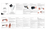
ACC5A
BATTERY OPERATED
COUNT TESTER
USER’S MANUAL
HP-253
August 1995
107 Kitty Hawk Lane, P.O. Box 2145, Elizabeth City, NC 27906-2145
800-628-4584 252-331-1997 FAX 252-331-2886
www.hofferflow.com E-mail: [email protected]
Notice
HOFFER FLOW CONTROLS, INC. MAKES NO WARRANTY OF ANY KIND
WITH REGARD TO THIS MATERIAL, INCLUDING, BUT NOT LIMITED TO,
THE IMPLIED WARRANTIES OF MERCHANTABILITY AND FITNESS FOR A
PARTICULAR PURPOSE.
This manual has been provided as an aid in installing, connecting, calibrating, operating, and
servicing this unit. Every precaution for accuracy has been taken in the preparation of this
manual; however, HOFFER FLOW CONTROLS, INC. neither assumes responsibility for any
omissions or errors that may appear nor assumes liability for any damages that may result from
the use of the products in accordance with information contained in the manual.
HOFFER FLOW CONTROLS' policy is to provide a user manual for each item supplied.
Therefore, all applicable user manuals should be examined before attempting to install or otherwise
connect a number of related subsystems.
During installation, care must be taken to select the correct interconnecting wiring drawing. The
choice of an incorrect connection drawing may result in damage to the system and/or one of the
components.
Please review the complete model number of each item to be connected and locate the appropriate
manual(s) and/or drawing(s). Identify all model numbers exactly before making any connections.
A number of options and accessories may be added to the main instrument, which are not shown
on the basic user wiring. Consult the appropriate option or accessory user manual before
connecting it to the system. In many cases, a system wiring drawing is available and may be
requested from HOFFER FLOW CONTROLS.
This document contains proprietary information, which is protected by copyright. All rights are
reserved. No part of this document may be photocopied, reproduced, or translated to another
language without the prior written consent of HOFFER FLOW CONTROLS, INC.
HOFFER FLOW CONTROLS’ policy is to make running changes, not model changes,
whenever an improvement is possible. This affords our customers the latest in technology and
engineering. The information contained in this document is subject to change without notice.
RETURN REQUESTS / INQUIRIES
Direct all warranty and repair requests/inquiries to the Hoffer Flow Controls Customer Service Department, telephone
number (252) 331-1997 or 1-800-628-4584. BEFORE RETURNING ANY PRODUCT(S) TO HOFFER FLOW
CONTROLS, PURCHASER MUST OBTAIN A RETURNED MATERIAL AUTHORIZATION (RMA) NUMBER FROM
HOFFER FLOW CONTROLS’ CUSTOMER SERVICE DEPARTMENT (IN ORDER TO AVOID PROCESSING
DELAYS). The assigned RMA number should then be marked on the outside of the return package and on any
correspondence.
FOR WARRANTY RETURNS, please have the
following information available BEFORE contacting
HOFFER FLOW CONTROLS:
1. P.O. number under which the product was
PURCHASED,
2. Model and serial number of the product under
warranty, and
3. Repair instructions and/or specific problems relative
to the product.
HFC 9708
FOR
REPAIRS
OR
NON-WARRANTY
consult
HOFFER
FLOW
CALIBRATIONS,
CONTROLS for current repair/calibration charges. Have
the following information available BEFORE contacting
HOFFER FLOW CONTROLS:
1. P.O. number to cover the COST of the
repair/calibration,
2. Model and serial number of the product, and
3. Repair instructions and/or specific problems relative
to the product.
LIMITED WARRANTY
HOFFER FLOW CONTROLS, INC. (“HFC”) warrants HFC’s products (“goods”) described in the specifications
incorporated in this manual to be free from defects in material and workmanship under normal use and service, but only
if such goods have been properly selected for the service intended, properly installed and properly operated and
maintained. This warranty shall extend for a period of (1) year from the date of delivery to the original purchaser (or
eighteen (18) months if the delivery to the original purchaser occurred outside the continental United States). This
warranty is extended only to the original purchaser (“Purchaser”). Purchaser’s sole and exclusive remedy is the repair
and/or replacement of nonconforming goods as provided in the following paragraphs.
In the event Purchaser believes the goods are defective, the goods must be returned to HFC, transportation prepaid by
Purchaser, within twelve (12) months after delivery of goods (or eighteen (18) months for goods delivered outside the
continental United States) for inspection by HFC. If HFC’s inspection determines that the workmanship or materials
are defective, the goods will be either repaired or replaced, at HFC’s sole determination, free of additional charge, and
the goods will be returned, transportation paid by HFC, using the lowest cost transportation available.
Prior to returning the goods to HFC, Purchaser must obtain a Returned Material Authorization (RMA) Number from
HFC’s Customer Service Department within 30 days after discovery of a purported breach of warranty, but no later than
the warranty period; otherwise, such claims shall be deemed waived. See the Return Requests/Inquiries Section of this
manual.
If HFC’s inspection reveals the goods are free of defects in material and workmanship or such inspection reveals the
goods were improperly used, improperly installed, and/or improperly selected for service intended, HFC will notify the
purchaser in writing and will deliver the goods back to purchaser upon (i) receipt of Purchaser’s written instructions
and (ii) the cost of transportation. If Purchaser does not respond within 30 days after notice from HFC, the goods will
be disposed of in HFC’s discretion.
HFC does not warrant these goods to meet the requirements of any safety code of any state, municipality, or any other
jurisdiction, and purchaser assumes all risk and liability whatsoever resulting from the use thereof, whether used singly
or in combination with other machines or apparatus.
This warranty shall not apply to any HFC goods or parts thereof, which have bee repaired outside HFC’s factory or
altered in any way, or have been subject to misuse, negligence, or accident, or have not been operated in accordance
with HFC’s printed instructions or have been operated under conditions more severe than, or otherwise exceeding, those
set forth in the specifications for such goods.
THIS WARRANTY IS EXPRESSLY IN LIEU OF ALL OTHER WARRANTIES, EXPRESSED OR IMPLIED,
INCLUDING ANY IMPLIED WARRANTLY OF MERCHANTABILITY OR FITNESS FOR A PARTICULAR
PURPOSE. HFC SHALL NOT BE LIABLE FOR ANY LOSS OR DAMAGE RESULTING, DIRECTLY OR INDIRECTLY,
FROM THE USE OF LOSS OF USE OF THE GOODS. WITHOUT LIMITING THE GENERALITY OF THE FOREGOING, THIS
EXCLUSION FROM LIABILITY EMBRACES THE PURCHASER’S EXPENSES FOR DOWNTIME, DAMAGES FOR WHICH
THE PURCHASER MAY BE LIABLE TO OTHER PERSONS, DAMAGES TO PROPERTY, AND INJURY TO OR DEATH OF
ANY PERSON. HFC NEITHER ASSUMES NOR AUTHORIZES ANY PERSON TO ASSUME FOR IT ANY OTHER
LIABILITY IN CONNECTION WITH THE SALE OR USE OF HFC’S GOODS, AND THERE ARE NO AGREEMENTS OR
WARRANTIES COLLATERAL TO OR AFFECTING THE AGREEMENT. PURCHASER’S SOLE AND EXCLUSIVE REMEDY
IS THE REPAIR AND/OR REPLACEMENT OF NONCONFORMING GOODS AS PROVIDED IN THE PRECEDING
PARAGRAPHS. HFC SHALL NOT BE LIABLE FOR ANY OTHER DAMAGES WHATSOEVER INCLUDING INDIRECT,
INCIDENTAL, OR CONSEQUENTIAL DAMAGES.
Disclaimer:
Specifications are subject to change without notice.
Some pages are left intentionally blank.
HFC 9708
MODEL ACC5A-101
GENERAL DESCRIPTION
The ACC5A is a test accessory used to verify operation of digital flow totalizers by generating a
signal which simulates the output of the turbine flowmeter.
Once started, the ACC5A generates a pulse train output signal which produces either 10,000 or
100,000 pulses depending on that desired by the operator. This may be used to verify the proper
operation of pulse scaling circuitry common to most digital flow totalizers.
In addition, the ACC5A has an amplitude select control which offers two output levels of 20 mVrms
and 200 mVrms to simulate the output level of a magnetic pickup at low flow and high flow
conditions.
To further increase the usefulness of this accessory, the frequency of the output signal may be varied
to simulate the varying flowrate conditions which occur in real applications. A single turn dial is used
to select a frequency of 100 to 1000 Hz.
The ACC5A is offered in a portable, hand-held case and contains an internal power source eliminating
the need for conventional power. The output connector is the standard two pin configuration
standard to nearly all turbine flowmeter magnetic pickups.
CONTROLS AND ADJUSTMENTS
POWER
A conventional power switch is provided for turning on ACC5A.
FREQUENCY
A single turn dial which allows the operator to select a frequency from
100 to 1000 Hz. Used to simulate rate of flow.
COUNT
A switch control which is used to select a burst of either 10,000 or
100,000 pulses. Used to verify proper operation of pulse scaling
circuitry.
AMPLITUDE
A switch control which is used to select the amplitude of the output
signal, used to simulate the amplitude at low flow and high flow
conditions.
START
A momentary switch which is used to start the ACC5A by enabling a
burst of the desired number of pulses.
RESET
A momentary switch which is used to manually stop and reset the
output of the ACC5A. This allows the operator to cut short a test
which apparently not producing the desired results in a unit under test.
HFC 9508 REV. (2.00)
-1-
HP-253
SPECIFICATIONS
OUTPUT
Square Wave output waveform. Amplitude, frequency and number of
pulses in output burst adjustable by user.
AMPLITUDE
20 mVrms and 200 mVrms available through switch selection.
FREQUENCY
100 to 1000 Hz (standard), adjustable through frequency control.
PRESET OUTPUT
BURST
Either 10,000 not 100,000 pulses may be selected.
POWER
9 Vdc transistor battery.
EQUIPMENT
ENCLOSURE
5¼ x 2¾ x 1e ABS Plastic with aluminum panel.
CONNECTOR
(OUTPUT)
MS3102A-10SL-4P.
HFC 9508 REV. (2.00)
-2-
HP-253
BASIC TEST SETUP WHEN USING THE ACC5A
The following guide presents an overview of several possible applications where the ACC5A may be
used to test turbine flowmeter based systems.
The basic setup for using the ACC5A requires that the flowmeter pickup coil signal be disconnected
at the flowmeter and connected instead to the ACC5A output connector. The output connector
corresponds to the industry standard for magnetic pickups in its physical configuration.
Once connected to the system to be tested, turn the power on the both the ACC5A and the unit to
be tested. The ACC5A should then be reset by depressing the start and then the stop switch. Testing
may then begin.
The procedure to be used will generally follow the guidelines given in the following examples. For
detailed procedures for a specific model consult with the equipment manual for that item.
The Output Signal from the ACC5A may be setup to be one of two amplitudes, at any frequency
between 100 and 1000 Hz and for a specified number of output pulses. The output signal is started
by depressing the START switch, once started it will produce a burst of pulses until either stopped
or when the PRESET number of pulses is delivered.
The ACC5A, once started produces a series of output pulses the number of which is determined by
the PRESET setting. Two settings are available, being 10,000 and 100,000 pulses. After the desired
number of pulses are produced the ACC5A turns off the pulse output signal. The time it takes to
produce this number is a function of the FREQUENCY setting.
The frequency is variable from 100 to 1000 Hz depending on the setting of the FREQUENCY dial.
The amplitude of the output signal may be set to either 20 mV or 200 mVrms with the AMPLITUDE
control.
The ACC5A is intended to function as a low cost troubleshooting aid to test turbine flowmeter based
electronic systems. The POWER switch should be turned off when the ACC5A is not in use.
HFC 9508 REV. (2.00)
-3-
HP-253
TESTING THE PULSE SCALING CIRCUITRY OF A DIGITAL TOTALIZER
Digital flow totalizers scale the pulsing input signal from a turbine flowmeter into a pulse counter
display by effectively dividing by the number of pulses per unit volume the flowmeter produces.
Referred to as the K-Factor, this number is given by the manufacturer of the turbine flowmeter and
is used in the setup of all flow totalizers.
There are two means commonly employed to scale the flowmeter signal into the display of total flow
in the desired units of measure. The first simply divides the number of input pulses by the
programmed scaling constant. The second method multiplies the input pulse train by the scaling
constant setting. For this later case this is a factor less than unity.
Regardless of the method of scaling used, the ACC5A may be used to verify that the scaling is being
performed correctly. Once the ACC5A is started is produces a burst of either 10,000 or 100,000
pulses depending on PRESET setting. The lower setting may be used to increase the resolution of
he resulting display.
A flow totalizer should therefore scale these pulses by the scaling factor and display that result when
the ACC5A automatically turns off. The display which should result may be calculated with the aid
of the following equations. Choose the equation type corresponding to the method of scaling used
in the instrument. Note that in some systems there may be a cascade of a scaling factor and scaling
factor multiplier. In most cases these two factors may be checked out independently as well as in
cascade.
If unit scales the input signal by dividing by the scaling factor setting, use the following expression:
Total Display = Preset setting of ACC5A / Scaling Factor
If the unit scales the input signal by multiplying by the scaling factor setting, use the following
expression:
Total Display = Preset Setting of ACC5A X Scaling Factor
When testing, first reset the total display, then start the ACC5A. When the totalizer stops counting
the result should equal that calculated by the above equations.
HFC 9508 REV. (2.00)
-4-
HP-253
USING THE ACC5A TO SETUP AND TEST FLOWRATE INDICATORS
Flowrate indicators scale the frequency signal of the turbine flowmeter which is linearly related to
flowrate into a display of flowrate in the desired units of measure.
The ACC5A can generate a frequency from 100 to 1000 Hz during its output burst. The ACC5A
may be used in conjunction with a frequency counter to test flow rate indicators.
To test a flowrate indicator set the output frequency of the ACC5A to a frequency corresponding to
a know flowrate using a frequency counter for the measurement. The flowrate indicator reading
should equal that flowrate expected. If not, recalibrate the flowrate indicator.
The linearity of the flowrate indicator may be tested by inputting several frequencies and verifying
that the readings change proportionally.
USING THE ACC5A TO TEST SIGNAL CONVERTERS
Signal converters for turbine flowmeter convert the frequency of the turbine flowmeter into an analog
voltage or current signal which is proportional to flowrate.
The same basic test setup used for testing flowrate indicators may be used for testing signal
converters except that the analog output has to be monitored by a digital multimeter.
Once again the input signal conditioning, analog span, zero, and linearity may be tested using the
ACC5A, multimeter and a frequency counter.
HFC 9508 REV. (2.00)
-5-
HP-253
A COMPARISON BETWEEN THE ACC5 AND THE ACC5A
The ACC5 was an earlier version of a test accessory which has found widespread application in
industry. A number of procedures have therefore been written around it.
To use the ACC5A in these applications place the PRESET in the 10K position, the amplitude in the
200mV position and he frequency in the minimum position. The ACC5A will then act like the ACC5.
As you become comfortable with its use try running your tests a the maximum frequency. You can
see what a time saver this new unit is.
If you get a malfunctioning unit which works on the ACC5A but not on the flowmeter it may be that
the signal conditioner card is not sensitive enough, you can verify this by testing at a 20 mV amplitude
setting.
Did you ever want to see more resolution on the result of a test of the scaling factor? Try a test at
maximum frequency with a preset of 100K. You will see a result with ten times the resolution in the
same time as your old tests. You also can see how the display works at higher speeds.
When your done don’t forget to turn off the power switch. The battery inside is a 9 V transistor
radio battery, this is something to think about changing if the ACC5A isn’t working right.
Remember the ACC5A has battery, this means you will not have to run extension cords when testing
anymore.
The ACC5 was more rugged than this new unit and bigger. Keep the ACC5A in a safe place.
Call with any questions that you might have. If someone from Hoffer is in your area ask him to
demonstrate the new ACC5A for you and show you ways to help you meter checkouts faster and
better.
HFC 9508 REV. (2.00)
-6-
HP-253