1
PISO-CM100-D/T
User’s Manual
Warranty
All products manufactured by ICP DAS are warranted
against defective materials for a period of one year from
the date of delivery to the original purchaser.
Warning
ICP DAS assume no liability for damages consequent
to the use of this product. ICP DAS reserves the right to
change this manual at any time without notice. The
information furnished by ICP DAS is believed to be
accurate and reliable. However, no responsibility is
assumed by ICP DAS for its use, nor for any infringements
of patents or other rights of third parties resulting from its
use.
Copyright
Copyright 2007 by ICP DAS. All rights are reserved.
Trademark
The names used for identification only maybe
registered trademarks of their respective companies.
PISO-CM100 User’s Manual
(Version: 1.02
February 5, 2008)
1
Tables of Content
1
2
3
4
General Information................................................................................6
1.1 Introduction....................................................................................6
1.2 Features..........................................................................................7
1.3 Specifications ................................................................................8
1.4 Product Check List ........................................................................9
Hardware Configuration .......................................................................10
2.1 Board Layout................................................................................10
2.2 Jumper Selection......................................................................... 11
2.3 Connector Pin Assignment .........................................................12
2.3.1
5-pin screw terminal connector .....................................12
2.3.2
9-pin D-sub male connectors .........................................13
2.3.3
Wire connection ..............................................................14
2.4 LED Indicator & PISO-CM100-D/T Mode ....................................15
2.5 Hardware Installation...................................................................16
Driver Introduction ...............................................................................17
3.1 Software Installation....................................................................17
3.2 Software Architecture..................................................................22
APIs for Windows Application .............................................................25
4.1 Windows API Definitions and Descriptions...............................25
4.1.1
CM100_GetDllVersion .....................................................29
4.1.2
CM100_GetBoardInf ........................................................30
4.1.3
CM100_TotalBoard ..........................................................31
4.1.4
CM100_TotalCM100Board ..............................................31
4.1.5
CM100_TotalDNM100Board............................................32
4.1.6
CM100_TotalCPM100Board ............................................32
4.1.7
CM100_GetCM100BoardSwitchNo.................................33
4.1.8
CM100_GetDNM100BoardSwitchNo ..............................34
4.1.9
CM100_GetCPM100BoardSwitchNo ..............................35
4.1.10 CM100_GetCardPortNum ...............................................36
4.1.11 CM100_ActiveBoard........................................................37
4.1.12 CM100_CloseBoard.........................................................38
4.1.13 CM100_BoardIsActive.....................................................39
4.1.14 CM100_ AdujstDateTime.................................................40
4.1.15 CM100_Reset ...................................................................41
4.1.16 CM100_Init .......................................................................42
4.1.17 CM100_HardwareReset...................................................43
PISO-CM100 User’s Manual
(Version: 1.02
February 5, 2008)
2
4.1.18
4.1.19
4.1.20
4.1.21
4.1.22
4.1.23
4.1.24
4.1.25
4.1.26
4.1.27
4.1.28
4.1.29
CM100_Check186Mode...................................................44
CM100_Status..................................................................45
CM100_AddCyclicTxMsg ................................................47
CM100_DeleteCyclicTxMsg ............................................49
CM100_EnableCyclicTxMsg ...........................................50
CM100_DisableCyclicTxMsg ..........................................51
CM100_OutputByte .........................................................52
CM100_InputByte ............................................................53
CM100_ClearSoftBuffer <For default firmware> ...................54
CM100_ClearBufferStatus <For default firmware>................55
CM100_ClearDataOverrun <For default firmware> ...............56
CM100_Config <For default firmware>...................................57
4.1.30
4.1.31
4.1.32
CM100_ConfigWithoutStruct <For default firmware> ...........60
CM100_RxMsgCount <For default firmware> ........................61
CM100_ReceiveMsg <For default firmware> .........................62
4.1.33
4.1.34
4.1.35
4.1.36
4.1.37
4.1.38
4.1.39
4.1.40
4.1.41
4.1.42
4.1.43
CM100_ReceiveWithoutStruct <For default firmware> .........64
CM100_SendMsg <For default firmware> ..............................66
CM100_SendWithoutStruct <For default firmware> ..............67
CM100_SJA1000Config <For user-defined firmware> ............69
CM100_DPRAMInttToCM100 <For user-defined firmware> ....70
CM100_DPRAMWriteByte <For user-defined firmware> .........71
CM100_DPRAMWriteWord <For user-defined firmware> .......72
CM100_DPRAMWriteDword <For user-defined firmware> .....73
CM100_DPRAMWriteMultiByte <For user-defined firmware> 74
CM100_DPRAMReadByte <For user-defined firmware> .........75
CM100_DPRAMReadWord <For user-defined firmware> .......76
CM100_DPRAMReadDword <For user-defined firmware> .....77
CM100_DPRAMReadMultiByte <For user-defined firmware> 78
CM100_DPRAMMemset <For user-defined firmware> ............79
CM100_ReceiveCmd <For user-defined firmware> .................80
CM100_SendCmd <For user-defined firmware> ......................81
CM100_InstallUserISR <For user-defined firmware> ..............82
4.1.44
4.1.45
4.1.46
4.1.47
4.1.48
4.1.49
5
4.1.50 CM100_RemoveUserISR <For user-defined firmware>...........83
4.2 Windows API Return Codes Troubleshooting...........................84
Functions of Firmware Library ............................................................86
5.1 Firmware Library Definitions and Descriptions ........................86
5.1.1
L1Off .................................................................................90
5.1.2
L1On .................................................................................90
PISO-CM100 User’s Manual
(Version: 1.02
February 5, 2008)
3
5.1.3
5.1.4
5.1.5
5.1.6
5.1.7
5.1.8
5.1.9
5.1.10
5.1.11
5.1.12
5.1.13
5.1.14
5.1.15
5.1.16
5.1.17
5.1.18
L2Off .................................................................................91
L2On .................................................................................91
DPRAMInttToHost ...........................................................92
UserDPRAMIrqFunc <must be called once > ........................93
DPRAMWriteByte ............................................................94
DPRAMWriteWord ...........................................................95
DPRAMWriteDword .........................................................96
DPRAMWriteMultiByte ....................................................97
DPRAMReadByte.............................................................98
DPRAMReadWord ...........................................................99
DPRAMReadDword .......................................................100
DPRAMReadMultiByte ..................................................101
DPRAMMemset..............................................................102
DPRAMReceiveCmd......................................................103
DPRAMSendCmd ..........................................................104
DebugPrint <assist with CM100_DEBUG_MONITOR.EXE> ......105
5.1.19
5.1.20
5.1.21
5.1.22
5.1.23
5.1.24
5.1.25
5.1.26
5.1.27
5.1.28
5.1.29
5.1.30
5.1.31
5.1.32
5.1.33
5.1.34
5.1.35
5.1.36
5.1.37
5.1.38
5.1.39
5.1.40
GetKbhit <assist with debug cable and 7188xw.exe>................106
Print <assist with debug cable and 7188xw.exe> .......................107
GetTime ..........................................................................108
SetTime ..........................................................................109
GetDate .......................................................................... 110
SetDate........................................................................... 111
GetWeekDay .................................................................. 112
ReadNVRAM .................................................................. 113
WriteNVRAM .................................................................. 114
GetTimeTicks100us....................................................... 115
GetTimeTicks................................................................. 116
DelayMs.......................................................................... 117
CM100_InstallUserTimer............................................... 118
T_StopWatchXXX series functions .............................. 119
T_CountDownTimerXXX series functions...................121
CM100_EEPROMReadByte...........................................123
CM100_EEPROMReadMultiByte ..................................124
CM100_EEPROMWriteByte...........................................125
CM100_EEPROMWriteMultiByte ..................................126
UserCANIrqFunc <must be called once> ............................127
SJA1000HardwareReset ...............................................128
SetCANBaud ..................................................................129
PISO-CM100 User’s Manual
(Version: 1.02
February 5, 2008)
4
5.1.41
5.1.42
5.1.43
5.1.44
5.1.45
5.1.46
5.1.47
5.1.48
5.1.49
5.1.50
5.1.51
5.1.52
5.1.53
5.1.54
5.1.55
5.1.56
5.1.57
5.1.58
5.1.59
5.1.60
5.1.61
5.1.62
5.1.63
6
GetCANBaud..................................................................130
SetCANMask ..................................................................131
GetCANMask..................................................................133
CANConfig .....................................................................134
EnableSJA1000..............................................................135
DisableSJA1000.............................................................135
GetCANStatus................................................................136
ClearDataOverrunStatus...............................................137
SendCANMsg.................................................................138
ClearTxSoftBuffer..........................................................139
GetCANMsg ...................................................................140
ClearRxSoftBuffer .........................................................142
RxMsgCount ..................................................................142
AddCyclicTxMsg ...........................................................143
DeleteCyclicTxMsg........................................................144
EnableCyclicTxMsg.......................................................145
DisableCyclicTxMsg......................................................146
ResetCyclicTxBuf..........................................................146
SystemHardwareReset .................................................147
SystemInit ......................................................................147
GetLibVer .......................................................................148
RefreshWDT...................................................................148
UserInitFunc <must be called once>....................................149
5.1.64 UserLoopFunc <must be called once> ................................150
5.2 Firmware Library Return Codes Troubleshooting ..................151
Application Programming ..................................................................153
6.1 Windows Programming With Default Firmware ......................153
6.2 Introduction of CANUtility Tool ................................................161
6.3 Debug Tools for User-defined Firmware Programming..........173
6.4 User-defined Firmware Programming......................................178
PISO-CM100 User’s Manual
(Version: 1.02
February 5, 2008)
5
1
General Information
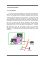
1.1 Introduction
The CAN (Controller Area Network) is a serial communication protocol,
which efficiently supports distributed real-time control with a very high level of
security. It is especially suited for networking "intelligent" devices as well as
sensors and actuators within a system or sub-system. In CAN networks, there
is no addressing of subscribers or stations in the conventional sense, but
instead prioritized messages are transmitted. As a stand-alone CAN controller,
PISO-CM100 represents a powerful and economic solution. The PISO-CM100
with a 186 CPU inside has one CAN bus communication port with either a
5-pin screw terminal connector or a 9-pin D-sub connector. It can be used as
master/slave function to cover a wide range of CAN applications. In addition,
the PISO-CM100 uses the new Phillips SJA1000T and transceiver
82C250/251, which provide the bus arbitration and error detection. It can be
installed in a 5V 32-bit PCI slot and is supported with actual “Plug & Play”
technology.
PISO-CM100 User’s Manual
(Version: 1.02
February 5, 2008)
6
1.2 Features
z
33MHz 32bit 5V PCI bus (V2.1) plug and play technology
z
Follow ISO11898-2 specification
z
Philip SJA1000T CAN controller
z
Philip 82C250 CAN transceiver
z
CAN controller frequency :16 MHz
z
2500Vrms photo-isolation protection on CAN side
z
Jumper select 120Ω terminator resistor for CAN bus
z
One CAN communication port
z
Compatible with CAN specification 2.0 parts A and B
z
Provide default baud 10Kbps, 20Kbps, 50Kbps, 125Kbps, 250Kbps,
500Kbps, 800Kbps, and 1Mbps
z
Allow user-defined baud
z
2048 records reception buffer and 256 records transmission buffer
z
Cyclic transmission precision: ±0.5ms precision when cyclic time is
below 10ms , ±1% error when cyclic time exceeds 10ms.
z
Provide 5 sets of cyclic transmission.
z
Timestamp of CAN message with at least ±1ms precision
z
186 compactable CPU inside
z
8K bytes DPRAM inside
z
RTC(Real Time Clock) inside
z
2 indication LED (one for green and another for red)
z
Support user-defined firmware
z
Support firmware update
z
VC++, VB, BCB demos and libraries are given
z
C/C++ function libraries of firmware side is given
z
Driver supported for Windows 98/Me/NT/2000/XP
PISO-CM100 User’s Manual
(Version: 1.02
February 5, 2008)
7
1.3 Specifications
z
CAN controller: Phillips SJA1000T
z
CAN controller frequency :16 MHz
z
CAN transceiver: Phillips 82C250.
z
Follow ISO11898-2 specification
z
One CAN communication port
z
Compatible with CAN specification 2.0 parts A and B
z
Jumper select 120Ω terminator resistor for CAN bus
z
Provide default baud 10Kbps, 20Kbps, 50Kbps, 125Kbps, 250Kbps,
500Kbps, 800Kbps, and 1Mbps
z
Allow user-defined baud
z
Connector: 5-pin screw terminal connector or 9-pin D-sub male
connector.
z
Isolation voltage: 2500Vrms on CAN side
z
33MHz 32bit 5V PCI bus (V2.1) plug and play technology
z
186 compactable CPU
z
8K bytes DPRAM (1K bytes for system)
z
512 K bytes Flash memory (128K bytes for system, others for
firmware)
z
512K bytes SRAM
z
RTC (real time clock) inside
z
2K EEPROM (256 bytes for system)
z
31 bytes NVRAM
z
Power requirements:
5V@400mA
z
Environment:
Operating temp: 0~60℃
Storage temp: -20~80℃
Humidity: 0~90% non-condensing
Dimensions: 127mm X 121mm
PISO-CM100 User’s Manual
(Version: 1.02
February 5, 2008)
8
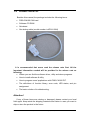
1.4 Product Check List
Besides this manual, the package includes the following items:
PISO-CM100 CAN card
Software CD ROM
Quickstart
One debug cable (model number is 4PCA-0904)
It is recommended that users read the release note first. All the
important information needed will be provided in the release note as
following:
Where you can find the software driver, utility and demo programs.
How to install software & utility.
How to program users’ applications with PISO-CM100 D/T.
The definitions of function library, error code, LED status, and pin
assignment.
The basic solution of troubleshooting.
Attention !
If any of these items are missing or damaged, please contact your local
field agent. Keep aside the shipping materials and carton in case you want to
ship or store the product in the future.
PISO-CM100 User’s Manual
(Version: 1.02
February 5, 2008)
9
2
Hardware Configuration
This section will describe the hardware settings of the PISO-CM100. This
information includes the wire connection and terminal resistance configuration
for the CAN network.
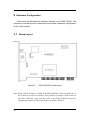
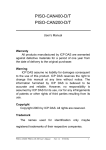
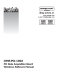
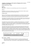
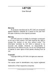
2.1 Board Layout
Figure2.1
PISO-CM100-D board layout
Note: PISO-CM100-T layout is similar with PISO-CM100-D. The only difference is
the position of CAN port connector. The positions of jumper or DIP switch are
the same. Therefore, users can also refer to the PISO-CM100-D layout to
configure the jumper or DIP switch if they use PISO-CM100-T.
PISO-CM100 User’s Manual
10
(Version: 1.02
February 5, 2008)
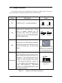
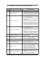
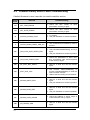
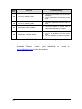
2.2 Jumper Selection
The following table shows the definition of jumpers or DIP switch. Users need to
refer to this table to configure the PISO-CM100- D/T hardware.
Jumper
Description
Status
JP1
JP1
JP1
CAN Port 120Ω terminal resistance.
Enable
Disable
Enable
Disable
Reset pin for download error. If users
want to update firmware but the
JP3
JP4
DIP switch
process is fail, users can enable this
jumper to reset the PISO-CM100-D/T
into download mode.
Debug port for user-defined firmware.
Users can connect the debug port with
the PC RS-232 port via the debug
cable.
4-pin connector for JP4
D-Sub 9 pin connector
for PC RS-232 port
DIP switch is used to set the
PISO-CM100 board No. Switch1 is for
bit0, switch2 is for bit1 and so forth. For
example, if the left-hand-side switch
(switch 1) is ON, the board No. is set to
1. The range of board No. is from 0 to
This situation indicates the
15. Be careful that the board No. for
board No. 1.
each PISO-CM100-D/T, PISO-DNM
100-D/T and PISO-CPM100-D/T must
be unique in the PC.
Table 2.1
PISO-CM100 User’s Manual
Jumper or DIP switch selections
(Version: 1.02
February 5, 2008)
11
2.3 Connector Pin Assignment
The PISO-CM100-T is equipped with one 5-pin screw terminal
connector and the PISO-CM100-D is equipped with one 9-pin D-sub male
connector for wire connection of the CAN bus. The connector’s pin
assignment is specified as following:
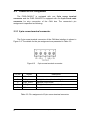
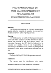
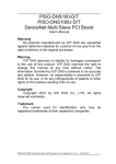
2.3.1 5-pin screw terminal connector
The 5-pin screw terminal connector of the CAN bus interface is shown in
Figure 2.2. The details for the pin assignment are presented in Table 2.2.
Figure2.2
Pin No.
5-pin screw terminal connector
Signal
Description
1
N/A
No use
2
CAN_H
CAN_H bus line (dominant high)
3
CAN_SHLD
Optional CAN Shield
4
CAN_L
CAN_L bus line (dominant low)
5
N/A
No use
Table 2.2: Pin assignment of 5-pin screw terminal connector
PISO-CM100 User’s Manual
12
(Version: 1.02
February 5, 2008)
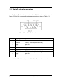
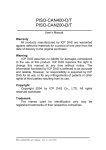
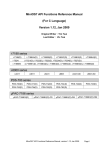
2.3.2 9-pin D-sub male connectors
The 9-pin D-sub male connector of the CAN bus interface is shown in
Figure 2.3 and the corresponding pin assignments are given in Table 2.3.
Figure2.3
Pin No.
9-pin D-sub male connector
Signal
Description
1
N/A
No use
2
CAN_L
CAN_L bus line (dominant low)
3
N/A
No use
4
N/A
No use
5
CAN_SHLD
Optional CAN Shield
6
N/A
No use
7
CAN_H
CAN_H bus line (dominant high)
8
N/A
No use
9
N/A
No use
Table 2.3
Pin assignment of the 9-pin D-sub male connector
PISO-CM100 User’s Manual
13
(Version: 1.02
February 5, 2008)
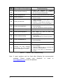
2.3.3 Wire connection
In order to minimize the reflection effects on the CAN bus line, the CAN
bus line has to be terminated at both ends by two terminal resistances as in the
following figure. According to the ISO 11898-2 spec, each terminal resistance
is 120Ω (or between 108Ω~132Ω). The length related resistance should have
70 mΩ/m. Users should check the resistances of the CAN bus, before they
install a new CAN network.
Device 1
Device 2
...
Device N
120Ω
120Ω
CAN_H
CAN_L
Figure 2.4
CAN bus network topology
Moreover, to minimize the voltage drop over long distances, the terminal
resistance should be higher than the value defined in the ISO 11898-2. The
following table can be used as a good reference.
Bus Cable Parameters
Terminal
Resistance
(Ω)
Bus Length
(meter)
Length Related
Resistance
(mΩ/m)
0~40
70
0.25(23AWG)~
0.34mm2(22AWG)
124 (0.1%)
40~300
< 60
0.34(22AWG)~
0.6mm2(20AWG)
127 (0.1%)
300~600
< 40
0.5~0.6mm2
(20AWG)
150~300
600~1K
< 20
0.75~0.8mm2
(18AWG)
150~300
Table 2.4
Cross Section
(Type)
Relationship between cable characteristics and terminal resistance
PISO-CM100 User’s Manual
14
(Version: 1.02
February 5, 2008)
2.4 LED Indicator & PISO-CM100-D/T Mode
The LED status will be changed when PISO-CM100-D/T is in different
mode. There are three modes, and each mode describes as following:
1.
Download mode: In this case, Green LED and red LED will flash once per
second. (When green LED is ON, red LED is OFF. When
red LED is ON, green LED is OFF). At the same time,
PISO-CM100-D/T will prepare to update the firmware
from Utility. Therefore, users can use Utility to download
the newer default firmware or the user-defined firmware.
2.
Firmware mode: If PISO-CM100-D/T uses default firmware, the green
LED will be flashed once when PISO-CM100-D/T
receive or transmit one CAN message to CAN bus
successfully. If bus loading is heavy, the green LED will
turn on always. When some error occurs, the red LED
will turn on. Users can use CM100_Status() function to
get the situation except buffer status. Reading or
sending CAN messages can get the buffer status from
the return code of functions. If PISO-CM100-D/T uses
user-defined firmware, users can design the green LED
or red LED status by themselves.
3.
Firmware reset mode: If users enable JP3 described in section 2.2, both
red and green LED will turn on about 1 second. At
the same time, PISO-CM100-D/T is forced to enter
download mode. When PISO-CM100-D/T is out of
control because of user-defined firmware or some
problems, use this method to reset firmware and
download newer firmware again.
PISO-CM100 User’s Manual
15
(Version: 1.02
February 5, 2008)
2.5 Hardware Installation
When users want to use PISO-CM100-D/T, the hardware installation
needs to be finished as following steps.
1. Shutdown your personal computer.
2. Configure the DIP switch and JP1 of the PISO-CM100-D/T for the board No.
and the terminal resistance. The more detail information could be found on
the figure 2.1 and table 2.1.
3. Check JP3 and JP4 status of PISO-CM100-D/T. If necessary, enable them.
4. Find an empty PCI slot for the PISO-CM100-D/T on the mother board of the
personal computer. Plug the configured PISO-CM100-D/T into this empty
PCI slot.
5. Plug the CAN bus cable(s) into the 5-pin screw terminal connector or the
9-pin D-sub connector.
When the procedure described above is completed, turn on the PC.
PISO-CM100 User’s Manual
16
(Version: 1.02
February 5, 2008)
3
Driver Introduction
3.1 Software Installation
The PISO-CM100-D/T can be used in Windows 98/Me/NT/2000/XP
environments. Users need to get proper driver for their operation system.
These drivers are in Field Bus CD in the PISO-CM100-D/T package. The path
is CAN\PCI\PISO-CM100. Also, users can find them from our website as
following.
http://www.icpdas.com/download/can/PCI_Interface.htm
The recommended installation procedure is given as below:
Step 1: Shut down your PC.
Step 2: Plug your PISO-CM100-D/T into an available PCI slot.
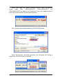
Step 3:
Boot up your PC. When system detects a new card and pop up a
wizard dialog for driver installation, cancel this dialog and skip the
procedure of driver installation.
Step 4:
Get the proper PISO-CM100-D/T driver for your operation system.
These drivers can be found in CD of PISO-CM100-D/T package or
our website.
Step 5:
Install the driver and reboot your PC. In the following description, the
installation procedure for Windows XP is given for an example. The
installation procedure for other operation system is similar with the
one for Windows XP. Please refer to the installation procedure of
Windows XP.
PISO-CM100 User’s Manual
17
(Version: 1.02
February 5, 2008)
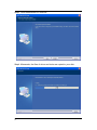
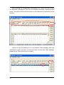
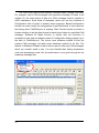
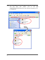
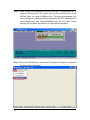
The driver installation procedure for Window XP is shown as below:
Step1: Execute PISO-CM100.exe file. Then, the installation procedure starts.
Step2: Confirm the driver installation path. This may concern with where the
demos, debug and utility tools are.
PISO-CM100 User’s Manual
18
(Version: 1.02
February 5, 2008)
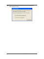
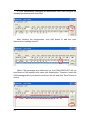
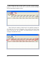
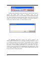
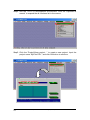
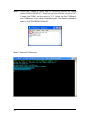
Step3: Click Install button to continue.
Step4: Afterwards, the files of driver and tools are copied to your disk.
PISO-CM100 User’s Manual
19
(Version: 1.02
February 5, 2008)
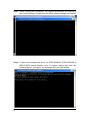
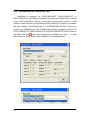
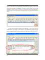
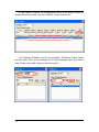
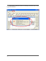
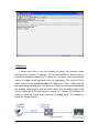
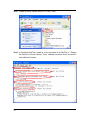
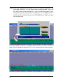
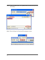
Step5: When finishing the installation, the register procedures are running in
two consult dialogs. Please wait until these consult dialogs are finished.
Step6: If users had installed the driver for PISO-CAN200, PISO-CAN400 or
PISO-CM100 series boards. One of register dialog may look like
following figure. Just ignore the message and close the dialog.
PISO-CM100 User’s Manual
20
(Version: 1.02
February 5, 2008)
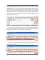
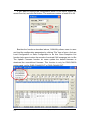
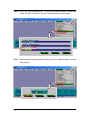
Step7: When all procedures are finished, reset your PC to enable the
PISO-CM100-D/T driver.
PISO-CM100 User’s Manual
21
(Version: 1.02
February 5, 2008)
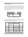
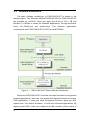
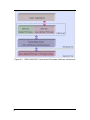
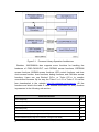
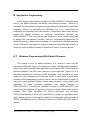
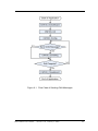
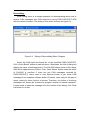
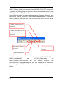
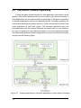
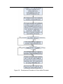
3.2 Software Architecture
The basic software architecture of PISO-CM100-D/T is shown in the
following figure. The Windows 98/Me/NT/2000/XP APIs for PISO-CM100-D/T
are provided by cm100.dll. Users can apply this dll file in VC++, VB and
Borland C++ Builder to create the Windows applications. Through the kernel
driver, KP_CM100.sys and windrvr6.sys, The Windows applications
communicate with PISO-CM100-D/T via PCI bus and DPRAM.
Figure 3.1
PISO-CM100-D/T Basic Software Architecture
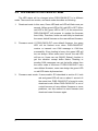
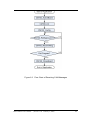
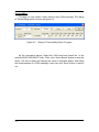
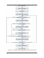
Except the PISO-CM100-D/T provides the basic functions for the general
purpose applications, users can even design their special firmware for various
CAN applications. If users just need the general functions, apply the APIs
marked with “<for default firmware>” to build their Windows applications. By
applying these APIs, users can configure the CAN controller, get the status of
PISO-CM100 User’s Manual
22
(Version: 1.02
February 5, 2008)
CAN controller, send/receive CAN messages to/from CAN bus and send CAN
messages with cyclic transmission engine. These features help users to reach
the purposes of bus monitor, bus access, network debugging, basic network
set up … and etc. The software architecture is shown below.
Figure 3.2
PISO-CM100-D/T Default Firmware Software Architecture
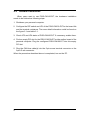
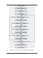
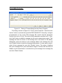
Besides, for some special applications, PISO-CM100-D/T provides the
flexibilities to arrange the user-defined firmware. This feature may be helpful
and powerful for some applications which have complex application protocols
or need to improve the system efficiency. Users can interpret the raw CAN
messages by the pre-defined application protocols on MiniOS7 platform, and
feedback the useful and simplified data to users’ Windows applications. This
software architecture can have the real-time processing feature, increase the
execution performance and efficiently reduce the PC CPU loading. The
software architecture is shown below.
PISO-CM100 User’s Manual
23
(Version: 1.02
February 5, 2008)
Figure 3.2 PISO-CM100-D/T User-defined Firmware Software Architecture
PISO-CM100 User’s Manual
24
(Version: 1.02
February 5, 2008)
4
APIs for Windows Application
In this chapter, the APIs for both default firmware and user-defined
firmware are described. The content includes the CM100.dll APIs introductions,
error code description and the simple method of troubleshooting. It is helpful to
development users’ application. The section 4.1 shows the list and information
of all APIs supported by CM100.dll. The section 4.2 shows the explication of
the return codes of the API functions. It can help users to have the basic
troubleshooting.
4.1 Windows API Definitions and Descriptions
All the functions provided by the CM100.dll are listed in the following table
and the detailed information for every function presented in the following
sub-section.
Function definition
Page Note
29
WORD CM100_GetDllVersion(void)
Int CM100_GetBoardInf(BYTE BoardNo, DWORD *dwVID, DWORD *dwDID,
DWORD *dwSVID, DWORD *dwSDID,
○△
○△
30
DWORD *dwSAuxID, DWORD *dwIrqNo)
Int CM100_TotalBoard(void)
31
○△
Int CM100_TotalCM100Board(void)
31
○△
Int CM100_TotalDNM100Board(void)
32
○△
Int CM100_TotalCPM100Board(void)
32
○△
Int CM100_GetCM100BoardSwitchNo(BYTE BoardCntNo,
BYTE *BoardSwitchNo)
Int CM100_GetDNM100BoardSwitchNo(BYTE BoardCntNo,
BYTE *BoardSwitchNo)
Int CM100_GetCPM100BoardSwitchNo(BYTE BoardCntNo,
BYTE *BoardSwitchNo)
33
34
35
○△
○△
○△
Int CM100_GetCardPortNum(BYTE BoardNo, BYTE *bGetPortNum)
36
Int CM100_ActiveBoard(BYTE BoardNo)
37 ○△
Int CM100_CloseBoard(BYTE BoardNo)
38 ○△
int CM100_BoardIsActive(BYTE BoardNo)
39 ○△
PISO-CM100 User’s Manual
25
(Version: 1.02
February 5, 2008)
○△
Function definition
Page Note
int CM100_AdujstDateTime(BYTE BoardNo)
40
○△
int CM100_Reset(BYTE BoardNo, BYTE Port)
41
○△
int CM100_Init(BYTE BoardNo, BYTE Port)
42 ○△
int CM100_HardwareReset(BYTE BoardNo, BYTE Port)
43
○△
int CM100_Check186Mode(BYTE BoardNo, BYTE *Mode)
44
○△
int CM100_Status(BYTE BoardNo, BYTE Port, BYTE *bStatus)
45
○△
47
○△
int CM100_DeleteCyclicTxMsg(BYTE BoardNo, BYTE Port, BYTE Handle)
49
○△
int CM100_EnableCyclicTxMsg(BYTE BoardNo, BYTE Port, BYTE Handle)
50
○△
int CM100_DisableCyclicTxMsg(BYTE BoardNo, BYTE Port, BYTE Handle)
51
○△
int CM100_AddCyclicTxMsg(BYTE BoardNo, BYTE Port, BYTE Mode,
DWORD MsgID, BYTE RTR, BYTE DataLen,
BYTE *Data, DWORD TimePeriod,
BYTE *Handle)
void CM100_OutputByte(BYTE BoardNo, BYTE Port, WORD wOffset,
BYTE bValue)
52
○△
BYTE CM100_InputByte(BYTE BoardNo, BYTE Port, WORD wOffset)
53
○△
int CM100_ClearSoftBuffer(BYTE BoardNo, BYTE Port)
54
○
int CM100_ClearBufferStatus(BYTE BoardNo, BYTE Port)
55
○
int CM100_ClearDataOverrun(BYTE BoardNo, BYTE Port)
56
○
int CM100_Config(BYTE BoardNo, BYTE Port, ConfigStruct *CanConfig)
57
○
60
○
61
○
62
○
64
○
66
○
67
○
int CM100_ConfigWithoutStruct(BYTE BoardNo, BYTE Port,
DWORD AccCode, DWORD AccMask,
BYTE BaudRate, BYTE BT0,
BYTE BT1)
int CM100_RxMsgCount(BYTE BoardNo, BYTE Port)
int CM100_ReceiveMsg(BYTE BoardNo, BYTE Port,
PacketStruct *CanPacket)
int CM100_ReceiveWithoutStruct(BYTE BoardNo, BYTE Port, BYTE *Mode,
DWORD *MsgID, BYTE *RTR,
BYTE *DataLen, BYTE *Data ,
DWORD *UpperTime ,
DWORD *LowerTime)
int CM100_SendMsg(BYTE BoardNo, BYTE Port, PacketStruct *CanPacket)
int CM100_SendWithoutStruct(BYTE BoardNo, BYTE Port, BYTE Mode,
DWORD MsgID, BYTE RTR, BYTE DataLen,
BYTE *Data)
PISO-CM100 User’s Manual
26
(Version: 1.02
February 5, 2008)
Function definition
Page Note
int CM100_SJA1000Config(BYTE BoardNo, BYTE Port, DWORD AccCode,
DWORD AccMask, BYTE BaudRate, BYTE BT0,
△
69
BYTE BT1)
int CM100_DPRAMInttToCM100(BYTE BoardNo, BYTE Port, BYTE Data)
int CM100_DPRAMWriteByte(BYTE BoardNo, BYTE Port, WORD Address,
BYTE Data)
int CM100_DPRAMWriteWord(BYTE BoardNo, BYTE Port, WORD Address,
WORD Data)
int CM100_DPRAMWriteDword(BYTE BoardNo, BYTE Port, WORD Address,
DWORD Data)
70
△
71
△
72
△
73
△
74
△
75
△
76
△
77
△
78
△
79
△
80
△
81
△
82
△
83
△
int CM100_DPRAMWriteMultiByte(BYTE BoardNo, BYTE Port,
WORD Address, BYTE *Data,
WORD DataNum)
int CM100_DPRAMReadByte(BYTE BoardNo, BYTE Port, WORD Address,
BYTE *Data)
int CM100_DPRAMReadWord(BYTE BoardNo, BYTE Port, WORD Address,
WORD *Data)
int CM100_DPRAMReadDword(BYTE BoardNo, BYTE Port, WORD Address,
DWORD *Data)
int CM100_DPRAMReadMultiByte(BYTE BoardNo, BYTE Port,
WORD Address, BYTE *Data,
WORD DataNum)
int CM100_DPRAMMemset(BYTE BoardNo, BYTE Port, WORD Address,
BYTE Data, WORD DataNum)
int CM100_ReceiveCmd(BYTE BoardNo, BYTE Port, BYTE *Data,
WORD *DataNum)
int CM100_SendCmd(BYTE BoardNo, BYTE Port, BYTE *Data,
WORD DataNum)
int CM100_InstallUserISR(BYTE BoardNo, void (*UserISR)(BYTE BoardNo,
BYTE InttValue))
int CM100_RemoveUserISR(BYTE BoardNo)
Table 4.1
PISO-CM100-D/T Windows APIs List
Note: In table 3.1, the mark ○ and △ indicate the valid condition of API
functions. The function marked by ○ or △ presents that this function
is useful when the PISO-CM100-D/T is default CM100 firmware inside
PISO-CM100 User’s Manual
27
(Version: 1.02
February 5, 2008)
or user-defined firmware inside respectively. If users use default
firmware, all of the functions marked by ○ could be applied. However,
if users design their own firmware by using firmware library (firmware
library is described in section 3.4), only the functions marked by △ is
useful. The functions marked with ○ △ can be used with default
firmware or in user-defined firmware.
In order to make the descriptions more simplified and clear, the attributes for
the both the input and output parameter functions are given as [input] and
[output] respectively, as shown in following table.
Keyword
Set parameter by user before Get the data from this parameter
calling this function?
after calling this function?
[ input ]
Yes
No
[ output ]
No
Yes
Table 4.2
PISO-CM100 User’s Manual
28
Description of API parameter Hint
(Version: 1.02
February 5, 2008)
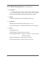
4.1.1 CM100_GetDllVersion
z
Description:
Obtain the version information of CM100.dll driver.
z
Syntax:
WORD CM100_GetDllVersion(void)
z
Parameter:
None
z
Return:
DLL version information. For example: If 100(hex) is return, it means
driver version is 1.00.
PISO-CM100 User’s Manual
29
(Version: 1.02
February 5, 2008)
4.1.2 CM100_GetBoardInf
z
Description:
Obtain the information of PISO-CM100-D/T, PISO-DNM100-D/T or
PISO-CPM100-D/T, which include vender ID, device ID and interrupt
number.
z
Syntax:
int CM100_GetBoardInf(BYTE BoardNo, DWORD *dwVID,
DWORD *dwDID, DWORD *dwSVID,
DWORD *dwSDID, DWORD *dwSAuxID,
DWORD *dwIrqNo)
z
Parameter:
BoardNo: [input] Switch No of PISO-CM100-D/T, PISO-DNM100-D/T or
PISO-CPM100-D/T DIP. The value is from 0 to 15.
*dwVID: [output] The address of a variable which is used to receive the
vendor ID.
*dwDID: [output] The address of a variable used to receive device ID.
*dwSVID: [output] The address of a variable applied to receive
sub-vendor ID.
*dwSDID: [output] The address of a variable applied to receive
sub-device ID.
*dwSAuxID: [output] The address of a variable used to receive
sub-auxiliary ID.
*dwIrqNo: [output] The address of a variable used to receive logical
interrupt number.
z
Return:
CM100_NoError: OK
CM100_DriverError: Kernel driver is not opened.
CM100_BoardNumberError: BoardNo exceeds the current scanned
total board numbers.
PISO-CM100 User’s Manual
30
(Version: 1.02
February 5, 2008)
4.1.3 CM100_TotalBoard
z
Description:
Obtain the total board number of PISO-CM100-D/T,
PISO-DNM100- D/T, and PISO-CPM100-D/T boards installed in the PCI
bus.
z
Syntax:
Int CM100_TotalBoard(void)
z
Parameter:
None
z
Return:
Return the scanned total board number.
4.1.4 CM100_TotalCM100Board
z
Description:
Obtain the total board number of PISO-CM100-D/T installed in the
PCI bus.
z
Syntax:
Int CM100_TotalCM100Board(void)
z
Parameter:
None
z
Return:
Return the scanned total PISO-CM100-D/T number.
PISO-CM100 User’s Manual
31
(Version: 1.02
February 5, 2008)
4.1.5 CM100_TotalDNM100Board
z
Description:
Obtain the total board number of PISO-DNM100-D/T installed in the
PCI bus.
z
Syntax:
Int CM100_TotalDNM100Board(void)
z
Parameter:
None
z
Return:
Return the scanned total PISO-DNM100-D/T number.
4.1.6 CM100_TotalCPM100Board
z
Description:
Obtain the total board number of PISO-CPM100-D/T plugged in the
PCI bus.
z
Syntax:
Int CM100_TotalCPM100Board(void)
z
Parameter:
None
z
Return:
Return the scanned total PISO-CPM100-D/T number.
PISO-CM100 User’s Manual
32
(Version: 1.02
February 5, 2008)
4.1.7 CM100_GetCM100BoardSwitchNo
z
Description:
Obtain the DIP switch No. of PISO-CM100-D/T.
z
Syntax:
Int CM100_GetCM100BoardSwitchNo(BYTE BoardCntNo,
BYTE *BoardSwitchNo)
z
Parameter:
BoardCntNo: [input] The number of specified PISO-CM100-D/T. For
example, if the first PISO-CM100-D/T is applied, this
value is 0. If the second board is applied, this value is 1.
* BoardSwitchNo: [output] The address of a variable used to get the DIP
switch No. of PISO-CM100-D/T.
z
Return:
CM100_NoError: OK
CM100_DriverError: Kernel driver is not opened.
CM100_BoardNumberError: BoardNo exceeds the current scanned
total board numbers.
PISO-CM100 User’s Manual
33
(Version: 1.02
February 5, 2008)
4.1.8 CM100_GetDNM100BoardSwitchNo
z
Description:
Obtain the DIP switch No. of PISO-DNM100-D/T.
z
Syntax:
Int CM100_GetDNM100BoardSwitchNo(BYTE BoardCntNo,
BYTE *BoardSwitchNo)
z
Parameter:
BoardCntNo: [input] The number of specified PISO-DNM100-D/T. For
example, if the first PISO-DNM100-D/T is applied, this
value is 0. If the second board is applied, this value is 1.
* BoardSwitchNo: [output] The address of a variable used to get the DIP
switch No. of PISO-DNM100-D/T.
z
Return:
CM100_NoError: OK
CM100_DriverError: Kernel driver is not opened.
CM100_BoardNumberError: BoardNo exceeds the current scanned
total board number.
PISO-CM100 User’s Manual
34
(Version: 1.02
February 5, 2008)
4.1.9 CM100_GetCPM100BoardSwitchNo
z
Description:
Obtain the DIP switch No. of PISO-CPM100-D/T installed in the
PCI bus.
z
Syntax:
Int CM100_GetCPM100BoardSwitchNo(BYTE BoardCntNo,
BYTE *BoardSwitchNo)
z
Parameter:
BoardCntNo: [input] The number of specified PISO-DNM100-D/T. For
example, if the first PISO-DNM100-D/T is applied, this
value is 0. If the second board is applied, this value is 1.
* BoardSwitchNo: [output] The address of a variable used to get the DIP
switch No. of PISO-CPM100-D/T.
z
Return:
CM100_NoError: OK
CM100_DriverError: Kernel driver is not opened.
CM100_BoardNumberError: BoardNo exceeds the current scanned
total board numbers.
PISO-CM100 User’s Manual
35
(Version: 1.02
February 5, 2008)
4.1.10 CM100_GetCardPortNum
z
Description:
Obtain the port numbers of PISO-CM100-D/T, PISO-DNM100-D/T,
or PISO-CPM100-D/T installed in the PCI bus.
z
Syntax:
Int CM100_GetCardPortNum(BYTE BoardNo, BYTE *bGetPortNum)
z
Parameter:
BoardNo: [input] Switch No of PISO-CM100-D/T, PISO-DNM100-D/T or
PISO-CPM100-D/T DIP. The value is from 0 to 15.
* bGetPortNum: [output] The address of a variable used to obtain the
port numbers of PISO-CM100-D/T.
z
Return:
CM100_NoError: OK
CM100_DriverError: Kernel driver is not opened.
CM100_BoardNumberError: BoardNo exceeds the current scanned
total board numbers.
PISO-CM100 User’s Manual
36
(Version: 1.02
February 5, 2008)
4.1.11 CM100_ActiveBoard
z
Description:
Activate PISO-CM100-D/T. It must be called once before using the
other functions of PISO-CM100-D/T APIs.
z
Syntax:
int
z
CM100_ActiveBoard(BYTE BoardNo)
Parameter:
BoardNo: [input] PISO-CM100-D/T DIP switch No. (0~15).
z
Return:
CM100_NoError: OK
CM100_DriverError: Kernel driver is not opened.
CM100_BoardNumberError: BoardNo exceeds the current scanned
total board numbers.
CM100_ActiveBoardError: This board can not be activated or kernel
driver can not be found.
PISO-CM100 User’s Manual
37
(Version: 1.02
February 5, 2008)
4.1.12 CM100_CloseBoard
z
Description:
Stop and close the kernel driver and release the device resource
from computer device resource. This method must be called once
before exiting the user’s application program.
z
Syntax:
int
z
CM100_CloseBoard(BYTE BoardNo)
Parameter:
BoardNo: [input] PISO-CM100-D/T DIP switch No. (0~15).
z
Return:
CM100_NoError: OK
CM100_DriverError: Kernel driver is not opened.
CM100_BoardNumberError: BoardNo exceeds the current scanned
total board numbers.
PISO-CM100 User’s Manual
38
(Version: 1.02
February 5, 2008)
4.1.13 CM100_BoardIsActive
z
Description:
Obtain the active status of the specific board.
z
Syntax:
int
z
CM100_BoardIsActive(BYTE BoardNo)
Parameter:
BoardNo: [input] PISO-CM100-D/T DIP switch No. (0~15).
z
Return:
0: means the board is inactive.
1: means the board is active.
PISO-CM100 User’s Manual
39
(Version: 1.02
February 5, 2008)
4.1.14 CM100_ AdujstDateTime
z
Description:
Adjust date and time of PISO-CM100-D/T by using PC time.
z
Syntax:
int CM100_AdujstDateTime(BYTE BoardNo)
z
Parameter:
BoardNo: [input] PISO-CM100-D/T DIP switch No. (0~15).
z
Return:
CM100_NoError: OK
CM100_DriverError: Kernel driver is not opened.
CM100_BoardNumberError: BoardNo exceeds the current scanned
total board numbers.
CM100_ActiveBoardError: This board is not activated.
CM100_SetDateTimeFailure: Set date and time failure.
PISO-CM100 User’s Manual
40
(Version: 1.02
February 5, 2008)
4.1.15 CM100_Reset
z
Description:
Reset the CAN controller, SJA1000, of the PISO-CM100-D/T.
z
Syntax:
int
z
CM100_Reset(BYTE BoardNo, BYTE Port)
Parameter:
BoardNo: [input] PISO-CM100-D/T DIP switch No. (0~15).
Port: [input] CAN port No. For PISO-CM100-D/T, this value is always 1.
z
Return:
CM100_NoError: OK
CM100_DriverError: Kernel driver is not opened.
CM100_BoardNumberError: BoardNo exceeds the current scanned
total board numbers.
CM100_ActiveBoardError: This board is not activated.
CM100_PortNumberError: Port number is not correct.
PISO-CM100 User’s Manual
41
(Version: 1.02
February 5, 2008)
4.1.16 CM100_Init
z
Description:
Initiate the CAN controller.
z
Syntax:
int CM100_Init(BYTE BoardNo, BYTE Port)
z
Parameter:
BoardNo: [input] PISO-CM100-D/T DIP switch No. (0~15).
Port: [input] CAN port No. For PISO-CM100-D/T, this value is always 1.
z
Return:
CM100_NoError: OK
CM100_DriverError: Kernel driver is not opened.
CM100_BoardNumberError: BoardNo exceeds the current scanned
total board numbers.
CM100_ActiveBoardError: This board is not activated.
CM100_PortNumberError: Port number is not correct.
CM100_TimeOut: The PISO-CM100-D/T has no response.
CM100_ModeError: This board is in download mode, and can’t be
changed to firmware mode.
PISO-CM100 User’s Manual
42
(Version: 1.02
February 5, 2008)
4.1.17 CM100_HardwareReset
z
Description:
Reset the PISO-CM100 hardware, such as CAN controller, DPRAM,
186 CPU, …, and so forth.
z
Syntax:
int CM100_HardwareReset(BYTE BoardNo, BYTE Port)
z
Parameter:
BoardNo: [input] PISO-CM100-D/T DIP switch No. (0~15).
Port: [input] CAN port No. For PISO-CM100-D/T, this value is always 1.
z
Return:
CM100_NoError: OK
CM100_DriverError: Kernel driver is not opened.
CM100_BoardNumberError: BoardNo exceeds the current scanned
total board numbers.
CM100_ActiveBoardError: This board is not activated.
CM100_PortNumberError: Port number is not correct.
CM100_TimeOut: The PISO-CM100-D/T has no response.
CM100_ModeError: This board is in download mode, and can’t be
changed to firmware mode.
PISO-CM100 User’s Manual
43
(Version: 1.02
February 5, 2008)
4.1.18 CM100_Check186Mode
z
Description:
Obtain the specified PISO-CM100-D/T if it is in download mode or
in firmware mode.
z
Syntax:
int CM100_Check186Mode(BYTE BoardNo, BYTE *Mode)
z
Parameter:
BoardNo: [input] PISO-CM100-D/T DIP switch No. (0~15).
*Mode: [output] The address of a variable used to get the
PISO-CM100-D/T mode. If this value is 0, it indicates that the
PISO-CM100-D/T is in download mode. If 1, it is in firmware
mode. When PISO-CM100-D/T is in download mode, it can
only update the firmware and the firmware will not work at the
same time. Users can use CM100_Init() function to set the
PISO-CM100-D/T into firmware mode.
z
Return:
CM100_NoError: OK
CM100_DriverError: Kernel driver is not opened.
CM100_BoardNumberError: BoardNo exceeds the current scanned
total board numbers.
CM100_ActiveBoardError: This board is not activated.
CM100_TimeOut: The PISO-CM100-D/T has no response.
CM100_InitError: The PISO-CM100-D/T replies erroneously.
CM100_ModeError: This board is in download mode, and can’t be
changed to firmware mode.
PISO-CM100 User’s Manual
44
(Version: 1.02
February 5, 2008)
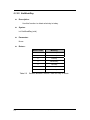
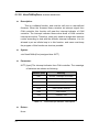
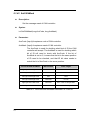
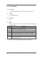
4.1.19 CM100_Status
z
Description:
Obtain the status of the CAN controller for the specific
PISO-CM100-D/T400/200 board.
z
Syntax:
int
z
CM100_Status(BYTE BoardNo, BYTE Port, BYTE *bStatus)
Parameter:
BoardNo: [input] PISO-CM100-D/T DIP switch No. (0~15).
Port: [input] CAN port No. For PISO-CM100-D/T, this value is always 1.
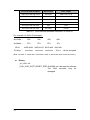
*bStatus: [output] The address of a variable is applied to get the status
value of CAN controller.
Bit
NAME
bit 7
Bus Status
bit 6
Error Status
bit 5
Transmit Status
bit 4
Receive Status
bit 3
Transmission Complete Status
bit 2
Transmit Buffer Status
bit 1
Data Overrun Status
bit 0
Receive Buffer Status
Table 4.3
PISO-CM100 User’s Manual
45
VALUE
STATUS
1
bus-off
0
bus-on
1
error
0
ok
1
transmit
0
idle
1
receive
0
idle
1
complete
0
incomplete
1
release
0
locked
1
overrun
0
absent
1
full/not empty
0
empty
Bit interpretation of the bStatus.
(Version: 1.02
February 5, 2008)
z
Return:
CM100_NoError: OK
CM100_DriverError: Kernel driver is not opened.
CM100_BoardNumberError: BoardNo exceeds the current scanned
total board numbers.
CM100_ActiveBoardError: This board is not activated.
CM100_PortNumberError: Port number is not correct.
PISO-CM100 User’s Manual
46
(Version: 1.02
February 5, 2008)
4.1.20 CM100_AddCyclicTxMsg
z
Description:
Add a cyclic transmission message into cm100 firmware.
Afterwards, uses can enable or disable this cyclic transmission
messages
by
using
CM100_EnableCyclicTxMsg()
and
CM100_DelectCyclicTxMsg() functions. The maximum number of the
transmission messages is 5. After adding a cyclic transmission
message, the handle for this message will be returned. The less value
of handle indicates the higher priority of this cyclic transmission
message.
z
Syntax:
int CM100_AddCyclicTxMsg(BYTE BoardNo, BYTE Port, BYTE Mode,
DWORD MsgID, BYTE RTR,
BYTE DataLen, BYTE *Data,
DWORD TimePeriod, BYTE *Handle)
z
Parameter:
BoardNo: [input] PISO-CM100-D/T DIP switch No. (0~15).
Port: [input] CAN port No. For PISO-CM100-D/T, this value is always 1.
Mode: [input] 0 for 11-bit message ID, 1 for 29-bit message ID.
MsgID: [input] CAN message ID.
RTR: [input] Set remote-transmit-request is used or not. 0 is for useless,
1 is for useful.
DataLen: [input] CAN message data length. The maximum value is 8.
*Data: [input] The start address of the data buffer of a CAN message.
The maximum space of *Data is 8 bytes.
TimePeriod: [input] The time period of cyclic transmission. This
parameter is formatted by 0.1ms. The minimum value is 5.
PISO-CM100 User’s Manual
47
(Version: 1.02
February 5, 2008)
*Handle: [output] The address of a variable is used to get the handle of
a cyclic transmission. When users want to enable or disable
the specified cyclic transmission, this value must be needed.
z
Return:
CM100_NoError: OK
CM100_DriverError: Kernel driver is not opened.
CM100_BoardNumberError: BoardNo exceeds the current scanned
total board numbers.
CM100_ActiveBoardError: This board is not activated.
CM100_PortNumberError: Port number is not correct.
CM100_TimeOut: The PISO-CM100-D/T has no response.
CM100_SetCyclicMsgFailure: The cyclic transmission messages are
over 5 messages or PISO-CM100-D/T
replies erroneously.
PISO-CM100 User’s Manual
48
(Version: 1.02
February 5, 2008)
4.1.21 CM100_DeleteCyclicTxMsg
z
Description:
Remove the specified cyclic transmission message which is added
by CM100_AddCyclicTxMsg() function.
z
Syntax:
int CM100_DeleteCyclicTxMsg(BYTE BoardNo, BYTE Port,
BYTE Handle)
z
Parameter:
BoardNo: [input] PISO-CM100-D/T DIP switch No. (0~15).
Port: [input] CAN port No. For PISO-CM100-D/T, this value is always 1.
Handle: [input] The handle of cyclic transmission message which is
obtained by CM100_AddCyclicTxMsg() function.
z
Return:
CM100_NoError: OK
CM100_DriverError: Kernel driver is not opened.
CM100_BoardNumberError: BoardNo exceeds the current scanned
total board numbers.
CM100_ActiveBoardError: This board is not activated.
CM100_PortNumberError: Port number is not correct.
CM100_TimeOut: The PISO-CM100-D/T has no response.
CM100_SetCyclicMsgFailure:
The
PISO-CM100-D/T
erroneously.
PISO-CM100 User’s Manual
49
(Version: 1.02
February 5, 2008)
replies
4.1.22 CM100_EnableCyclicTxMsg
z
Description:
Enable the cyclic transmission message which is added by
CM100_AddCyclicTxMsg() function before. After enabling the specified
cyclic transmission message, PISO-CM100-D/T will transmit the
specified CAN message by configured time period.
z
Syntax:
int CM100_EnableCyclicTxMsg(BYTE BoardNo, BYTE Port,
BYTE Handle)
z
Parameter:
BoardNo: [input] PISO-CM100-D/T DIP switch No. (0~15).
Port: [input] CAN port No. For PISO-CM100-D/T, this value is always 1.
Handle: [input] The handle of cyclic transmission message which is
obtained by CM100_AddCyclicTxMsg() function.
z
Return:
CM100_NoError: OK
CM100_DriverError: Kernel driver is not opened.
CM100_BoardNumberError: BoardNo exceeds the current scanned
total board numbers.
CM100_ActiveBoardError: This board is not activated.
CM100_PortNumberError: Port number is not correct.
CM100_TimeOut: The PISO-CM100-D/T has no response.
CM100_SetCyclicMsgFailure:
The
PISO-CM100-D/T
erroneously.
PISO-CM100 User’s Manual
50
(Version: 1.02
February 5, 2008)
replies
4.1.23 CM100_DisableCyclicTxMsg
z
Description:
Disable the cyclic transmission message which is enabled by
CM100_EnableCyclicTxMsg() function.
z
Syntax:
int CM100_DisableCyclicTxMsg(BYTE BoardNo, BYTE Port,
BYTE Handle)
z
Parameter:
BoardNo: [input] PISO-CM100-D/T DIP switch No. (0~15).
Port: [input] CAN port No. For PISO-CM100-D/T, this value is always 1.
Handle: [input] The handle of cyclic transmission message which is
obtained by CM100_AddCyclicTxMsg() function.
z
Return:
CM100_NoError: OK
CM100_DriverError: Kernel driver is not opened.
CM100_BoardNumberError: BoardNo exceeds the current scanned
total board numbers.
CM100_ActiveBoardError: This board is not activated.
CM100_PortNumberError: Port number is not correct.
CM100_TimeOut: The PISO-CM100-D/T has no response.
CM100_SetCyclicMsgFailure:
The
PISO-CM100-D/T
erroneously.
PISO-CM100 User’s Manual
51
(Version: 1.02
February 5, 2008)
replies
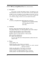
4.1.24 CM100_OutputByte
z
Description:
Write the data to the specified CAN controller register, SJA1000
register, of the PISO-CM100-D/T.
z
Syntax:
void CM100_OutputByte(BYTE BoardNo, BYTE Port, WORD wOffset,
BYTE bValue)
z
Parameter:
BoardNo: [input] PISO-CM100-D/T DIP switch No. (0~15).
Port: [input] CAN port No. For PISO-CM100-D/T, this value is always 1.
wOffset: [input] The register address of SJA1000.
bValue: [input] The value written to the specified register.
z
Return:
None
PISO-CM100 User’s Manual
52
(Version: 1.02
February 5, 2008)
4.1.25 CM100_InputByte
z
Description:
Read the data from the specified CAN controller register, SJA1000
register, of the PISO-CM100-D/T.
z
Syntax:
BYTE CM100_InputByte(BYTE BoardNo, BYTE Port, WORD wOffset)
z
Parameter:
BoardNo: [input] PISO-CM100-D/T DIP switch No. (0~15).
Port: [input] CAN port No. For PISO-CM100-D/T, this value is always 1.
wOffset: [input] The register address of SJA1000.
z
Return:
The value read from the specified register.
PISO-CM100 User’s Manual
53
(Version: 1.02
February 5, 2008)
4.1.26 CM100_ClearSoftBuffer <For default firmware>
z
Description:
Clear the software buffer of the PISO-CM100-D/T. When users use
these functions, CM100_SendMsg(), CM100_SendWithoutStruct(),
CM100_ReceiveMsg() or CM100_ReceiveWithoutStuct(), and get the
error code, CM100_SoftBufferIsFull, this function may be needed.
z
Syntax:
int CM100_ClearSoftBuffer(BYTE BoardNo, BYTE Port)
z
Parameter:
BoardNo: [input] PISO-CM100-D/T DIP switch No. (0~15).
Port: [input] CAN port No. For PISO-CM100-D/T, this value is always 1.
z
Return:
CM100_NoError: OK
CM100_DriverError: Kernel driver is not opened.
CM100_BoardNumberError: BoardNo exceeds the current scanned
total board numbers.
CM100_ActiveBoardError: This board is not activated.
CM100_PortNumberError: The port number is not correct.
CM100_TimeOut: The PISO-CM100-D/T has no response.
PISO-CM100 User’s Manual
54
(Version: 1.02
February 5, 2008)
4.1.27 CM100_ClearBufferStatus <For default firmware>
z
Description:
Clear the software buffer of the PISO-CM100-D/T. When users use
these functions, CM100_SendMsg(), CM100_SendWithoutStruct(),
CM100_ReceiveMsg() or CM100_ReceiveWithoutStuct(), and get the
error code, CM100_SoftBufferIsFull, this function may be needed.
z
Syntax:
int CM100_ClearBufferStatus(BYTE BoardNo, BYTE Port)
z
Parameter:
BoardNo: [input] PISO-CM100-D/T DIP switch No. (0~15).
Port: [input] CAN port No. For PISO-CM100-D/T, this value is always 1.
z
Return:
CM100_NoError: OK
CM100_DriverError: Kernel driver is not opened.
CM100_BoardNumberError: BoardNo exceeds the current scanned
total board numbers.
CM100_ActiveBoardError: This board is not activated.
CM100_PortNumberError: Port number is not correct.
CM100_TimeOut: The PISO-CM100-D/T has no response.
PISO-CM100 User’s Manual
55
(Version: 1.02
February 5, 2008)
4.1.28 CM100_ClearDataOverrun <For default firmware>
z
Description:
Clear the data overrun status of CAN controller, SJA1000. When
users use CM100_Status() to get the status value of CAN controller. If
users obtain the data status is ON, this function may be needed.
z
Syntax:
int CM100_ClearDataOverrun(BYTE BoardNo, BYTE Port)
z
Parameter:
BoardNo: [input] PISO-CM100-D/T DIP switch No. (0~15).
Port: [input] CAN port No. For PISO-CM100-D/T, this value is always 1.
z
Return:
CM100_NoError: OK
CM100_DriverError: Kernel driver is not opened.
CM100_BoardNumberError: BoardNo exceeds the current scanned
total board numbers.
CM100_ActiveBoardError: This board is not activated.
CM100_PortNumberError: The port number is not correct.
PISO-CM100 User’s Manual
56
(Version: 1.02
February 5, 2008)
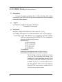
4.1.29 CM100_Config <For default firmware>
z
Description:
Configure the baud, message filter of CAN controller. After calling
this function, the PISO-CM100 can start to send/receive CAN messages
to/from the CAN network.
z
Syntax:
int CM100_Config(BYTE BoardNo, BYTE Port,
ConfigStruct *CanConfig)
z
Parameter:
BoardNo: [input] PISO-CM100-D/T DIP switch No. (0~15).
Port: [input] CAN port No. For PISO-CM100-D/T, this value is always 1.
* CanConfig: [input] The address of a ConfigStruct structure variable
used to configure the PISO-CM100-D/T. The ConfigStruct
structure is defined as following:
typedef struct{
BYTE AccCode[4];
BYTE AccMask[4];
BYTE BaudRate;
BYTE BT0,BT1;
} ConfigStruct;
AccCode[4]: Acceptance code of CAN controller.
AccMask[4]: Acceptance mask of CAN controller.
The AccCode is used for deciding what kind
of ID the CAN controller will accept. The
AccMask is used for deciding which bit of ID
will need to check with AccCode. If the bit of
AccMask is set to 0, it means that the bit in
the same position of ID need to be checked,
and that ID bit value needs to match the bit of
AccCode in the same position.
PISO-CM100 User’s Manual
57
(Version: 1.02
February 5, 2008)
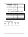
AccCode and AccMask
Bit Position
Filter Target
high byte of the high word
bit7~bit0
bit10 ~ bit3 of ID
low byte of the high word
bit7~bit5
bit2 ~ bit0 of ID
low byte of the high word
bit4
RTR
low byte of the high word
bit3~bit0
no use
high byte of the low word
bit7~bit0
bit7 ~ bit0 of 1st byte data
low byte of the low word
bit7~bit0
bit7 ~ bit0 of 2nd byte data
Table 4.4
AccCode and AccMask Definition For 11-bit ID
AccCode and AccMask
Bit Position
Filter Target
high byte of the high word
bit7~bit0
bit28~ bit21 of ID
low byte of the high word
bit7~bit0
bit20 ~ bit13 of ID
high byte of the low word
bit7~bit0
bit12 ~ bit5 of ID
low byte of the low word
bit7~bit3
bit4 ~ bit0 of ID
low byte of the low word
bit2
RTR
low byte of the low word
bit1~bit0
no use
Table 4.5
AccCode and AccMask Definition For 29-bit ID
For example (In 29 bit ID message):
Array[0]
Array[1]
Array[2]
Array[3]
AccCode :
00h
00h
00h
A0h
AccMask :
FFh
FFh
FFh
1Fh
ID bit
ID Value
bit28~bit21 bit20~bit13 bit12~bit5 bit4~bit0
: xxxx xxxx
xxxx xxxx
xxxx xxxx
101x x
will be accepted
(Note: The mark “x” means don’t care. And the mark “h” behind the value means hex format.)
PISO-CM100 User’s Manual
58
(Version: 1.02
February 5, 2008)
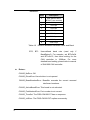
BaudRate:
Table 4.6
BT0,
z
Value
Description
0
User-defined baud
(BT0,BT1 are needed)
1
10 K bps
2
20 K bps
3
50 K bps
4
125 K bps
5
250 K bps
6
500 K bps
7
800 K bps
8
1000 K bps
Relation Between BaudRate value and Baud
BT1:
User-defined baud rate (used only if
BaudRate=0). For example, set BT0=0x04
and BT1=0x1C, then baud setting for the
CAN controller is 100Kbps. For more
detailed baud setting, please refer to manual
of SJA1000 CAN controller.
Return:
CM100_NoError: OK
CM100_DriverError: Kernel driver is not opened.
CM100_BoardNumberError: BoardNo exceeds the current scanned
total board numbers.
CM100_ActiveBoardError: This board is not activated.
CM100_PortNumberError: Port number is not correct.
CM100_TimeOut: The PISO-CM100-D/T has no response.
CM100_InitError: The PISO-CM100-D/T replies erroneously.
PISO-CM100 User’s Manual
59
(Version: 1.02
February 5, 2008)
4.1.30 CM100_ConfigWithoutStruct <For default firmware>
z
Description:
This function is similar with CM100_Config(). The difference is the
input parameters of function. This function uses no structure parameter
so that it is easy to be applied in some program environment, such as
VB. Therefore, about the input parameters of this function, please refer
to the CM100_Config() function for the more detailed information.
z
Syntax:
int CM100_ConfigWithoutStruct(BYTE BoardNo, BYTE Port,
DWORD AccCode, DWORD AccMask,
BYTE BaudRate, BYTE BT0,
BYTE BT1)
z
Parameter:
BoardNo: [input] PISO-CM100-D/T DIP switch No. (0~15).
Port: [input] CAN port No. For PISO-CM100-D/T, this value is always 1.
AccCode: [input] Acceptance code of CAN controller.
AccMask: [input] Acceptance mask of CAN controller.
BaudRate: [input] The baud indicator of CAN controller.
BT0: [input] User-defined baud.
BT1: [input] User-defined baud.
For more information about these parameters, please refer to the
section 3.2.28.
z
Return:
CM100_NoError: OK
CM100_DriverError: Kernel driver is not opened.
CM100_BoardNumberError: BoardNo exceeds the current scanned
total board numbers.
CM100_ActiveBoardError: This board is not activated.
CM100_PortNumberError: Port number is not correct.
CM100_TimeOut: The PISO-CM100-D/T has no response.
CM100_InitError: The PISO-CM100-D/T replies erroneously.
PISO-CM100 User’s Manual
60
(Version: 1.02
February 5, 2008)
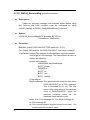
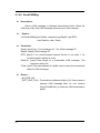
4.1.31 CM100_RxMsgCount <For default firmware>
z
Description:
Obtain the number of CAN messages available in the reception
software buffer.
z
Syntax:
int CM100_RxMsgCount(BYTE BoardNo, BYTE Port)
z
Parameter:
BoardNo: [input] PISO-CM100-D/T DIP switch No. (0~15).
Port: [input] CAN port No. For PISO-CM100-D/T, this value is always 1.
z
Return:
The number of CAN messages in software buffer.
PISO-CM100 User’s Manual
61
(Version: 1.02
February 5, 2008)
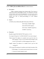
4.1.32 CM100_ReceiveMsg <For default firmware>
z
Description:
Obtain the received message from software buffer. Before using
this function, the CAN controller must be configured by using
CM100_Config() or CM100_ConfigWithoutStruct() functions.
z
Syntax:
int CM100_ReceiveMsg(BYTE BoardNo, BYTE Port,
PacketStruct *CanPacket)
z
Parameter:
BoardNo: [input] PISO-CM100-D/T DIP switch No. (0~15).
Port: [input] CAN port No. For PISO-CM100-D/T, this value is always 1.
*CanPacket: [output] The address of a PacketStruct structure variable
used to get a CAN message. The PacketStruct structure is
defined as following:
typedef struct packet{
LONGLONG MsgTimeStamps;
BYTE mode;
DWORD id;
BYTE rtr;
BYTE len;
BYTE data[8];
} PacketStruct;
MsgTimeStamps: This parameter will record the time when
PISO-CM100-D/T got a CAN message.
This is formatted by 0.1 ms. The time
base of this value refers to the hardware
clock of PISO-CM100-D/T. When the
personal computer boots up, the
hardware clock starts to count.
mode: 0 for 11-bit message ID, 1 for 29-bit message ID.
id: CAN message ID.
rtr: 0 for remote-transmit-request format is not used, 1 for
remote-transmit-request is used.
PISO-CM100 User’s Manual
62
(Version: 1.02
February 5, 2008)
len: Data length of a CAN message
data[8]: data of a CAN message
z
Return:
CM100_NoError: OK
CM100_DriverError: Kernel driver is not opened.
CM100_BoardNumberError: BoardNo exceeds the current scanned
total board numbers.
CM100_ActiveBoardError: This board is not activated.
CM100_PortNumberError: Port number is not correct.
CM100_SoftBufferIsEmpty: There is no CAN message in reception
software buffer.
CM100_SoftBufferIsFull: Users can still get CAN message from the
reception software buffer, but the software
buffer is overflow.
CM100_TimeOut: The PISO-CM100-D/T has no response.
PISO-CM100 User’s Manual
63
(Version: 1.02
February 5, 2008)
4.1.33 CM100_ReceiveWithoutStruct <For default firmware>
z
Description:
Obtain a received message from software buffer. This function is
similar with CM100_ReceiveMsg() function. The difference is that this
function doesn’t use any structure parameter. It is easy to use in some
program environment, such as VB. Therefore, the input parameters of
function can refer to CM100_ReceiveMsg() for more detailed
information.
z
Syntax:
int CM100_ReceiveWithoutStruct(BYTE BoardNo, BYTE Port,
BYTE *Mode, DWORD *MsgID,
BYTE *RTR, BYTE *DataLen,
BYTE *Data , DWORD *UpperTime ,
DWORD *LowerTime)
z
Parameter:
BoardNo: [input] PISO-CM100-D/T DIP switch No. (0~15).
Port: [input] CAN port No. For PISO-CM100-D/T, this value is always 1.
*Mode: [output] The address of a variable used to get the mode of a
CAN message. If value is 0, the received CAN message is with
11-bit ID. The 29-bit ID of a CAN message will have value 1.
*MsgID: [output] The address of a variable used to get the CAN
message ID.
*RTR: [output] The address of a variable used to obtain the status of this
CAN message. 0 for remote-transmit-request format is not used,
1 for remote- transmit-request is used.
PISO-CM100 User’s Manual
64
(Version: 1.02
February 5, 2008)
*DataLen: [output] The address of a variable used to obtain the data
length of a CAN message. The range of this value is from 0
to 8.
*Data: [output] The start address of a buffer used to get the data of a
CAN message. Users need to put an 8-byte element array in this
filed.
*UpperTime: [output] The address of a variable used to obtain the
higher double-word of time stamp of a CAN message.
*LowerTime: [output] The address of a variable used to obtain the lower
double-word of time stamp of a CAN message. The unit of
UpperTime and LowerTime are 0.1ms.
z
Return:
CM100_NoError: OK
CM100_DriverError: Kernel driver is not opened.
CM100_BoardNumberError: BoardNo exceeds the current scanned
total board numbers.
CM100_ActiveBoardError: This board is not activated.
CM100_PortNumberError: Port number is not correct.
CM100_SoftBufferIsEmpty: There is no CAN message in reception
software buffer.
CM100_SoftBufferIsFull: Users can still get CAN message from the
reception software buffer, but the software
buffer is overflow.
CM100_TimeOut: The PISO-CM100-D/T has no response.
PISO-CM100 User’s Manual
65
(Version: 1.02
February 5, 2008)
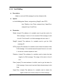
4.1.34 CM100_SendMsg <For default firmware>
z
Description:
Send a CAN message to software transmission buffer. When the
CAN bus is idle, this CAN message will be sent to CAN network. Note
that if users make some mistakes of CAN bus wiring and configuration,
the CAN messages may not be transmitted successfully. In this case,
the messages sent by users will be put in the transmission buffer. Users
can use the API CM100_Status to check if any error is happen.
z
Syntax:
int CM100_SendMsg(BYTE BoardNo, BYTE Port,
PacketStruct *CanPacket)
z
Parameter:
BoardNo: [input] PISO-CM100-D/T DIP switch No. (0~15).
Port: [input] CAN port No. For PISO-CM100-D/T, this value is always 1.
*CanPacket: [input] The address of a PacketStruct structure variable
used to describe the sent CAN message. About the
definition of PacketStruct, please refer to the description of
CM100_ReceiveMsg() function.
z
Return:
CM100_NoError: OK
CM100_DriverError: Kernel driver is not opened.
CM100_BoardNumberError: BoardNo exceeds the current scanned
total board numbers.
CM100_ActiveBoardError: This board is not activated.
CM100_PortNumberError: Port number is not correct.
CM100_TimeOut: The PISO-CM100-D/T has no response.
CM100_SoftBufferIsFull: The transmission software buffer is overflow.
PISO-CM100 User’s Manual
66
(Version: 1.02
February 5, 2008)
4.1.35 CM100_SendWithoutStruct <For default firmware>
z
Description:
Send a CAN message to software transmission buffer. When the
CAN bus is idle, this CAN message will be sent to CAN network. This
function is similar with CM100_SendMsg() function. The difference is
that this function doesn’t use any structure parameter. It is easy to use
in some program environment, such as VB. Therefore, the input
parameters of function can refer to CM100_SendMsg() for more
detailed information. Note that if users make some mistakes of CAN bus
wiring and configuration, the CAN messages may not be transmitted
successfully. In this case, the messages sent by users will be put in the
transmission buffer. Users can use the API CM100_Status to check if
any error is happen.
z
Syntax:
int CM100_SendWithoutStruct(BYTE BoardNo, BYTE Port, BYTE Mode,
DWORD MsgID, BYTE RTR,
BYTE DataLen, BYTE *Data)
z
Parameter:
BoardNo: [input] PISO-CM100-D/T DIP switch No. (0~15).
Port: [input] CAN port No. For PISO-CM100-D/T, this value is always 1.
Mode: [input] 0 for 11-bit message ID, 1 for 29-bit message ID.
MsgID: [input] CAN message ID.
RTR: [input] 0 for remote-transmit-request format is not used, 1 for
remote-transmit-request is used.
PISO-CM100 User’s Manual
67
(Version: 1.02
February 5, 2008)
DataLen: [input] Data length of a transmitted CAN message. The
maximum value is 8.
*Data: [input] The start address of a buffer is used to store the
transmitted data of a CAN message.
z
Return:
CM100_NoError: OK
CM100_DriverError: Kernel driver is not opened.
CM100_BoardNumberError: BoardNo exceeds the current scanned
total board numbers.
CM100_ActiveBoardError: This board is not activated.
CM100_PortNumberError: The port number is not correct.
CM100_TimeOut: The PISO-CM100-D/T has no response.
CM100_SoftBufferIsFull: The transmission software buffer is overflow.
PISO-CM100 User’s Manual
68
(Version: 1.02
February 5, 2008)
4.1.36 CM100_SJA1000Config <For user-defined firmware>
z
Description:
Configure the message filter and baud of CAN controller, SJA1000.
About the input parameters of this function, please refer to the
CM100_Config() function for the more detailed information.
z
Syntax:
int CM100_SJA1000Config(BYTE BoardNo, BYTE Port,
DWORD AccCode, DWORD AccMask,
BYTE BaudRate, BYTE BT0, BYTE BT1)
z
Parameter:
BoardNo: [input] PISO-CM100-D/T DIP switch No. (0~15).
Port: [input] CAN port No. For PISO-CM100-D/T, this value is always 1.
AccCode: [input] Acceptance code of CAN controller.
AccMask: [input] Acceptance mask of CAN controller.
BT0: [input] User-defined baud.
BT1: [input] User-defined baud.
For the more information about these parameters, please refer to
the section 3.2.28.
z
Return:
CM100_NoError: OK
CM100_DriverError: Kernel driver is not opened.
CM100_BoardNumberError: BoardNo exceeds the current scanned
total board numbers.
CM100_ActiveBoardError: This board is not activated.
CM100_PortNumberError: The port number is not correct.
CM100_TimeOut: The PISO-CM100-D/T has no response.
CM100_InitError: The PISO-CM100-D/T replies erroneously.
PISO-CM100 User’s Manual
69
(Version: 1.02
February 5, 2008)
4.1.37 CM100_DPRAMInttToCM100 <For user-defined firmware>
z
Description:
Send an interrupt signal to PISO-CM100-D/T. This interrupt signal
will pass to the user-defined firmware. Therefore, users can do
something for it. Be careful about that too many interrupt signals at a
short time will affect the normal procedure of the user-defined firmware.
z
Syntax:
int CM100_DPRAMInttToCM100(BYTE BoardNo, BYTE Port,
BYTE Data)
z
Parameter:
BoardNo: [input] PISO-CM100-D/T DIP switch No. (0~15).
Port: [input] CAN port No. For PISO-CM100-D/T, this value is always 1.
Data: [input] Interrupt indicator. The range is from 0x00 to 0xdf. Users
can define their own interrupt indicator and do some specified
thing for it in user-defined firmware.
z
Return:
CM100_NoError: OK
CM100_DriverError: Kernel driver is not opened.
CM100_BoardNumberError: BoardNo exceeds the current scanned
total board numbers.
CM100_ActiveBoardError: This board is not activated.
CM100_PortNumberError: The port number is not correct.
CM100_DpramOverRange: The data of input parameter is over 0xdf.
PISO-CM100 User’s Manual
70
(Version: 1.02
February 5, 2008)
4.1.38 CM100_DPRAMWriteByte <For user-defined firmware>
z
Description:
Write one byte data into the specified address of DPRAM of
PISO-CM100-D/T. The DPRAM space which can be applied is from
address 0 to 6999.
z
Syntax:
int CM100_DPRAMWriteByte(BYTE BoardNo, BYTE Port,
WORD Address, BYTE Data)
z
Parameter:
BoardNo: [input] PISO-CM100-D/T DIP switch No. (0~15).
Port: [input] CAN port No. For PISO-CM100-D/T, this value is always 1.
Address: [input] The specified address of DPRAM where users want to
write data.
Data: [input] The byte data written to the DPRAM of PISO-CM100-D/T.
z
Return:
CM100_NoError: OK
CM100_DriverError: Kernel driver is not opened.
CM100_BoardNumberError: BoardNo exceeds the current scanned
total board numbers.
CM100_ActiveBoardError: This board is not activated.
CM100_PortNumberError: The port number is not correct.
CM100_DpramOverRange: The Address of input parameter is over
6999.
PISO-CM100 User’s Manual
71
(Version: 1.02
February 5, 2008)
4.1.39 CM100_DPRAMWriteWord <For user-defined firmware>
z
Description:
Write one word data into the specified address of DPRAM of
PISO-CM100-D/T. The DPRAM space which can be applied is from
address 0 to 6999.
z
Syntax:
int CM100_DPRAMWriteWord(BYTE BoardNo, BYTE Port,
WORD Address, WORD Data)
z
Parameter:
BoardNo: [input] PISO-CM100-D/T DIP switch No. (0~15).
Port: [input] CAN port No. For PISO-CM100-D/T, this value is always 1.
Address: [input] The specified address of DPRAM where users want to
write data.
Data: [input] The word data written to the DPRAM of PISO-CM100-D/T.
z
Return:
CM100_NoError: OK
CM100_DriverError: Kernel driver is not opened.
CM100_BoardNumberError: BoardNo exceeds the current scanned
total board numbers.
CM100_ActiveBoardError: This board is not activated.
CM100_PortNumberError: The port number is not correct.
CM100_DpramOverRange: The Address of input parameter is over
6998.
PISO-CM100 User’s Manual
72
(Version: 1.02
February 5, 2008)
4.1.40 CM100_DPRAMWriteDword <For user-defined firmware>
z
Description:
Write one double-word data into the specified address of DPRAM
of PISO-CM100-D/T. The DPRAM space which can be applied is from
address 0 to 6999.
z
Syntax:
int CM100_DPRAMWriteDword(BYTE BoardNo, BYTE Port,
WORD Address, DWORD Data)
z
Parameter:
BoardNo: [input] PISO-CM100-D/T DIP switch No. (0~15).
Port: [input] CAN port No. For PISO-CM100-D/T, this value is always 1.
Address: [input] The specified address of DPRAM where users want to
write data.
Data: [input] The double-word data written to the DPRAM of
PISO-CM100-D/T.
z
Return:
CM100_NoError: OK
CM100_DriverError: Kernel driver is not opened.
CM100_BoardNumberError: BoardNo exceeds the current scanned
total board numbers.
CM100_ActiveBoardError: This board is not activated.
CM100_PortNumberError: The port number is not correct.
CM100_DpramOverRange: The Address of input parameter is over
6996.
PISO-CM100 User’s Manual
73
(Version: 1.02
February 5, 2008)
4.1.41 CM100_DPRAMWriteMultiByte <For user-defined firmware>
z
Description:
Write multi-byte data into specified address of DPRAM of
PISO-CM100-D/T. The DPRAM space which can be applied is from
address 0 to 6999.
z
Syntax:
int CM100_DPRAMWriteMultiByte(BYTE BoardNo, BYTE Port,
WORD Address, BYTE *Data,
WORD DataNum)
z
Parameter:
BoardNo: [input] PISO-CM100-D/T DIP switch No. (0~15).
Port: [input] CAN port No. For PISO-CM100-D/T, this value is always 1.
Address: [input] The specified start address of DPRAM where users
want to write data.
*Data: [input] The start address of a byte array written to the DPRAM of
PISO-CM100-D/T.
DataNum: [input] The byte number of an data array written to the
DPRAM of PISO-CM100-D/T.
z
Return:
CM100_NoError: OK
CM100_DriverError: Kernel driver is not opened.
CM100_BoardNumberError: BoardNo exceeds the current scanned
total board numbers.
CM100_ActiveBoardError: This board is not activated.
CM100_PortNumberError: The port number is not correct.
CM100_DpramOverRange: The sum of Address and DataNum of input
parameters is over 6999.
PISO-CM100 User’s Manual
74
(Version: 1.02
February 5, 2008)
4.1.42 CM100_DPRAMReadByte <For user-defined firmware>
z
Description:
Read one byte data from the specified address of DPRAM of
PISO-CM100-D/T. The DPRAM space which can be applied is from
address 0 to 6999.
z
Syntax:
int CM100_DPRAMReadByte(BYTE BoardNo, BYTE Port,
WORD Address, BYTE *Data)
z
Parameter:
BoardNo: [input] PISO-CM100-D/T DIP switch No. (0~15).
Port: [input] CAN port No. For PISO-CM100-D/T, this value is always 1.
Address: [input] The specified address of DPRAM where users want to
read data.
*Data: [output] The address of a variable used to receive the data
obtained by CM100_DPRAMReadByte() function.
z
Return:
CM100_NoError: OK
CM100_DriverError: Kernel driver is not opened.
CM100_BoardNumberError: BoardNo exceeds the current scanned
total board numbers.
CM100_ActiveBoardError: This board is not activated.
CM100_PortNumberError: The port number is not correct.
CM100_DpramOverRange: The Address of input parameter is over
6999.
PISO-CM100 User’s Manual
75
(Version: 1.02
February 5, 2008)
4.1.43 CM100_DPRAMReadWord <For user-defined firmware>
z
Description:
Read one word data from the specified address of DPRAM of
PISO-CM100-D/T. The DPRAM space which can be applied is from
address 0 to 6999.
z
Syntax:
int CM100_DPRAMReadWord(BYTE BoardNo, BYTE Port,
WORD Address, WORD *Data)
z
Parameter:
BoardNo: [input] PISO-CM100-D/T DIP switch No. (0~15).
Port: [input] CAN port No. For PISO-CM100-D/T, this value is always 1.
Address: [input] The specified address of DPRAM where users want to
read data.
*Data: [output] The address of a variable applied to receive the data
obtained by CM100_DPRAMReadWord() function.
z
Return:
CM100_NoError: OK
CM100_DriverError: Kernel driver is not opened.
CM100_BoardNumberError: BoardNo exceeds the current scanned
total board numbers.
CM100_ActiveBoardError: This board is not activated.
CM100_PortNumberError: The port number is not correct.
CM100_DpramOverRange: The Address of input parameter is over
6998.
PISO-CM100 User’s Manual
76
(Version: 1.02
February 5, 2008)
4.1.44 CM100_DPRAMReadDword <For user-defined firmware>
z
Description:
Read one double-word data from the specified address of DPRAM
of PISO-CM100-D/T. The DPRAM space which can be applied is from
address 0 to 6999.
z
Syntax:
int CM100_DPRAMWriteDword(BYTE BoardNo, BYTE Port,
WORD Address, DWORD *Data)
z
Parameter:
BoardNo: [input] PISO-CM100-D/T DIP switch No. (0~15).
Port: [input] CAN port No. For PISO-CM100-D/T, this value is always 1.
Address: [input] The specified address of DPRAM where users want to
write data.
*Data: [output] The address of a variable applied to receive the data
obtained by CM100_DPRAMReadDword() function.
z
Return:
CM100_NoError: OK
CM100_DriverError: Kernel driver is not opened.
CM100_BoardNumberError: BoardNo exceeds the current scanned
total board numbers.
CM100_ActiveBoardError: This board is not activated.
CM100_PortNumberError: The port number is not correct.
CM100_DpramOverRange: The Address of input parameter is over
6996.
PISO-CM100 User’s Manual
77
(Version: 1.02
February 5, 2008)
4.1.45 CM100_DPRAMReadMultiByte <For user-defined firmware>
z
Description:
Read multi-byte data into the specified address of DPRAM of
PISO-CM100-D/T. The DPRAM space which can be applied is from
address 0 to 6999.
z
Syntax:
int CM100_DPRAMReadMultiByte(BYTE BoardNo, BYTE Port,
WORD Address, BYTE *Data,
WORD DataNum)
z
Parameter:
BoardNo: [input] PISO-CM100-D/T DIP switch No. (0~15).
Port: [input] CAN port No. For PISO-CM100-D/T, this value is always 1.
Address: [input] The specified start address of DPRAM where users
read to write data.
*Data: [output] The start address of a byte array applied to receive the
DPRAM data.
DataNum: [input] The byte numbers which users will want to read from
the DPRAM of PISO-CM100-D/T.
z
Return:
CM100_NoError: OK
CM100_DriverError: Kernel driver is not opened.
CM100_BoardNumberError: BoardNo exceeds the current scanned
total board numbers.
CM100_ActiveBoardError: This board is not activated.
CM100_PortNumberError: The port number is not correct.
CM100_DpramOverRange: The sum of Address and DataNum of input
parameters is over 6999.
PISO-CM100 User’s Manual
78
(Version: 1.02
February 5, 2008)
4.1.46 CM100_DPRAMMemset <For user-defined firmware>
z
Description:
Set multi-byte DPRAM data to be the specified value. The DPRAM
space which can be applied is from address 0 to 6999.
z
Syntax:
int CM100_DPRAMMemset(BYTE BoardNo, BYTE Port,
WORD Address, BYTE Data,
WORD DataNum)
z
Parameter:
BoardNo: [input] PISO-CM100-D/T DIP switch No. (0~15).
Port: [input] CAN port No. For PISO-CM100-D/T, this value is always 1.
Address: [input] The specified start address of DPRAM where users
want to write data.
Data: [input] The data written to DPRAM of PISO-CM100-D/T.
DataNum: [input] The byte numbers which users will want to write to
DPRAM of PISO-CM100-D/T.
z
Return:
CM100_NoError: OK
CM100_DriverError: Kernel driver is not opened.
CM100_BoardNumberError: BoardNo exceeds the current scanned
total board numbers.
CM100_ActiveBoardError: This board is not activated.
CM100_PortNumberError: The port number is not correct.
CM100_DpramOverRange: The sum of Address and DataNum of input
parameters is over 6999.
PISO-CM100 User’s Manual
79
(Version: 1.02
February 5, 2008)
4.1.47 CM100_ReceiveCmd <For user-defined firmware>
z
Description:
Use this function to receive the command transmitted from the
user-defined firmware. When users use DPRAMSendCmd() to a send
command in the user-defined firmware, call this function to receive the
command from the user-defined firmware. If users do not receive the
command until another command is given from the user-defined
firmware, the former one will be covered by the latter one. About
DPRAMSendCmd(), please refer to 3.4.17 for more information.
z
Syntax:
int CM100_ReceiveCmd(BYTE BoardNo, BYTE Port, BYTE *Data,
WORD *DataNum)
z
Parameter:
BoardNo: [input] PISO-CM100-D/T DIP switch No. (0~15).
Port: [input] CAN port No. For PISO-CM100-D/T, this value is always 1.
*Data: [output] The start address of a byte array applied to receive the
command from DPRAM of PISO-CM100-D/T.
*DataNum: [output] The address of a variable applied to receive the
command length.
z
Return:
CM100_NoError: OK
CM100_DriverError: Kernel driver is not opened.
CM100_BoardNumberError: BoardNo exceeds the current scanned
total board numbers.
CM100_ActiveBoardError: This board is not activated.
CM100_PortNumberError: The port number is not correct.
CM100_NoDpramCmd: There is no command transmitted from
user-defined firmware.
CM100_DpramOverRange: The command length is over 512 bytes.
PISO-CM100 User’s Manual
80
(Version: 1.02
February 5, 2008)
4.1.48 CM100_SendCmd <For user-defined firmware>
z
Description:
Call this function to send the command to user-defined firmware.
The maximum command length is 512 bytes. Afterwards, users can use
DPRAMReceiveCmd() function of firmware library to get this command.
About DPRAMReceiveCmd() function, please refer to section 3.4.16 for
more detailed information.
z
Syntax:
int CM100_SendCmd(BYTE BoardNo, BYTE Port, BYTE *Data,
WORD DataNum)
z
Parameter:
BoardNo: [input] PISO-CM100-D/T DIP switch No. (0~15).
Port: [input] CAN port No. For PISO-CM100-D/T, this value is always 1.
*Data: [input] The start address of a byte array of a sent command.
DataNum: [input] The word value indicates how many bytes users will
send to user-defined firmware.
z
Return:
CM100_NoError: OK
CM100_DriverError: Kernel driver is not opened.
CM100_BoardNumberError: BoardNo exceeds the current scanned
total board numbers.
CM100_ActiveBoardError: This board is not activated.
CM100_PortNumberError: The port number is not correct.
CM100_DpramOverRange: The command length is over 512 bytes.
PISO-CM100 User’s Manual
81
(Version: 1.02
February 5, 2008)
4.1.49 CM100_InstallUserISR <For user-defined firmware>
z
Description:
Using this function can allow users to apply ISR (interrupt service
routine). When users put their ISR into this function, all of interrupt
signals defined by users in user-defined firmware will trigger the users’
ISR. Besides, the interrupt signal, CAN_COMM_CMD_FROM_CM100,
defined in “cm100.h” will also pass to users’ ISR when CM100.dll get a
command from the user-defined firmware.
z
Syntax:
int CM100_InstallUserISR(BYTE BoardNo,
void (*UserISR)(BYTE BoardNo, BYTE InttValue))
z
Parameter:
BoardNo: [input] PISO-CM100-D/T DIP switch No. (0~15).
(*UserISR)( BYTE BoardNo, BYTE InttValue)): [input] The pointer which
points a function with format “void XXX(Byte
BoardNo, Byte InttValue)”. The XXX is the function
name of users’ ISR. The parameter, BoardNo,
indicates the number of the board which produces an
interrupt signal. The parameter, InttValue, is the
interrupt indicator which may be the value
CAN_COMM_CMD_FROM_CM100 or be the
interrupt indicator transmitted from user-defined
firmware.
z
Return:
CM100_NoError: OK
CM100_DriverError: Kernel driver is not opened.
CM100_BoardNumberError: BoardNo exceeds the current scanned
total board numbers.
CM100_ActiveBoardError: This board is not activated.
CM100_DpramOverRange: The command length is over 512 bytes.
PISO-CM100 User’s Manual
82
(Version: 1.02
February 5, 2008)
4.1.50 CM100_RemoveUserISR <For user-defined firmware>
z
Description:
When users don’t need the ISR function, call this function to
remove users ISR.
z
Syntax:
int CM100_RemoveUserISR(BYTE BoardNo)
z
Parameter:
BoardNo: [input] PISO-CM100-D/T DIP switch No. (0~15).
z
Return:
CM100_NoError: OK
CM100_DriverError: Kernel driver is not opened.
CM100_BoardNumberError: BoardNo exceeds the current scanned
total board numbers.
CM100_ActiveBoardError: This board is not activated.
PISO-CM100 User’s Manual
83
(Version: 1.02
February 5, 2008)
4.2 Windows API Return Codes Troubleshooting
Return
Error ID (Error Description)
Code
CM100_NoError
OK
0
Troubleshooting
CM100_DriverError
1. Reinstall PISO-CM100-D/T driver correctly.
2. Unplug the PISO-CM100-D/T, and plug it
again and turn on your PC until find it in the
list of hardware management of Windows.
CM100_ActiveBoardError
1. Set the BoardNo parameter of function to
match the DIP switch No..
2. Turn off all programs which may activate
this board.
3. Each PISO-CM100-D/T, PISO-DNM- D/T,
or PISO-CPM-D/T has unique DIP switch
No..
4. Reinstall PISO-CM100-D/T driver correctly.
5. Unplug the PISO-CM100-D/T, and plug it
again and turn on your PC until find it in the
list of hardware management of Windows.
3
CM100_BoardNumberError
1. Set the BoardNo parameter of function to
match the DIP switch No..
2. Each PISO-CM100-D/T, PISO-DNM- D/T,
or PISO-CPM-D/T has unique DIP switch
No..
3. Unplug the PISO-CM100-D/T, and plug it
again and turn on your PC until find it in the
list of hardware management of Windows.
4
CM100_PortNumberError
1. Set the Port parameter to 1 if users use
PISO-CM100-D/T.
7
CM100_InitError
1. Retry the function again.
2. Call the function CM100_Init()
configure PISO-CM100-D/T again.
21
CM100_SoftBufferIsEmpty
1. Wait for a while and call the function again.
22
CM100_SoftBufferIsFull
1. Use CM100_ClearBufferStatus() to clear
the status of buffer overflow.
2. Reduce the bus loading of CAN network
CM100_TimeOut
1. Wait for a while and call the function again.
2. Call the function CM100_Init() and
configure PISO-CM100-D/T again.
3. Update default firmware again by using
Utility if default firmware is used.
4. Confirm if user-defined firmware is in
PISO-CM100-D/T or not by using Utility
CM100_SetCyclicMsgFailure
1. Check if users already use 5 the cyclic
messages.
2. Call the function CM100_Init() and
configure PISO-CM100-D/T again.
1
2
23
24
PISO-CM100 User’s Manual
84
(Version: 1.02
February 5, 2008)
and
Return
Error ID (Error Description)
Code
Troubleshooting
25
CM100_DpramOverRange
1. Check
the
Address
or
DataNum
parameters of function if each of them or
the sum of them exceeds 6999.
26
CM100_NoDpramCmd
1. Wait for a while and call the function again.
27
CM100_ModeError
1. Update the default firmware again by Utility
tool if it is used.
30
CM100_NoFileInside
1. Update the default firmware again by using
Utility if it is used.
2. Confirm if user-defined firmware is in
PISO-CM100-D/T or not by using Utility
31
CM100_DownloadFailure
1. Close Utility and try to update the firmware
one minute later.
2. Call your distributor to solve this problem
32
CM100_EEPROMDamage
1. Call your distributor to solve this problem
33
CM100_NotEnoughSpace
1. The file size of the user-defined firmware is
too
large
to
put
it
into
the
PISO-CM100-D/T.
34
CM100_StillDownloading
1. Close Utility and try to update firmware one
minute later.
2. Call your distributor to solve this problem
35
CM100_BoardModeError
1. Close Utility and try to update the firmware
one minute later.
36
CM100_SetDateTimeFailure
1. Call your distributor to solve this problem.
Transmit one CAN message
successfully, but can’t monitor
this can messages on CAN bus.
1. Use API CM100_Status to check if any
error is happen.
2. Check if CAN bus line is connected with
connector of PISO-CM100.
3. Check if the baud of PISO-CM100 is
correct.
X
Table 4.7
Return Code Troubleshooting
Note: If users’ problem can’t be fixed after following the recommended
methods.
Please
contact
your
distributor
or
email
to
[email protected] to solve the problem.
PISO-CM100 User’s Manual
85
(Version: 1.02
February 5, 2008)
5
Functions of Firmware Library
If the default firmware is used, users do not need to read this chapter. This
chapter introduces all the functions provided by firmware library, 186COMM.lib.
The content includes the description and list of functions of 186COMM.lib,
error code description, and simple method of troubleshooting. It is helpful to
build the user-defined firmware. The section 5.1 shows the list and information
of all functions supported by 186COMM.lib. The section 5.2 is the basic
troubleshooting when users apply the functions of 186COMM.lib and get an
unexpected return code.
5.1 Firmware Library Definitions and Descriptions
When users want to design their own firmware, the functions of firmware
library are needed. In order to reduce the development cycle, the firmware
library, 186COMM.lib, provides 4 callback functions. If users want to do some
initial job, put the program into UserInitFunc() callback function. Users’ normal
procedure can be put in UserLoopFunc(). The firmware library will execute this
callback function as soon as possible. If users would like to process some
interrupt signal from DPRAM or CAN controller, use callback functions,
UserDPRAMIrqFunc() and UserCANIrqFunc(), to do that. These 4 callback
functions must be applied once in users’ .c file. The architecture is show as
figure 5.1.
PISO-CM100 User’s Manual
86
(Version: 1.02
February 5, 2008)
Figure 5.1 Firmware Library Operation Architecture
Besides, 186COMM.lib also supports some functions for handling the
hardware of PISO-CM100-D/T, such DPRAM access functions, EEPROM
access functions, NVRAM access functions, LED control functions, real time
clock access function, timer functions, debug functions, and CAN bus access
functions. Users can use Borland C/C++ or Turbo C/C++ to compile
user-defined firmware. By the way, the Turbo C++ 1.01 or Turbo C 2.0 can be
free downloaded in the website http://dn.codegear.com/museum. All the
functions are listed in the table 5.1 and detailed information for every function
is presented in the following sub-section.
Function definition
Page
void L1Off(void)
90
void L1On(void)
90
void L2Off(void)
91
void L2On(void)
91
void DPRAMInttToHost(char InttValue)
92
void UserDPRAMIrqFunc(unsigned char INTT)
93
int DPRAMWriteByte(unsigned int Address, unsigned char Data)
94
PISO-CM100 User’s Manual
87
(Version: 1.02
February 5, 2008)
Function definition
Page
int DPRAMWriteWord(unsigned int Address, unsigned int Data)
95
int DPRAMWriteDword(unsigned int Address, unsigned long Data)
96
int DPRAMWriteMultiByte(unsigned int Address, char *Data, unsigned int DataNum)
97
int DPRAMReadByte(unsigned int Address, unsigned char *Data)
98
int DPRAMReadWord(unsigned int Address, unsigned int *Data)
99
int DPRAMReadDword(unsigned int Address, unsigned long *Data)
100
int DPRAMReadMultiByte(unsigned int Address, char *Data, unsigned int DataNum)
101
int DPRAMMemset(unsigned int Address, char data, unsigned int DataNum)
102
int DPRAMReceiveCmd(char *Data, unsigned int *DataNum)
103
int DPRAMSendCmd(char *Data, unsigned int DataNum)
104
int DebugPrint(const char *fmt,...)
105
int GetKbhit(void)
106
int Print(const char *fmt, ...)
107
void GetTime(int *hour, int *minute, int *sec)
108
int SetTime(int hour, int minute, int sec)
109
void GetDate(int *year, int *month, int *day)
110
int SetDate(int year, int month, int day)
111
int GetWeekDay(void)
112
int ReadNVRAM(int Address)
113
int WriteNVRAM(int Address, int data)
114
unsigned long GetTimeTicks100us(void)
115
long GetTimeTicks(void)
116
void DelayMs(unsigned int DelayTime_ms)
117
void CM100_InstallUserTimer(void (*Fun)(void))
118
void T_StopWatchStart(STOPWATCH *sw)
119
unsigned long T_StopWatchGetTime(STOPWATCH *sw)
119
void T_StopWatchPause(STOPWATCH *sw)
119
void T_StopWatchContinue(STOPWATCH *sw)
119
void T_CountDownTimerStart(COUNTDOWNTIMER *cdt, unsigned long timems)
121
void T_CountDownTimerPause(COUNTDOWNTIMER *cdt)
121
void T_CountDownTimerContinue(COUNTDOWNTIMER *cdt)
121
int T_CountDownTimerIsTimeUp(COUNTDOWNTIMER *cdt)
121
unsigned long T_CountDownTimerGetTimeLeft(COUNTDOWNTIMER *cdt)
121
int CM100_EEPROMReadByte(unsigned int Block, unsigned int Address,
unsigned char *Data)
int CM100_EEPROMReadMultiByte(unsigned int Block, unsigned int Address,
char *Data, unsigned int DataNum)
PISO-CM100 User’s Manual (Version: 1.02 February 5, 2008)
88
123
124
Function definition
int CM100_EEPROMWriteByte(unsigned int Block, unsigned int Address,
unsigned char Data)
int CM100_EEPROMWriteMultiByte(unsigned int Block, unsigned int Address,
char *Data, unsigned int DataNum)
Page
125
126
void UserCANIrqFunc(unsigned char INTT)
127
void SJA1000HardwareReset(void)
128
int SetCANBaud(unsigned long Baud, char BT0, char BT1)
129
void GetCANBaud(unsigned long *Baud, char *BT0, char *BT1)
130
int SetCANMask(long AccCode, long AccMask)
131
void GetCANMask(long *AccCode, long *AccMask)
133
int CANConfig(unsigned long Baud, char BT0, char BT1, long AccMask,
long AccCode)
134
void EnableSJA1000(void)
135
void DisableSJA1000(void)
135
int GetCANStatus(void)
136
void ClearDataOverrunStatus(void)
137
int SendCANMsg(char Mode, unsigned long MsgID, char RTR, char DataLen,
char *Data)
138
void ClearTxSoftBuffer(void)
139
int GetCANMsg(char *Mode, unsigned long *MsgID, char *RTR, char *DataLen,
char *Data, unsigned long *UpperTime, unsigned long *LowerTime)
140
void ClearRxSoftBuffer(void)
142
int RxMsgCount(void)
142
int AddCyclicTxMsg(char Mode, unsigned long MsgID, char RTR, char DataLen,
char *Data, unsigned long TimePeriod, unsigned char *Handle)
143
int DeleteCyclicTxMsg(unsigned char Handle)
144
int EnableCyclicTxMsg(unsigned char Handle)
145
int DisableCyclicTxMsg(unsigned char Handle)
146
void ResetCyclicTxBuf(void)
146
void SystemHardwareReset(void)
147
void SystemInit(void)
147
int GetLibVer(void)
148
void RefreshWDT(void)
148
void UserInitFunc(void)
149
void UserLoopFunc(void)
150
Table 5.1
Functions List of Firmware Library For User-defined Firmware
PISO-CM100 User’s Manual
89
(Version: 1.02
February 5, 2008)
5.1.1 L1Off
z
Description:
Turn off the red LED of PISO-CM100-D/T.
z
Syntax:
void L1Off(void)
z
Parameter:
None
z
Return:
None
5.1.2 L1On
z
Description:
Turn on the red LED of PISO-CM100-D/T.
z
Syntax:
void L1On(void)
z
Parameter:
None
z
Return:
None
PISO-CM100 User’s Manual
90
(Version: 1.02
February 5, 2008)
5.1.3 L2Off
z
Description:
Turn off the green LED of PISO-CM100-D/T.
z
Syntax:
void L2Off(void)
z
Parameter:
None
z
Return:
None
5.1.4 L2On
z
Description:
Turn on the green LED of PISO-CM100-D/T.
z
Syntax:
void L1Off(void)
z
Parameter:
None
z
Return:
None
PISO-CM100 User’s Manual
91
(Version: 1.02
February 5, 2008)
5.1.5 DPRAMInttToHost
z
Description:
Call this function to signal the users’ Windows applications an
interrupt. When users’ applications receive the interrupt signal from the
user-defined firmware, check the value of interrupt indicator to know the
meaning of this interrupt. Therefore, the user-defined firmware can
communicate with the Windows applications by the definitions of
interrupt indicators. Because of the interrupt mechanism, too many calls
of this function will increase PC CPU loading and disturb the normal
procedure of users’ Windows applications.
z
Syntax:
void DPRAMInttToHost(char InttValue)
z
Parameter:
InttValue: [input] The interrupt indicator sent to users’ Windows
application. The range is from 0x00 ~ 0xdf.
z
Return:
None
PISO-CM100 User’s Manual
92
(Version: 1.02
February 5, 2008)
5.1.6 UserDPRAMIrqFunc <must be called once >
z
Description:
This is a callback function, and must be call once in user-defined
firmware. When firmware library receives an interrupt signal from users’
Windows applications, it will pass the interrupt indicator from users’
Windows applications to this function. Users can have some proper
procedures in this function to process each interrupt indicator. It is not
allowed to put an infinite loop in to this function, and users must keep
the program of this function as short as possible.
z
Syntax:
void UserDPRAMIrqFunc(unsigned char INTT)
z
Parameter:
INTT: [input] The interrupt indicator from users’ Windows application.
z
Return:
None
PISO-CM100 User’s Manual
93
(Version: 1.02
February 5, 2008)
5.1.7 DPRAMWriteByte
z
Description:
Write one byte data into the specified address of DPRAM of
PISO-CM100-D/T. The DPRAM space which can be applied is from
address 0 to 6999.
z
Syntax:
int DPRAMWriteByte(unsigned int Address, unsigned char Data)
z
Parameter:
Address: [input] The specified address of DPRAM where users want to
write data.
Data: [input] The byte data written to the DPRAM of PISO-CM100-D/T.
z
Return:
_NO_ERR: OK
_DPRAM_OVER_RANGE: The Address of input parameter is over
6999.
PISO-CM100 User’s Manual
94
(Version: 1.02
February 5, 2008)
5.1.8 DPRAMWriteWord
z
Description:
Write one word data into the specified address of DPRAM of
PISO-CM100-D/T. The DPRAM space which can be applied is from
address 0 to 6999.
z
Syntax:
int DPRAMWriteWord(unsigned int Address, unsigned int Data)
z
Parameter:
Address: [input] The specified address of DPRAM where users want to
write data.
Data: [input] The word data written to the DPRAM of PISO-CM100-D/T.
z
Return:
_NO_ERR: OK
_DPRAM_OVER_RANGE: The Address of input parameter is over
6998.
PISO-CM100 User’s Manual
95
(Version: 1.02
February 5, 2008)
5.1.9 DPRAMWriteDword
z
Description:
Write one double-word data into the specified address of DPRAM
of PISO-CM100-D/T. The DPRAM space which can be applied is from
address 0 to 6999.
z
Syntax:
int DPRAMWriteDword(unsigned int Address, unsigned long Data)
z
Parameter:
Address: [input] The specified address of DPRAM where users want to
write data.
Data: [input] The double-word data written to the DPRAM of
PISO-CM100-D/T.
z
Return:
_NO_ERR: OK
_DPRAM_OVER_RANGE: The Address of input parameter is over
6996.
PISO-CM100 User’s Manual
96
(Version: 1.02
February 5, 2008)
5.1.10 DPRAMWriteMultiByte
z
Description:
Write multi-byte data into the specified address of DPRAM of
PISO-CM100-D/T. The DPRAM space which can be applied is from
address 0 to 6999.
z
Syntax:
int DPRAMWriteMultiByte(unsigned int Address, char *Data,
unsigned int DataNum)
z
Parameter:
Address: [input] The specified start address of DPRAM where users
want to write data.
*Data: [input] The start address of a byte array written to the DPRAM of
PISO-CM100-D/T.
DataNum: [input] The byte numbers of an data array written to the
DPRAM of PISO-CM100-D/T.
z
Return:
_NO_ERR: OK
_DPRAM_OVER_RANGE: The sum of Address and DataNum of input
parameters is over 6999.
PISO-CM100 User’s Manual
97
(Version: 1.02
February 5, 2008)
5.1.11 DPRAMReadByte
z
Description:
Read one byte data from specified the address of DPRAM of
PISO-CM100-D/T. The DPRAM space which can be applied is from
address 0 to 6999.
z
Syntax:
int DPRAMReadByte(unsigned int Address, unsigned char *Data)
z
Parameter:
Address: [input] The specified address of DPRAM where users want to
read data.
*Data: [output] The address of a variable used to receive the data
obtained by DPRAMReadByte() function.
z
Return:
_NO_ERR: OK
_DPRAM_OVER_RANGE: The Address of input parameter is over
6999.
PISO-CM100 User’s Manual
98
(Version: 1.02
February 5, 2008)
5.1.12 DPRAMReadWord
z
Description:
Read one word data from the specified address of DPRAM of
PISO-CM100-D/T. The DPRAM space which can be applied is from
address 0 to 6999.
z
Syntax:
int DPRAMReadWord(unsigned int Address, unsigned int *Data)
z
Parameter:
Address: [input] The specified address of DPRAM where users want to
read data.
*Data: [output] The address of a variable applied to receive the data
obtained by DPRAMReadWord() function.
z
Return:
_NO_ERR: OK
_DPRAM_OVER_RANGE: The Address of input parameter is over
6998.
PISO-CM100 User’s Manual
99
(Version: 1.02
February 5, 2008)
5.1.13 DPRAMReadDword
z
Description:
Read one double-word data from the specified address of DPRAM
of PISO-CM100-D/T. The DPRAM space which can be applied is from
address 0 to 6999.
z
Syntax:
int DPRAMReadDword(unsigned int Address, unsigned long *Data)
z
Parameter:
Address: [input] The specified address of DPRAM where users want to
read data.
*Data: [output] The address of a variable applied to receive the data
obtained by DPRAMReadDword() function.
z
Return:
_NO_ERR: OK
_DPRAM_OVER_RANGE: The Address of input parameter is over
6996.
PISO-CM100 User’s Manual
100
(Version: 1.02
February 5, 2008)
5.1.14 DPRAMReadMultiByte
z
Description:
Write the multi-byte data into the specified address of DPRAM of
PISO-CM100-D/T. The DPRAM space which can be applied is from
address 0 to 6999.
z
Syntax:
int DPRAMReadMultiByte(unsigned int Address, char *Data,
unsigned int DataNum)
z
Parameter:
Address: [input] The specified start address of DPRAM where users
want to read data.
*Data: [output] The start address of a byte array applied to receive the
data from DPRAM of PISO-CM100-D/T.
DataNum: [input] The byte numbers which users will want to read from
the DPRAM of PISO-CM100-D/T.
z
Return:
_NO_ERR: OK
_DPRAM_OVER_RANGE: The sum of Address and DataNum of input
parameters is over 6999.
PISO-CM100 User’s Manual
101
(Version: 1.02
February 5, 2008)
5.1.15 DPRAMMemset
z
Description:
Set the multi-byte DPRAM data to be the specified value. The
DPRAM space which can be applied is from address 0 to 6999.
z
Syntax:
int DPRAMMemset(unsigned int Address, char data,
unsigned int DataNum)
z
Parameter:
Address: [input] The specified start address of DPRAM where users
want to write data.
Data: [input] The data written to DPRAM of PISO-CM100-D/T.
DataNum: [input] The byte numbers which users will want to write to
DPRAM of PISO-CM100-D/T.
z
Return:
_NO_ERR: OK
_DPRAM_OVER_RANGE: The sum of Address and DataNum of input
parameters is over 6999.
PISO-CM100 User’s Manual
102
(Version: 1.02
February 5, 2008)
5.1.16 DPRAMReceiveCmd
z
Description:
Use this function to receive the command transmitted from the
windows applications. When users use CM100_SendCmd() to a send
command in Windows application, call this function to receive the
command which comes from users’ Windows application. If users do not
receive the command until another command is given from users
Windows application, the former one will be covered by the latter one.
About CM100_SendCmd(), please refer to 3.2.47 for more information.
z
Syntax:
int DPRAMReceiveCmd(char *Data, unsigned int *DataNum)
z
Parameter:
*Data: [output] The start address of a byte array is applied to receive the
command from DPRAM of PISO-CM100-D/T.
*DataNum: [output] The address of a variable is applied to receive the
command length.
z
Return:
_NO_ERR: OK
_NO_DPRAM_CMD:
There
is
no
command
transmitted
from
user-defined firmware.
_DPRAM_OVER_RANGE: The command length is over 512 bytes.
PISO-CM100 User’s Manual
103
(Version: 1.02
February 5, 2008)
5.1.17 DPRAMSendCmd
z
Description:
Call this function to send the command to the Windows applications.
The maximum command length is 512 bytes. Afterwards, users can use
CM100_ReceiveCmd() function of Windows library to get this command.
About CM100_ReceiveCmd() function, please refer to section 3.2.46 for
more detailed information. The maximum command length can’t exceed
to 512 bytes.
z
Syntax:
int DPRAMSendCmd(char *Data, unsigned int DataNum)
z
Parameter:
*Data: [input] The start address of a byte array of a sent command.
DataNum: [input] The word value indicates how many bytes users will
send to the user-defined firmware.
z
Return:
_NO_ERR: OK
_DPRAM_OVER_RANGE: The command length is over 512 bytes.
PISO-CM100 User’s Manual
104
(Version: 1.02
February 5, 2008)
5.1.18 DebugPrint <assist with CM100_DEBUG_MONITOR.EXE>
z
Description:
This function is used for debugging of the user-defined firmware.
Call this function to send debug the messages from user-defined
firmware to CM100_DEBUG_MONITOR.exe Windows program. The
use method of this function is similar with the standard C function printf().
When users use this function, execute CM100_DEBUG_MONITOR
program and active PISO-CM100-D/T board to see the debug
information. If the PISO-CM100-D/T board has been activated by other
Windows programs, users don’t need to activate the PISO-CM100-D/T
again in CM100_DEBUG_MONITOR. For the more detailed information
about CM100_DEBUG_MONITOR, please refer to section 6.3. The
maximum string length can’t exceed 100 bytes.
z
Syntax:
int DebugPrint(const char *fmt,...)
z
Parameter:
* fmt: [input] The string of debug information. The maximum length of
*fmt string is 100 bytes. Please refer to standard C function printf()
to know how to use this parameters. If users need new-line
function, add “\r\n” in the end of the string of debug information.
z
Return:
_NO_ERR: OK
_DPRAM_OVER_RANGE: The string of debug information length is
over 100 bytes.
PISO-CM100 User’s Manual
105
(Version: 1.02
February 5, 2008)
5.1.19 GetKbhit <assist with debug cable and 7188xw.exe>
z
Description:
This function is used for debugging of the user-defined firmware.
Call this function to get a character keyed from keyboard. GetKbhit()
function is similar with standard C function GetKbhit(). When users
connect the debug port of the PISO-CM100-D/T with available the
RS-232 COM port of PC via the debug cable shown in section 2.2 and
execute 7188xw.exe Windows program, a character keyed from
keyboard will be caught by this function.
z
Syntax:
int GetKbhit(void)
z
Parameter:
None
z
Return:
The return code is the received character from keyboard input when
7188xw.exe is executed and focused.
PISO-CM100 User’s Manual
106
(Version: 1.02
February 5, 2008)
5.1.20 Print <assist with debug cable and 7188xw.exe>
z
Description:
This function is used for debugging of the user-defined firmware.
Call this function to send debug information to 7188xw.exe Windows
program. Print() function is similar with standard C function printf().
When users connect the debug port of PISO-CM100-D/T with the
available RS-232 COM port of PC via the debug cable shown in section
2.2 and execute 7188xw.exe Windows program, the debug information
sent by using this function will be put to the window of 7188xe.wxe.
z
Syntax:
int Print(const char *fmt, ...)
z
Parameter:
* fmt: [input] The data format of keyboard input. Please refer to standard
C function printf() to know how to use this parameters.
z
Return:
If it is successful, the return code is a non-zero value except the value of
EOF (defined by standard C/C++ language).
PISO-CM100 User’s Manual
107
(Version: 1.02
February 5, 2008)
5.1.21 GetTime
z
Description:
Use this function to get the current time from real time clock.
z
Syntax:
void GetTime(int *hour, int *minute, int *sec)
z
Parameter:
*hour: [output] The address of a variable used to receive the hour value
of current time.
*minute: [output] The address of a variable used to receive the minute
value of current time.
*sec: [output] The address of a variable used to receive the second
value of current time.
z
Return:
None.
PISO-CM100 User’s Manual
108
(Version: 1.02
February 5, 2008)
5.1.22 SetTime
z
Description:
Use this function to modify the time of real time clock.
z
Syntax:
int SetTime(int hour, int minute, int sec)
z
Parameter:
hour: [input] The hour value set to real time clock.
minute: [input] The minute value set to real time clock.
sec: [input] The second value set to real time clock.
z
Return:
_NO_ERR: OK
_SET_TIME_ERROR: The input value of hour, minute or sec is invalid.
PISO-CM100 User’s Manual
109
(Version: 1.02
February 5, 2008)
5.1.23 GetDate
z
Description:
Use this function to get the current date from real time clock.
z
Syntax:
void GetDate(int *year, int *month, int *day)
z
Parameter:
*year: [output] The address of a variable used to receive the year value
of current date.
*month: [output] The address of a variable used to receive the month
value of current date.
*day: [output] The address of a variable used to receive the day value of
current date.
z
Return:
None.
PISO-CM100 User’s Manual
110
(Version: 1.02
February 5, 2008)
5.1.24 SetDate
z
Description:
Use this function to modify the date of real time clock.
z
Syntax:
int SetDate(int year, int month, int day)
z
Parameter:
year: [input] The year value set to real time clock.
month: [input] The month value set to real time clock.
day: [input] The day value set to real time clock.
z
Return:
_NO_ERR: OK
_SET_DATE_ERROR: The input value of year, month or day is invalid.
PISO-CM100 User’s Manual
111
(Version: 1.02
February 5, 2008)
5.1.25 GetWeekDay
z
Description:
Use this function to obtain what day is today.
z
Syntax:
int GetWeekDay(void)
z
Parameter:
None.
z
Return:
Table 5.2
Return Code
Meaning
0
Sunday
1
Monday
2
Tuesday
3
Wednesday
4
Thursday
5
Friday
6
Saturday
Relation Between Return Code and Day of Week
PISO-CM100 User’s Manual
112
(Version: 1.02
February 5, 2008)
5.1.26 ReadNVRAM
z
Description:
Use this function to get one-byte data of NVRAM.
z
Syntax:
int ReadNVRAM(int Address)
z
Parameter:
Address: [input] The NVRAM address where users will read the data.
The range of this parameter is from 0 to 30.
z
Return:
_ACCESS_NVRAM_FAILE: The address of NVRAM is invalid.
Others: The value obtained from NVRAM. The range of return value is
from 0 to 255.
PISO-CM100 User’s Manual
113
(Version: 1.02
February 5, 2008)
5.1.27 WriteNVRAM
z
Description:
Use this function to write one-byte data to specified address of
NVRAM. If system has no power, the data stored in NVRAM will not
disappear.
z
Syntax:
int WriteNVRAM(int Address, int data)
z
Parameter:
Address: [input] The NVRAM address where users will write the data.
The range of this parameter is from 0 to 30.
data: [input] The data written to NVRAM. The range of this parameter is
from 0 to 255. If value is over 255, only low byte of data will be
written to NVRAM.
z
Return:
_NO_ERR: OK.
_ACCESS_NVRAM_FAILE: The address of NVRAM is invalid.
PISO-CM100 User’s Manual
114
(Version: 1.02
February 5, 2008)
5.1.28 GetTimeTicks100us
z
Description:
Read PISO-CM100-D/T time ticks by using this function. When the
firmware starts, PISO-CM100-D/T time ticks are counted. Reset the
firmware will clean the accumulated counters of this value. If the
accumulated counters are over the range of an unsigned long value, the
counters are also reset to 0.
z
Syntax:
unsigned long GetTimeTicks100us(void)
z
Parameter:
None.
z
Return:
The time ticks numbers when firmware started. The unit is 0.1 ms.
PISO-CM100 User’s Manual
115
(Version: 1.02
February 5, 2008)
5.1.29 GetTimeTicks
z
Description:
Call this function to read PISO-CM100-D/T time ticks. When
PISO-CM100-D/T has power, the time ticks are counted. This function
can’t be called in interrupt service routine. Reset the operation system
of PISO-CM100-D/T will clean the accumulated counters of this value. If
the accumulated counters are over the range of an unsigned long value,
the counters are also reset to 0.
z
Syntax:
long GetTimeTicks(void)
z
Parameter:
None
z
Return:
The time ticks numbers. The unit is 1 ms.
PISO-CM100 User’s Manual
116
(Version: 1.02
February 5, 2008)
5.1.30 DelayMs
z
Description:
Use this function to pending the procedure of user-defined firmware.
Because of watch dog mechanism, users can’t delay for a long time.
The PISO-CM100-D/T watch dog timer is set to 800 ms. It is
recommend that if users want to delay the procedure of user-defined
firmware more than 500 ms. The RefreshWDT() function must be
applied to avoid the watch dog timeout. This function is not allowed to
put into interrupt service routine. If users want to use delay functions in
interrupt service routine, it is strongly recommended to put this part of
the codes of interrupt service routine into UserLoopFunc().
z
Syntax:
void DelayMs(unsigned int DelayTime_ms)
z
Parameter:
DelayTime_ms: [input] The delay time of procedure. The unit is 1 ms.
z
Return:
None
PISO-CM100 User’s Manual
117
(Version: 1.02
February 5, 2008)
5.1.31 CM100_InstallUserTimer
z
Description:
This function can allow users to use timer interrupt. When users put
their timer interrupt service routine in this function, this interrupt service
routine will be executed every millisecond. Be careful that too much
program in the interrupt service routine will disturb the normal procedure
of user-defined firmware.
z
Syntax:
void CM100_InstallUserTimer(void (*Fun)(void))
z
Parameter:
(*Fun)(void): [input] The pointer which points a function with format “void
XXX(void)”. The XXX is the name of a function.
z
Return:
None
PISO-CM100 User’s Manual
118
(Version: 1.02
February 5, 2008)
5.1.32 T_StopWatchXXX series functions
z
Description:
Call this function to use a stopwatch. There are 4 functions for
stopwatch operation. When users want to start a stopwatch,
T_StopWatchStart() must be applied. Then, users can use
T_StopWatchGetTime() to obtain the current time counts of this
stopwatch. If users need to disable the time counter, use
T_StopWatchPause()
to
achieve
this
purpose.
Call
T_StopWatchContinue() to enable this timer counter again. If users
want to use more than one stopwatch, just input the different variable of
structure STOPWATCH into these 4 functions. One structure variable
will be mapped to one stopwatch. The time unit of these 4 functions and
the members of STOPWATCH structure are millisecond.
z
Syntax:
void T_StopWatchStart(STOPWATCH *sw)
unsigned long T_StopWatchGetTime(STOPWATCH *sw)
void T_StopWatchPause(STOPWATCH *sw)
void T_StopWatchContinue(STOPWATCH *sw)
z
Parameter:
*sw: [output] The address of a STOPWATCH structure variable applied
to describe the stopwatch. The member of STOPWATCH structure
is shown as following:
typedef struct {
unsigned long ulStart;
unsigned long ulPauseTime;
unsigned int uMode;
}STOPWATCH;
PISO-CM100 User’s Manual
119
(Version: 1.02
February 5, 2008)
Parameter ulStart obtains the start time of stopwatch. Parameter
ulPauseTime will return the last pause time of stopwatch.
Parameter uMode returns the status of the stopwatch. If uMode
is 0, it means that the stopwatch pauses. If uMode is 1, the
stopwatch is running.
z
Return:
The return code of T_StopWatchGetTime() is the current time counts
after the stopwatch started.
PISO-CM100 User’s Manual
120
(Version: 1.02
February 5, 2008)
5.1.33 T_CountDownTimerXXX series functions
z
Description:
Call this function to use a countdown timer. There are 5 functions
for countdown timer operation. When users want to start a countdown
timer, T_CountDownTimerStart() must be applied. Then, If users need
to disable the countdown timer, use T_CountDownTimerPause() to
achieve this purpose. Call T_CountDownTimerContinue() to enable this
countdown timer again. Users can use T_CountDownTimerIsTimeUp()
to check if the countdown timer is timeout or not. Or, use
T_CountDownTimerGetTimeLeft() to obtain the rest time of countdown
timer. If users want to use more than one countdown timer, just input the
different variable of structure COUNTDOWNTIMER into these 5
functions. One structure variable will be mapped to one countdown
timer. The time unit of these 5 functions and the members of
COUNTDOWNTIMER structure are millisecond.
z
Syntax:
void T_CountDownTimerStart(COUNTDOWNTIMER *cdt,
unsigned long timems)
void T_CountDownTimerPause(COUNTDOWNTIMER *cdt)
void T_CountDownTimerContinue(COUNTDOWNTIMER *cdt)
int T_CountDownTimerIsTimeUp(COUNTDOWNTIMER *cdt)
unsigned long T_CountDownTimerGetTimeLeft(
COUNTDOWNTIMER *cdt)
z
Parameter:
timems: [input] The time interval which indicates that how much time the
countdown timer will countdown.
*cdt: [output] The address of a COUNTDOWNTIMER structure variable
used to describe the countdown timer. The member of
COUNTDOWNTIMER structure is shown as following:
typedef struct {
unsigned long ulTime;
unsigned long ulStartTime;
unsigned long ulPauseTime;
PISO-CM100 User’s Manual
121
(Version: 1.02
February 5, 2008)
unsigned int uMode;
} COUNTDOWNTIMER;
Using parameter ulTime will get time interval of countdown timer.
Parameter ulStartTime returns the start time of countdown timer.
Parameter ulPauseTime can obtain the last pause time of
countdown timer. Parameter uMode returns the status of the
countdown timer. If uMode is 0, it means that the countdown
timer pauses. If uMode is 1, the countdown timer is running.
z
Return:
The return code of T_CountDownTimerIsTimeUp() is _NO_ERR or
_COUNT_DOWN_TIMER_TIME_UP. If the countdown timer is timeout,
the return code is _COUNT_DOWN_TIMER_TIME_UP. If not, the
return
code
is
_NO_ERR.
The
return
code
of
T_CountDownTimerGetTimeLeft() is the rest time of the countdown
timer.
PISO-CM100 User’s Manual
122
(Version: 1.02
February 5, 2008)
5.1.34 CM100_EEPROMReadByte
z
Description:
Use this function to read the data of the specified address of
EEPROM.
z
Syntax:
int CM100_EEPROMReadByte(unsigned int Block,
unsigned int Address,
unsigned char *Data)
z
Parameter:
Block: [input] The EEPROM block No.. The range is from 0 to 6.
Address: [input] The EEPROM address where users will read the data.
Each block has 256 bytes. Therefore, the range of this
parameter is from 0 to 255.
*data: [output] The address of a variable used to obtain the data of
specified address of EEPROM
z
Return:
_NO_ERR: OK.
_EEPROM_OVER_RANGE: The block No. is over 6, or the address is
over 256.
PISO-CM100 User’s Manual
123
(Version: 1.02
February 5, 2008)
5.1.35 CM100_EEPROMReadMultiByte
z
Description:
Use this function to read some data from EEPROM.
z
Syntax:
int CM100_EEPROMReadMultiByte(unsigned int Block,
unsigned int Address,
char *Data,
unsigned int DataNum)
z
Parameter:
Block: [input] The EEPROM block No.. The range is from 0 to 6.
Address: [input] The start EEPROM address where users will write the
data. Each block has 256 bytes. Therefore, the range of this
parameter is from 0 to 255.
*data: [output] The start address of a byte array used to receive the data
from EEPROM
DataNum: [input] The parameter indicates that how many data users
want to obtain.
z
Return:
_NO_ERR: OK.
_EEPROM_OVER_RANGE: The block No. is over 6, or the address is
over 256. Or the specified range of
reading data is over the block 6 and
address 255.
PISO-CM100 User’s Manual
124
(Version: 1.02
February 5, 2008)
5.1.36 CM100_EEPROMWriteByte
z
Description:
Use this function to write the data to specified address of EEPROM.
If system has no power, the data stored in EEPROM will not disappear.
z
Syntax:
int CM100_EEPROMWriteByte(unsigned int Block,
unsigned int Address,
unsigned char Data)
z
Parameter:
Block: [input] The EEPROM block No.. The range is from 0 to 6.
Address: [input] The EEPROM address where users will write the data.
Each block has 256 bytes. Therefore, the range of this
parameter is from 0 to 255.
data: [input] The data written to EEPROM
z
Return:
_NO_ERR: OK.
_EEPROM_ACCESS_ERROR: Can’t write data to specified EEPROM
address.
The
EEPROM
may
be
damaged.
_EEPROM_OVER_RANGE: The block No. is over 6, or the address is
over 256.
PISO-CM100 User’s Manual
125
(Version: 1.02
February 5, 2008)
5.1.37 CM100_EEPROMWriteMultiByte
z
Description:
Use this function to write some data to specified address of
EEPROM. If system has no power, the data stored in EEPROM will not
disappear.
z
Syntax:
int CM100_EEPROMWriteMultiByte(unsigned int Block,
unsigned int Address,
char *Data,
unsigned int DataNum)
z
Parameter:
Block: [input] The EEPROM block No.. The range is from 0 to 6.
Address: [input] The EEPROM address where users will write the data.
Each block has 256 bytes. Therefore, the range of this
parameter is from 0 to 255.
*data: [output] The start address of a byte array used to store the data
written to EEPROM.
DataNum: [input] The parameter indicates that how many data users
want to write.
z
Return:
_NO_ERR: OK.
_EEPROM_ACCESS_ERROR: Can’t write data to specified EEPROM
address. The EEPROM may be
damaged.
_EEPROM_OVER_RANGE: The block No. is over 6, or the address is
over 256. Or the specified range of writing
data is over the block 6 and address 255.
PISO-CM100 User’s Manual
126
(Version: 1.02
February 5, 2008)
5.1.38 UserCANIrqFunc <must be called once>
z
Description:
This is a callback function, and must be call once in user-defined
firmware. When the firmware library receives an interrupt signal from
CAN controller, this function will pass the interrupt indicator of CAN
controller. The interrupt indicator shows what kinds of CAN controller
interrupt are active. Therefore, users only need to design their interrupt
routine according to deal with the different interrupt indicators. It is not
allowed to put an infinite loop in to this function, and users must keep
the program of this function as short as possible.
z
Syntax:
void UserCANIrqFunc(unsigned char INTT)
z
Parameter:
INTT: [input] The interrupt indicator from CAN controller. The meanings
of indicators are shown as following.
Indicator (Hex)
Meaning
0x01
Receive a message successfully
0x02
Transmit a message successfully
0x04
Error warring
0x08
Data Overrun
0x10
CAN controller wake-up
0x20
Bus Passive
0x40
Arbitration Lost
0x80
Bus Error
Table 5.3
z
CAN Interrupt Indicator Description
Return:
None
PISO-CM100 User’s Manual
127
(Version: 1.02
February 5, 2008)
5.1.39 SJA1000HardwareReset
z
Description:
Reset the CAN controller by reset the pin of SJA1000. After calling
this function, users must configure the baud and message mask of CAN
controller. Then, use EnableSJA1000() to activate the SJA1000 to send
and receive CAN messages.
z
Syntax:
void SJA1000HardwareReset(void)
z
Parameter:
None
z
Return:
None
PISO-CM100 User’s Manual
128
(Version: 1.02
February 5, 2008)
5.1.40 SetCANBaud
z
Description:
Set the CAN baud of CAN controller.
z
Syntax:
int SetCANBaud(unsigned long Baud, char BT0, char BT1)
z
Parameter:
Baud: [input] The baud of CAN controller. There are 12 kinds of
supported baud. They are 5K, 10K, 20K, 25K, 50K, 100K, 125K,
200K, 250K, 500K, 800K, 1M bps. If these bauds can not satisfy,
set this parameter 0 and define the BT0 and BT1 of SJA1000 by
users.
BT0: [input] User-defined baud.
BT1: [input] User-defined baud. For the more information about how to
use BT0 and BT1, please refer to the data sheet of SJA1000.
z
Return:
_NO_ERR: OK.
_CAN_CHIP_SOFT_RESET_ERR: SJA1000 can’t be reset by software.
The CAN controller may be
damaged.
PISO-CM100 User’s Manual
129
(Version: 1.02
February 5, 2008)
5.1.41 GetCANBaud
z
Description:
Get the current CAN baud of CAN controller.
z
Syntax:
void GetCANBaud(unsigned long *Baud, char *BT0, char *BT1)
z
Parameter:
*Baud: [output] The address of a variable used to obtain the baud of
CAN controller. If this parameter is 0, the BT0 and BT1 are
useful.
*BT0: [output] The address of a variable used to get the BT0 value
obtained from SJA1000.
*BT1: [output] The address of a variable used to get the BT1 value
obtained from SJA1000. For more information about how to use
BT0 and BT1, please refer to the data sheet of SJA1000.
z
Return:
None
PISO-CM100 User’s Manual
130
(Version: 1.02
February 5, 2008)
5.1.42 SetCANMask
z
Description:
Set the message mask of CAN controller.
z
Syntax:
int SetCANMask(long AccCode, long AccMask)
z
Parameter:
AccCode: [input] Acceptance code of CAN controller
AccMask: [input] Acceptance mask of CAN controller.
The AccCode is used for deciding what kind of ID the CAN
controller will accept. The AccMask is used for deciding which
bit of ID will need to check with AccCode. If the bit of
AccMask is set to 0, it means that the bit in the same position
of ID need to be checked, and that ID bit value needs to
match the bit of AccCode in the same position.
AccCode and AccMask
Bit Position
Filter Target
high byte of the high word
bit7~bit0
bit10 ~ bit3 of ID
low byte of the high word
bit7~bit5
bit2 ~ bit0 of ID
low byte of the high word
bit4
RTR
low byte of the high word
bit3~bit0
no use
high byte of the low word
bit7~bit0
bit7 ~ bit0 of 1st byte data
low byte of the low word
bit7~bit0
bit7 ~ bit0 of 2nd byte data
Table 5.3
PISO-CM100 User’s Manual
131
AccCode and AccMask Definition For 11-bit ID
(Version: 1.02
February 5, 2008)
AccCode and AccMask
Bit Position
Filter Target
high byte of the high word
bit7~bit0
bit28~ bit21 of ID
low byte of the high word
bit7~bit0
bit20 ~ bit13 of ID
high byte of the low word
bit7~bit0
bit12 ~ bit5 of ID
low byte of the low word
bit7~bit3
bit4 ~ bit0 of ID
low byte of the low word
bit2
RTR
low byte of the low word
bit1~bit0
no use
Table 5.4
AccCode and AccMask Definition For 29-bit ID
For example (In 29 bit ID message):
AccCode :
00h
00h
00h
A0h
AccMask :
FFh
FFh
FFh
1Fh
ID bit
ID Value :
bit28~bit21 bit20~bit13 bit12~bit5 bit4~bit0
xxxx xxxx
xxxx xxxx
xxxx xxxx
101x x
will be accepted
(Note: The mark “x” means don’t care. And the mark “h” behind the value means hex format.)
z
Return:
_NO_ERR: OK.
_CAN_CHIP_SOFT_RESET_ERR: SJA1000 can’t be reset by software.
The CAN controller may be
damaged.
PISO-CM100 User’s Manual
132
(Version: 1.02
February 5, 2008)
5.1.43 GetCANMask
z
Description:
Get the current message mask status of CAN controller.
z
Syntax:
void GetCANMask(long *AccCode, long *AccMask)
z
Parameter:
* AccCode: [output] The address of a variable used to obtain the
acceptance code of SJA1000.
* AccMask: [output] The address of a variable used to obtain the
acceptance mask of SJA1000.
z
Return:
None
PISO-CM100 User’s Manual
133
(Version: 1.02
February 5, 2008)
5.1.44 CANConfig
z
Description:
Configure the baud, message filter of CAN controller. After calling
this function, users need to call EnableSJA1000() to active CAN
controller, SJA1000.
z
Syntax:
int CANConfig(unsigned long Baud, char BT0, char BT1, long AccMask,
long AccCode)
z
Parameter:
Baud: [input] The baud of CAN controller.
BT0: [input] User-defined baud.
BT1: [input] User-defined baud.
AccCode: [input] Acceptance code of CAN controller.
AccMask: [input] Acceptance mask of CAN controller.
For the more information about these parameters, please
refer to the section 3.4.49 and 3.4.51.
z
Return:
_NO_ERR: OK.
_CAN_CHIP_SOFT_RESET_ERR: SJA1000 can’t be reset by software.
The CAN controller may be damaged.
PISO-CM100 User’s Manual
134
(Version: 1.02
February 5, 2008)
5.1.45 EnableSJA1000
z
Description:
Use this function to activate SJA1000. Afterwards, users can send/
receive CAN messages by other functions.
z
Syntax:
void EnableSJA1000(void)
z
Parameter:
None
z
Return:
None
5.1.46 DisableSJA1000
z
Description:
Call DisableSJA1000() to stop the functions of transmission CAN
messages, reception CAN messages and interrupt.
z
Syntax:
void DisableSJA1000(void)
z
Parameter:
None
z
Return:
None
PISO-CM100 User’s Manual
135
(Version: 1.02
February 5, 2008)
5.1.47 GetCANStatus
z
Description:
Obtain the status register of SJA1000 by using this function.
z
Syntax:
int GetCANStatus(void)
z
Parameter:
None
z
Return:
The return code is the value of status register of SJA1000. Its meanings
is described below.
Bit NO.
7 (MSB)
Description
Bus status. 1 for bus off, 0 for bus on.
6
Error status. 1 for at least one error, 0 for OK.
5
SJA1000 Transmit status. 1 for transmitting, 0 for idle.
4
SJA1000Receive status. 1 for receiving, 0 for idle.
3
SJA1000 Transmit complete status. 1 for complete, 0 for incomplete.
2
SJA1000 Transmit buffer status. 1 for released, 0 for locked
1
Data overrun status. 1 for SJA1000 reception buffer overrun, 0 for OK.
0 (LSB)
Receive buffer status. 1 for at least one message stored in the SJA1000
reception buffer, 0 for empty.
Table 5.5
The Description of Status Register of SJA1000
PISO-CM100 User’s Manual
136
(Version: 1.02
February 5, 2008)
5.1.48 ClearDataOverrunStatus
z
Description:
When the data overrun status is obtained by using GetCANStatus(),
call this function to clear this status.
z
Syntax:
void ClearDataOverrunStatus(void)
z
Parameter:
None
z
Return:
None
PISO-CM100 User’s Manual
137
(Version: 1.02
February 5, 2008)
5.1.49 SendCANMsg
z
Description:
Send a CAN message to software transmission buffer. When the
CAN bus is idle, this CAN message will be send to CAN network.
z
Syntax:
int SendCANMsg(char Mode, unsigned long MsgID, char RTR,
char DataLen, char *Data)
z
Parameter:
Mode: [input] 0 for 11-bit message ID, 1 for 29-bit message ID.
MsgID: [input] CAN message ID.
RTR: [input] 0 for remote-transmit-request format is not used, 1 for
remote-transmit-request is used.
DataLen: [input] Data length of a transmitted CAN message. The
maximum value is 8.
*Data: [input] The start address of a buffer used to store the transmitted
data of a CAN message.
z
Return:
_NO_ERR: OK.
_SOFT_BUF_FULL: Transmission software buffer is full. Users need to
transmit CAN message later. Or, use function
ClearTxSoftBuffer() to clear the CAN transmission
buffer.
PISO-CM100 User’s Manual
138
(Version: 1.02
February 5, 2008)
5.1.50 ClearTxSoftBuffer
z
Description:
Call this function to clear the transmission software buffer of CAN
messages.
z
Syntax:
void ClearTxSoftBuffer(void)
z
Parameter:
None
z
Return:
None
PISO-CM100 User’s Manual
139
(Version: 1.02
February 5, 2008)
5.1.51 GetCANMsg
z
Description:
Obtain a received CAN message from the software buffer.
z
Syntax:
int GetCANMsg(char *Mode, unsigned long *MsgID, char *RTR,
char *DataLen, char *Data, unsigned long *UpperTime,
unsigned long *LowerTime)
z
Parameter:
*Mode: [output] The address of a variable used to get the mode of a
CAN message. If value is 0, the received CAN message is with
11-bit ID. The 29-bit ID of a CAN message will have value 1.
*MsgID: [output] The address of a variable used to get the CAN
message ID.
*RTR: [output] The address of a variable used to obtain the status of this
CAN message. 0 for remote-transmit-request format is not used,
1 for remote- transmit-request is used.
*DataLen: [output] The address of a variable used to obtain the data
length of a CAN message. The range of this value is from 0
to 8.
*Data: [output] The start address of a buffer used to get the data of a
CAN message. Users need to put an 8-byte element array in this
filed.
*UpperTime: [output] The address of a variable used to obtain the
higher double-word of time stamp of a CAN message.
PISO-CM100 User’s Manual
140
(Version: 1.02
February 5, 2008)
*LowerTime: [output] The address of a variable used to obtain the lower
double-word of time stamp of a CAN message. The unit for
UpperTime and LowerTime is 0.1ms.
z
Return:
_NO_ERR: OK.
_RX_SOFT_BUF_EMPTY: The reception software buffer of CAN
message is full. Users need to use
ClearRxSoftBuffer() to clear this status
when this return code is got.
_SOFT_BUF_FULL: Reception software buffer is full. Users need to
use function ClearRxSoftBuffer() to clear the CAN
transmission buffer.
PISO-CM100 User’s Manual
141
(Version: 1.02
February 5, 2008)
5.1.52 ClearRxSoftBuffer
z
Description:
Call this function to clear the reception software buffer of CAN
messages.
z
Syntax:
void ClearRxSoftBuffer(void)
z
Parameter:
None
z
Return:
None
5.1.53 RxMsgCount
z
Description:
Call this function to know how many available CAN messages
stored in the reception software buffer.
z
Syntax:
int RxMsgCount(void)
z
Parameter:
None
z
Return:
The return code is the numbers of CAN messages stored in reception
software buffer.
PISO-CM100 User’s Manual
142
(Version: 1.02
February 5, 2008)
5.1.54 AddCyclicTxMsg
z
Description:
Add a cyclic transmission message into the cyclic transmission
engine. Afterwards, uses can enable or disable this cyclic transmission
messages by using EnableCyclicTxMsg() and DelectCyclicTxMsg()
functions. Maximum 5 set of cyclic transmission messages can be
applied. After adding a cyclic transmission message, the handle for this
message will be returned. The less value of handle indicates the higher
priority of this cyclic transmission message.
z
Syntax:
int AddCyclicTxMsg(char Mode, unsigned long MsgID, char RTR,
char DataLen, char *Data,
unsigned long TimePeriod, unsigned char *Handle)
z
Parameter:
Mode: [input] 0 for 11-bit message ID, 1 for 29-bit message ID.
MsgID: [input] CAN message ID.
RTR: [input] Set the remote-transmit-request is used or not. 0 is for
useless, 1 is for useful.
DataLen: [input] CAN message data length. The maximum value is 8.
*Data: [input] The start address of the data buffer of a CAN message.
The maximum space of *Data is 8 bytes.
TimePeriod: [input] The time period of cyclic transmission. This
parameter is formatted by 0.1ms. The minimum value is 5.
*Handle: [output] The address of a variable used to get the handle of a
cyclic transmission. When users want to enable or disable the
specified cyclic transmission, this value must be needed.
z
Return:
_NO_ERR: OK
_CYCLIC_CONFIG_ERR: The cyclic transmission messages are over 5
messages or the time period is less than
0.5ms.
PISO-CM100 User’s Manual
143
(Version: 1.02
February 5, 2008)
5.1.55 DeleteCyclicTxMsg
z
Description:
Remove a cyclic transmission message which is added by
AddCyclicTxMsg() function before.
z
Syntax:
int DeleteCyclicTxMsg(unsigned char Handle)
z
Parameter:
Handle: [input] The handle of the cyclic transmission message which is
obtained by AddCyclicTxMsg() function.
z
Return:
_NO_ERR: OK
_CYCLIC_HANDLE_ERR: The handle value can’t be found in the cyclic
transmission engine.
PISO-CM100 User’s Manual
144
(Version: 1.02
February 5, 2008)
5.1.56 EnableCyclicTxMsg
z
Description:
Enable a cyclic transmission message which is added by
AddCyclicTxMsg() function before. After enable the specified cyclic
transmission message, PISO-CM100-D/T will transmit the specified
CAN message by configured time period.
z
Syntax:
int EnableCyclicTxMsg(unsigned char Handle)
z
Parameter:
Handle: [input] The handle of cyclic transmission message which is
obtained by AddCyclicTxMsg() function.
z
Return:
_NO_ERR: OK
_CYCLIC_HANDLE_ERR: The handle value can’t be found in the cyclic
transmission engine.
PISO-CM100 User’s Manual
145
(Version: 1.02
February 5, 2008)
5.1.57 DisableCyclicTxMsg
z
Description:
Disable a cyclic transmission message which is enabled by
EnableCyclicTxMsg() function before.
z
Syntax:
int DisableCyclicTxMsg(unsigned char Handle)
z
Parameter:
Handle: [input] The handle of cyclic transmission message which is
obtained by AddCyclicTxMsg() function.
z
Return:
_NO_ERR: OK
_CYCLIC_HANDLE_ERR: The handle value can’t be found in the cyclic
transmission engine.
5.1.58 ResetCyclicTxBuf
z
Description:
Clear the software buffer of cyclic transmission engine. After calling
this function, all of the transmitted cyclic messages stop the procedure,
and all of cyclic messages are removed from the cyclic transmission
engine.
z
Syntax:
void ResetCyclicTxBuf(void)
z
Parameter:
None
z
Return:None
PISO-CM100 User’s Manual
146
(Version: 1.02
February 5, 2008)
5.1.59 SystemHardwareReset
z
Description:
Use this function to reset all hardware of PISO-CM100-D/T
included 186 CPU.
z
Syntax:
void SystemHardwareReset(void)
z
Parameter:
None
z
Return:
None
5.1.60 SystemInit
z
Description:
Use this function to initiate the DPRAM, LEDs, cyclic transmission
engine, CAN transmission software buffer, and CAN controller.
z
Syntax:
void SystemInit(void)
z
Parameter:
None
z
Return:
None
PISO-CM100 User’s Manual
147
(Version: 1.02
February 5, 2008)
5.1.61 GetLibVer
z
Description:
Get the version of the firmware library.
z
Syntax:
int GetLibVer(void)
z
Parameter:
None
z
Return:
The return code is the version of the firmware library. For example: If
100(hex) is return, it means driver version is 1.00.
5.1.62 RefreshWDT
z
Description:
Call this function to refresh the watchdog of PISO-CM100-D/T.
When users design the user-defined firmware, this function must be
called where the users’ procedure may have a processed period more
than 500ms. If RefreshWDT() is not called in 800ms, the 186 CPU of
PISO-CM100-D/T will be reset.
z
Syntax:
void RefreshWDT(void)
z
Parameter:
None
z
Return:
None
PISO-CM100 User’s Manual
148
(Version: 1.02
February 5, 2008)
5.1.63 UserInitFunc <must be called once>
z
Description:
When users design the user-defined firmware, this callback
function must be called once. Users can put some procedures into this
function. These procedures are those which will be executed only one
time in user-defined firmware. When PISO-CM100-D/T boots up, the
firmware library will call this callback function once.
z
Syntax:
void UserInitFunc(void)
z
Parameter:
None
z
Return:
None
PISO-CM100 User’s Manual
149
(Version: 1.02
February 5, 2008)
5.1.64 UserLoopFunc <must be called once>
z
Description:
When users design the user-defined firmware, this callback
function must be called as soon as possible. Users can put their main
procedures into this function. Then, the main procedure will be executed
in every period of time. The time period is correlated with the complexity
of users’ main procedure. When PISO-CM100-D/T boots up, the
firmware library will call UserInitFunc() once and then call
UserLoopFunc() in every period of time until PISO-CM100-D/T is turned
off. It is not allowed to put a infinite loop in this function.
z
Syntax:
void UserLoopFunc(void)
z
Parameter:
None
z
Return:
None
PISO-CM100 User’s Manual
150
(Version: 1.02
February 5, 2008)
5.2 Firmware Library Return Codes Troubleshooting
If default firmware is used, users do not need to read this section.
Return
Code
Error ID
Troubleshooting
-19
_SET_TIME_ERROR
1. Check the time format of
parameters, and retry it again.
input
-18
_SET_DATE_ERROR
1. Check the date format of
parameters, and retry it again.
input
-9
_ACCESS_NVRAM_FAILE
1. Try it again.
2. Call your distributor to solve this problem.
0
_NO_ERR
OK
1
_COUNT_DOWN_TIMER_TIME_UP
1. The countdown timer started by users is
timeout.
101
_CAN_CHIP_SOFT_RESET_ERR
1. Call SJA1000HardwareReset(), and try it
again.
2. Call your distributor to solve this problem
102
_CAN_CHIP_CONFIG_ERR
1. Check the parameters of baud, BT0,
BT1, acceptance code, and acceptance
mask, and try it again.
103
_RX_SOFT_BUF_EMPTY
1. Wait for a while and call the function
again.
104
_SOFT_BUF_FULL
1. Use function ClearTxSoftBuffer() or
function ClearRxSoftBuffer() to clear the
status of buffer overflow.
2. Reduce the bus loading of CAN network.
105
_DPRAM_WRITE_ERR
1. Wait for a while and call the function
again.
2. Call your distributor to solve this problem
106
_DPRAM_READ_ERR
1. Wait for a while and call the function
again.
2. Call your distributor to solve this problem.
107
_DPRAM_OVER_RANGE
1. Check the address or space range of
written DPRAM, and try it again.
108
_NO_DPRAM_CMD
1. Wait for a while and call the function
again.
PISO-CM100 User’s Manual
151
(Version: 1.02
February 5, 2008)
Return
Code
Error ID
Troubleshooting
109
_CYCLIC_CONFIG_ERR
1. Check if users already use 5 the cyclic
messages.
2. Set the parameters TimePeriod to more
than5.
110
_CYCLIC_HANDLE_ERR
1. Check the parameter Handle, and try it
again.
111
_EEPROM_OVER_RANGE
1. Check the address or space range of
written EEPROM, and try it again.
112
_EEPROM_ACCESS_ERROR
1. Wait for a while and call the function
again.
2. Call your distributor to solve this problem.
Table 5.6
Return Code Troubleshooting
Note: If users’ problem can’t be fixed after following the recommended
methods.
Please
contact
your
distributor
or
email
to
[email protected] to solve the problem.
PISO-CM100 User’s Manual
152
(Version: 1.02
February 5, 2008)
6
Application Programming
In this chapter, the operation procedure of PISO-CM100-D/T is shown about
how to use default firmware and design user-defined firmware. Section 6.1
describes the procedures of programming an application and briefs some demo
programs. Section 6.2 introduces the CANUtility tool. It is a useful tools for
monitoring and accessing the CAN network. Furthermore, when users want to
update the default firmware or download user-defined firmware into
PISO-CM100-D/T. This tool must be used. Section 6.3 gives a profile about how
to design the user-defined firmware, and the corresponding application on
Windows platform. Some demo programs for user-defined firmware are also
shown. Section 6.4 provides two ways to debug the user-defined firmware. If
users just use the default firmware, the Section 6.3 and 6.4 can be ignored.
6.1 Windows Programming With Default Firmware
This section is only for default firmware. It is useless if users use the
user-defined firmware. Figure 6.1 presents the “Send CAN Message” procedure.
When users want to design their application by using the APIs of CM100.dll on
Windows platform, this flow chart may be a good reference. Figure 6.2 is a
standard procedure for receiving a CAN messages. This procedure let users
obtain the CAN messages from CAN bus easily. If users need to send some
specified CAN messages every period of time, the flow chart shown in figure 6.3
may give a good example. Owing to there three procedure, it may satisfy most
application of users’ Windows application with default firmware of
PISO-CM100-D/T. Following the operation principle of PISO-CM100-D/T can
help users with building their application easier and faster. When users want to
combine these three procedure for various application, the functions,
CM100_ActiveBoard(), CM100_Init(), and CM100_Config(), are only called once
when program starts. If the program needs to be terminated, call the functions
CM100_CloseBoard() once to release the resource of PISO-CM100-D/T back to
system.
PISO-CM100 User’s Manual
(Version: 1.02
February 5, 2008)
153
Figure 6.1 Flow Chart of Sending CAN Massages
PISO-CM100 User’s Manual
(Version: 1.02
February 5, 2008)
154
Figure 6.2 Flow Chart of Receiving CAN Massages
PISO-CM100 User’s Manual
(Version: 1.02
February 5, 2008)
155
Figure 6.3 Flow Chart of Cyclic Transmitting CAN Massages
PISO-CM100 User’s Manual
(Version: 1.02
February 5, 2008)
156
Briefs of the demo programs:
All of demo programs described here need to assist with the default firmware
of PISO-CM100-D/T. Each demo can’t work normally if DLL driver would not be
installed correctly. During the installation process of DLL driver, the installation
program also copy the demo programs to the proper position which is based on
the path selected before. After installing the driver installation, the related demo
programs, development library and declaration header files for different
development environments are presented as following.
|--\Demos
|--\For_Default_Firmware
|--\BCB
|--\Library
|--\ReceiveMsg
|--\TransmitMsg
|--\TransmitMsgCyclically
|--\VC++
|--\Library
|--\ReceiveMsg
|--\TransmitMsg
|--\TransmitMsgCyclically
|--\VB
|--\Module
|--\ReceiveMsg
|--\TransmitMsg
|--\TransmitMsgCyclically
|--\Default_Firmware
PISO-CM100 User’s Manual
Æ PISO-CM100-D/T demo programs
Æ For default firmware
Æ For Borland C++ Builder 3
Æ Folder for library
Æ Demo for getting CAN messages
Æ Demo for sending CAN messages
Æ Demo for sending CAN messages cyclically
Æ for Visual C++ 6.0
Æ Folder for library
Æ Demo for getting CAN messages
Æ Demo for sending CAN messages
Æ Demo for sending CAN messages cyclically
Æ For Visual Basic 6.0
Æ Folder for library
Æ Demo for getting CAN messages
Æ Demo for sending CAN messages
Æ Demo for sending CAN messages cyclically
Æ Default firmware copy
(Version: 1.02
February 5, 2008)
157
ReceiveMsg:
ReceiveMsg demo is a sample example for demonstrating about how to
receive CAN messages from CAN network by using PISO-CM100-D/T APIs
with the default firmware. The dialog of this demo is shown as figure 6.4
Figure 6.4 Dialog of ReceiveMsg Demo Program
Select the CAN baud and board No. of the specified PISO-CM100-D/T.
Click “Active Board” button to start this demo. Afterwards, the title of dialog will
display the name of activated board. The SJA1000 status shown in the status
filed will be updated every 500ms. Click “Clear Status” button when the buffer
of SJA1000 is overflow. If there are any CAN messages received by
PISO-CM100-D/T, users need to click Receive button to get these CAN
messages from reception software buffer. Of cause, users can put this part of
demo codes into timer function or thread. Therefore, the action of receiving
messages will always be checked by program instead of manual operation.
If users need to clean the message list in the bottom of this dialog, click Clear
List button to do this.
PISO-CM100 User’s Manual
158
(Version: 1.02
February 5, 2008)
TransmitMsg:
This demo is very useful if users want to send CAN message. The dialog
of TransmitMsg demo is shown as figure 6.5.
Figure 6.5
Dialog of TransmitMsg Demo Program
As the description above, Select the CAN baud and board No. of the
specified PISO-CM100-D/T firstly. Then, click “Active Board” button to start this
demo. The title of dialog will display the name of activated board. After filling
the all parameters of a CAN message, users can click “Send” button to send it
out.
PISO-CM100 User’s Manual
159
(Version: 1.02
February 5, 2008)
TransmitMsgCyclically:
Figure 6.6
Dialog of TransmitMsgCyclically Demo Program
The dialog is shown as figure 6.6. Firstly, select board No., baud and click
“Active” button to activate the specified PISO-CM100-D/T. Secondly, configure
all parameters of the cyclic CAN message. Be careful that the parameter
Period is the unit of 0.1ms. The value of this parameter must be over 5. Then,
click “Add” button to add this message into the cyclic transmission engine. This
message will also be shown in the message list in the bottom of the dialog.
Afterwards, users can select a cyclic message listed in the message list, and
click “Enable” button to start the message transmission. If users want to stop it,
select it from message list, and click “Disable” button. The action of deleting
the cyclic message from cyclic transmission engine is similar with the action of
disable a cyclic transmission. Just select the cyclic message from message list,
and click “Delete” button.
PISO-CM100 User’s Manual
160
(Version: 1.02
February 5, 2008)
6.2 Introduction of CANUtility Tool
CANUtility is designed for PISO-CAN200D/T, PISO-CAN400-D/T or
PISO-CM100-D/T. It provides some useful functions when users want to debug
users’ CAN application, monitor some CAN devices and access a CAN
network. Users can find it in the folder of PISO-CM100-D/T where you installed
the driver before. The default path is “c:\ICPDAS\PISO-CM100\”. When you
execute the CANUtility.exe, the Configuration dialog is popped up below. All
PISO-CAN200-D/T, PISO-CAN400-D/T and PISO-CM100-D/T will be listed in
the Board No. filed. If users do not want to do configuration, click
to skip
this procedure. Here, select PISO-CM100-D/T for demonstration.
PISO-CM100 User’s Manual
161
(Version: 1.02
February 5, 2008)
Because PISO-CM100-D/T has only one CAN port, the Port2, Port3 and
Port4 are disable. Check the Port1 to enable it. Afterwards, you can modify the
parameters of acceptance code, acceptance mask and baud. Section 4.1.28
can give a good reference about how to set acceptance code and acceptance
mask.
If the proper baud can’t be found in the Baud list, select “User Define” to
define special baud by using BT0 and BT1 of SJA1000. In this case, users
need to study the datasheet of SJA1000 to know how to use BT0 and BT1
register to configure baud.
PISO-CM100 User’s Manual
162
(Version: 1.02
February 5, 2008)
After finishing the configuration and clicking “OK” button, the main screen
of CANUtility is displayed. The title of CANUtility shows the activated board
name. The status of this board is shown on the status bar in the bottom of the
window.
Users can set the parameters of a transmitted CAN message, and click
Add button to put it into list. If users just need to send one CAN message,
please let the Timer filed to be 0 or empty.
PISO-CM100 User’s Manual
163
(Version: 1.02
February 5, 2008)
If cyclic transmission messages are demanded, users can configure the
message parameters with timer filed.
After finishing the configuration, click Add button to add the cyclic
transmission message into list.
When CAN messages are added into list, the PISO-CM100-D/T will not
send them to CAN network until users click Send button. Therefore, select the
CAN messages which you want to send from the list, and click “Send” button to
send it.
PISO-CM100 User’s Manual
164
(Version: 1.02
February 5, 2008)
Similarly, select the cyclic transmission messages from list, and click Send
button to send the cyclic transmission. Afterwards, the status of sent cyclic
transmission message is changed to “Running”, and the “Send” button is also
changed to “Pause” button. Therefore, if users want to stop the transmission,
select the sent cyclic transmission message from list, and click Pause button to
stop it.
If any CAN message is obtained by CANUtility, it will be put into the
reception list in the bottom of the window. Time Stamps filed shows the time
when a message is got. The time base is the initial time of PISO-CM100-D/T.
PISO-CM100 User’s Manual
165
(Version: 1.02
February 5, 2008)
Users can click “Rx Pause” button to pause the reception of CAN
messages. Or click this button again to continue. Click “Clear” button to empty
the reception list. The “Goto Last” button is used to move the scroll bar of the
reception list to the last record of received CAN message. If the Scrolling
button is activated as the following figure, the reception list will be scrolled
automatically when any CAN message is received. If the Scrolling button is
inactivated, the auto-scrolling stops, but the received CAN messages are still
put into reception list still.
If users want to modify the parameters of the CAN message added before,
select the specified CAN message from list. Then the configuration fileds will
be filled with the parameters of the specified CAN message.
Users can modify the parameters in these configuration fields. Then, click
Modify button to modify it.
PISO-CM100 User’s Manual
166
(Version: 1.02
February 5, 2008)
The CAN utility also provide special functions when reading CAN data.
For example, some CAN messages with specified message ID need to be
notified. Or, the some bytes of data of a CAN message need to transfer to
ASCII characters. Such kinds of demands, users can use the functions of
Configuration item of menu to achieve these purposes. Board Configuration
function let users modify the configuration of specified board. It is the same as
the dialog when CANUtility.exe is starting. Data Format function provides a
human interface to set the data format for each byte of data of a specified CAN
message. Software ID Mask function is similar with the functions of
acceptance code and acceptance mask of Configuration dialog popped up in
the start of CANUtility.exe. The former uses software method to filter the
useless CAN message, the latter users hardware method to do this. The
feature of Software ID Mask is that it allows users to filter any CAN messages
which you wouldn’t need to see. It is more flexible than setting acceptance
code and acceptance mask. But its performance is not good enough as the
hardware message filter.
PISO-CM100 User’s Manual
167
(Version: 1.02
February 5, 2008)
After clicking the item of Data Format, the Data Converter dialog is
popped up. Users can select the port No. to confirm the received messages
from the specified port need to convert.
When finishing the settings of data format for the specified message ID,
click Add button to save the configuration. Here, provide three kinds of data
format. There are Hex., Dec. and ASCII. The default setting for received CAN
messages is hexadecimal format.
PISO-CM100 User’s Manual
168
(Version: 1.02
February 5, 2008)
If users want to cancel the configuration which is set before, select the
record from the list firstly, then click “Delete” button to remove it.
The “Software ID Mask” function is executed in “ID Masker” dialog. Select
port No. firstly. Then, fill the message ID of CAN messages which you want to
drop. Finally, click “Add” button to store the result.
PISO-CM100 User’s Manual
169
(Version: 1.02
February 5, 2008)
If you want to remove the configuration which is set before, select the
record from list, and click Del button. The maximum number of mask ID is 20.
Besides the functions described above, CANUtility allows users to save
and load the configuration parameters by clicking “File” item of menu. And use
Load Configuration or Save Configuration to do this. Save Reception List
function help users to store the records of received CAN messages into .txt file.
The Update Firmware function let users update the default firmware or
download the user-defined firmware. This function is only for PISO-CM100
series cards, not for PISO-CAN200-D/T or PISO-CAN400-D/T.
PISO-CM100 User’s Manual
170
(Version: 1.02
February 5, 2008)
When users apply the Update Firmware function, select the specified
board
firstly.
Only
PISO-CM100-D/T,
PISO-CPM100-D/T
and
PISO-DNM100-D/T are listed in the Combo box. Then, click Update button to
select the proper firmware for the specified board.
Only .exe file can be downloaded into PISO-CM100 series.
When finishing the download procedure, the Download OK dialog is
popped up. Click OK button to continue.
PISO-CM100 User’s Manual
171
(Version: 1.02
February 5, 2008)
If users want to check the version of CANUtility, click About item of menu
to get the information.
PISO-CM100 User’s Manual
172
(Version: 1.02
February 5, 2008)
6.3 Debug Tools for User-defined Firmware Programming
If users just apply default firmware for their application, this section can be
ignored. This section introduces the debug methods when users deign their
firmware. Basically, when users develop the user-defined firmware, the debug
message can be put into the code section of user-defined firmware which may
have bugs inside. Then, compile user-defined firmware, and download it into
PISO-CM100-D/T. Owing to check the debug message, the bugs could be
found. There are two methods for checking the debug messages. One is that
use CM100_DEBUG_MONITOR.exe to check the debug information. Another
is that use 7188xw.exe assisted with debug cable. In the following description,
these two methods will be detailed sequentially.
CM100_DEBUG_MONITOR.exe:
If the functions DebugPrint() is applied in the user-defined firmware. Users
need to check the debug message by using CM100_Debug_Monitor.exe. It is
displayed as following figure. Users can find it in the Field Bus CD. The path is
CAN\PCI\PISO-CM100\.
PISO-CM100 User’s Manual
173
(Version: 1.02
February 5, 2008)
Because of the software architecture of PISO-CM100-D/T, the
CM100_Debug_Monitor.exe is useful when the PISO-CM100-D/T is activated.
Therefore, this debug program provides CM100_ActiveBoard() function and
CM100_CloseBoard() function. If users want to send some commands to
user-defined firmware or restart the user-defined firmware, they are also
provided by CM100_SendCmd() and CM100_HardwareReset() functions in
CM100_DEBUG_MONITOR.exe These functions are built in the tool bar as
below.
CM100_HardwareReset()
Functions
CM100_ActiveBoard() and
CM100_CloseBoard()
Functions
Debugging or Pause
Functions
CM100_SendCmd()
Function
Separating Function
If any other program has activated the specified PISO-CM100-D/T, the
CM100_ActiveBoard()
and
CM100_CloseBoard()
of
CM100_DEBUG_MONITOR.exe
are
not
needed
because
one
PISO-CM100-D/T can be activated by only one program at the same time.
After clicking the CM100_ActiveBoard() function, the dialog is popped up as
below.
PISO-CM100 User’s Manual
174
(Version: 1.02
February 5, 2008)
Users can select the proper board name and click “Active Board” button to
activate this board. When board is activated, users can use
CM100_SendCmd() function to send command to the user-defined firmware.
The dialog of sending command is shown below. Users can key the ASCII
string in the edit box and click Send Command to user-defined firmware. If
users need to clean the edit box, use Clean button to do this.
The debugging and pause function are used to decide if the
CM100_DEBUG_MONITOR.exe is receiving the debug messages or not. If
not, the debug messages will be dropped. The separating function is applied
when users want to separate the debug messages. After using this function,
the screen of CM100_DEBUG_MONITOR.exe is shown below. The end of
content of debug messages will be separated by some equal marks. When
newer debug messages are got by CM100_DEBUG_MONITOR.exe, they will
be put in the end of these equal marks.
PISO-CM100 User’s Manual
175
(Version: 1.02
February 5, 2008)
7188xw.exe:
If users would like to use this method to debug, the firmware library
provides two functions for applying. The function GetKbhit() allows users to
received a inputted character from 7188xw.exe. Therefore, users can use this
feature to trigger some specified event for debugging. The function Print()
allows users to send debug messages to 7188xw.exe. Then, 7188xw.exe will
put these debug messages on the screen of 7188xw.exe. Before implementing
this method, users need to use the debug cable. Plug the debug cable to the
JP4 of PISO-CM100-D/T described in section 2.2. Connect an available PC
COM port with the D-Sub 9-pin connector of debug cable. The situation is
shown as following figure.
PISO-CM100 User’s Manual
176
(Version: 1.02
February 5, 2008)
Then, use Notepad.exe to configure the 7188xw.ini to set the number of
specified PC COM port which is connecting with debug cable, and execute
7188xw.exe. The configuration screen is displayed as following figure. Users
can find 7188xw.ini and 7188xw.exe in the Field Bus CD. The path is
CAN\PCI\PISO-CM100\.
C4 means PC COM4. If users
use PC COM1, modify it to C1.
Then, any keyboard input will be caught by user-defined firmware via
GetKbhit() function. The debug messages sent by Print() function will also be
displayed on the screen of 7188xw.exe.
PISO-CM100 User’s Manual
177
(Version: 1.02
February 5, 2008)
6.4 User-defined Firmware Programming
If users just apply default firmware for their application, this section can be
ignored. This section describes about how to build a user-defined firmware. A
CAN application can be implemented corresponding to the good cooperation
of Windows application and the user-defined firmware. Generally speaking, the
user-defined firmware processes the part of CAN communication protocol and
some algorithms of input and output. The Windows application gets the
processed data from user-defined firmware and shows them on user interface.
Or, give a command to user-defined firmware to do some specified process.
The relationship between Windows applications and the user-defined firmware
is shown as the following figure.
Figure 6.7 Relationship Between Windows Application & User-defined Firmware
PISO-CM100 User’s Manual
178
(Version: 1.02
February 5, 2008)
Figure 6.8
Development Procedure of User-defied Firmware
PISO-CM100 User’s Manual
179
(Version: 1.02
February 5, 2008)
Figure 6.9
Procedure of Windows Application for User-defied Firmware
PISO-CM100 User’s Manual
180
(Version: 1.02
February 5, 2008)
The Figure 6.8 and 6.9 shows the basic flowchart of developing the
user-defined firmware and Windows application for user-defined firmware. For
user-defined development, users can create a C/C++ project, and include
several .c file and 186COMM.lib. Put the 4 callback functions in one of these .c
file. Program the codes into these 4 callback functions. If necessary, build your
functions and global variables. Then, compile this project, and you can get
your user-defined firmware. Download it by using CANUtility.exe and test it.
Afterwards, according to the functions of user-defined firmware, design your
Windows application to match it. We provide some communication functions in
the firmware library, 186COMM.lib. By using these functions, users can
communicate windows application with user-defined firmware via DPRAM.
Besides, firmware library also supports most functions of hardware on
PISO-CM100-D/T, such as DPRAM accessing, EEPROM accessing, RTC
access, timer function… and so forth. In the Windows application, the
communication functions are also given by CM100.dll. Moreover, it also
provides some useful functions, such as cyclic transmission engine, hardware
reset function, SJA1000 configuration functions, DPRAM accessing… and etc.
When you want to design a Windows application, the BCB, VC++, or VB
development environment are needed. Users can refer to the textbook of BCB,
VC++ or VB for more information about how to use the APIS of .dll library in
these development environments. About the user-defined firmware, users can
use BC/BC++/TC/TC++ to build it. Here, it is considered that how to build an
execution file with 186COMM.lib by using TC++1.01 compiler. Before starting
the step-by-step procedure, users need to install TC++1.01 compiler and
PISO-CM100-D/T Windows driver. Users can free download the TC++1.01
compiler through the following website.
http://www.icpdas.com/download/download-list.htm
The PISO-CM100-D/T Windows driver can be found in Field Bus CD or
our website. Please refer to chapter 3 for more detailed information. The
following paragraph is a step-by-step description about how to build your
user-defined firmware. It may be a good model for development a user-defined
firmware.
PISO-CM100 User’s Manual
181
(Version: 1.02
February 5, 2008)
Step1: Create a folder named “MyFirm” in the C disk.
Step2: In the folder MyFirm, create a .c file and name it as “MyFirm.c”. Design
the MyFirm.c file as follows. The 4 callback functions must be used in
user-defined function.
PISO-CM100 User’s Manual
182
(Version: 1.02
February 5, 2008)
Step3: Copy 186COMM.lib file and 186COMM.h file into MyFirm folder. Users
can
find
them
with
version
1.00
in
the
path
CAN\PCI\PISO-CM100\Demos\For_User_Defined_Firmware\ver_100
in Field Bus CD.
PISO-CM100 User’s Manual
183
(Version: 1.02
February 5, 2008)
Step4: Run the TC++1.01 development environment. Click the “Options\Full
menus” to expand the all functions list in the menus.
Step5: Click the “Project\Open project…” to create a new project. Input the
project name “MyFirm.PRJ”, and click OK button to continue.
PISO-CM100 User’s Manual
184
(Version: 1.02
February 5, 2008)
Step6: Click “Add” function on the bottom of TC++1.01 screen. Search all .c file
by setting c:\MyFirm\*.c in the Name field of popup window. Then, use
the “Add” button to add the MyFirm’ .c file in to MyFirm project. Then,
change the search command from “c:\MyFirm\*.c” to “c:\MyFirm\*.lib” in
the Name field. Add the library files 186COMM.lib into MyFirm project
by the same way.
Step7: After finishing the Step6, the TC++1.01 window will look like as follows.
PISO-CM100 User’s Manual
185
(Version: 1.02
February 5, 2008)
Step8: Click the “Options/Compiler/Code generation…” to set the compiler
model to the large mode. Afterwards, click “More…” to set the “Floating
point” and “Instruction Set” parameters, the Emulation and 80186 item
will be used respectively. Then, click OK to save the configuration.
Step9: Click the “Option/Debugger...” to set the “Source Debugging” parameter.
Here, select “None” for this parameter setting.
PISO-CM100 User’s Manual
186
(Version: 1.02
February 5, 2008)
Step10: Click the “Option/Directories...” to set the “Output Directory” parameter.
Here, set the “C:\MyFirm” for the “Output Directory” parameter.
Step11: After finishing the parameters setting, click the “Options/save” to save
this project.
PISO-CM100 User’s Manual
187
(Version: 1.02
February 5, 2008)
Step12: After finishing the parameters setting, click the “Compile/build all” to
produce the execution file. Users can find the execution file in the
MyFirm folder. Its name is MyDemo.exe. The warning messages may
occur during the compiling procedure because the INTT parameters of
UserCANIrqFunc() and UserDPRAMIrqFunc() are not used. These
warning will not have any affection to user-defined firmware.
Step13: Execute CANUtility.exe, and select File\Update Firmware to download
the user-defined firmware.
PISO-CM100 User’s Manual
188
(Version: 1.02
February 5, 2008)
Step14: Select the board name, click Update button, and find the MyFirm.exe
from dialog.
Step15: When finishing, the Download OK messages is shown.
PISO-CM100 User’s Manual
189
(Version: 1.02
February 5, 2008)
Step16: Check the 7188xw.ini. Here, use PC COM4 to connect the debug
cable of PISO-CM100-D/T. Therefore, set the COM No. value to “C4”.
If users use COM1, set the value to “C1”. Users can find 7188xw.ini
and 7188xw.exe in the driver installation path. The default installation
path is “C:\ICPDAS\PISO-CM100\”.
Step17: Execute 7188xw.exe.
PISO-CM100 User’s Manual
190
(Version: 1.02
February 5, 2008)
Step18: Execute CM100_DEBUG_Monitor.exe. Users can also find it in the
driver installation path. Then, click Active Board icon, and active the
specified board.
Setp19: Click the Hardware Reset icon after activating the specified board.
PISO-CM100 User’s Manual
191
(Version: 1.02
February 5, 2008)
Step20: Check the CM100_DEBUG_MONITOR.exe, user can find the debug
messages from user-defined firmware.
Step21: The 7188xw.exe also has the debug messages from user-defined
firmware.
PISO-CM100 User’s Manual
192
(Version: 1.02
February 5, 2008)