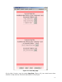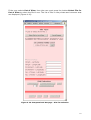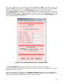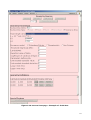
1
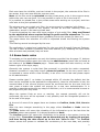
INGV - Istituto Nazionale di
Geofisica e Vulcanologia
DPC - Dipartimento della
Protezione Civile
Convenzione INGV-DPC 2004 – 2006
Progetto S2 - Realizzazione di un modello dinamico sperimentale di valutazione della
pericolosità sismica a scala nazionale
Project S2 - Development of a dynamical model for seismic hazard assessment at
national scale
CrisisWeb User Manual
By UR3 – INGV Milano-Pavia
Francesco Martinelli & Carlo Meletti
(ver. 1.2)
24th August 2009
Index
1
2
3
4
5
Introduction...............................................................................................1
1.1
Some basic rules ..................................................................................2
Registration and log-in ................................................................................4
Password...................................................................................................5
3.1
Reset Password ....................................................................................5
3.2
Change Password .................................................................................6
Main Console .............................................................................................7
4.1
Private Data File ...................................................................................8
4.1.1
Upload ..........................................................................................8
4.1.2
Remove ........................................................................................9
4.2
Project .............................................................................................. 10
4.2.1
New Project ................................................................................. 10
4.2.2
Abandon Project ........................................................................... 10
4.2.3
Save Project As….......................................................................... 10
4.2.4
Load Saved Project ....................................................................... 11
4.3
Project Elements ................................................................................ 12
4.3.1
Map Data .................................................................................... 12
4.3.2
Data of Computation Sites ............................................................. 14
4.3.3
Source Zone ................................................................................ 17
4.3.4
Add Source Zones Geometries form File........................................... 23
4.3.5
Data on Spectral Ordinates ............................................................ 23
4.3.6
Global Parameters ........................................................................ 24
4.3.7
Attenuation Models ....................................................................... 24
4.3.8
Assign Models to Sources............................................................... 27
4.3.9
Review of input data: Graphical Data............................................... 28
4.4
Running an elaboration ....................................................................... 29
4.4.1
Validate and Run .......................................................................... 29
4.4.2
Review of output data: Graphical Data............................................. 29
4.5
Submitted and Completed Solutions ...................................................... 32
Fatal Errors ............................................................................................. 34
i
Figures index
Figure
Figure
Figure
Figure
Figure
Figure
Figure
Figure
Figure
Figure
Figure
Figure
Figure
Figure
Figura
Figure
Figure
Figure
Figure
Figure
Figure
Figura
Figure
Figure
Figure
Figure
Figure
Figure
Figure
Figure
Figure
Figure
Figure
Figure
Figure
Figure
Figure
2.1: Login page - Initial page for user authentication ...................................4
3.1: Reset Password page - Step 1 ............................................................5
3.2: Reset Password page - Step 2 ............................................................5
3.3: Reset Password - Step 3....................................................................6
3.4: Change User Password page ..............................................................6
4.1:Main Console page. ...........................................................................7
4.2: File Upload page ..............................................................................9
4.3: Remove File page .............................................................................9
4.4: Project page .................................................................................. 10
4.5: Save As page................................................................................. 11
4.6: Load Project File page ..................................................................... 12
4.7: Data Map page .............................................................................. 13
4.8: Zoom on Main Console – Map Data ................................................... 14
4.9: Computational Set page .................................................................. 14
4.10: Computational Set page - Site list selection...................................... 15
4.11: Computational Set page - Example of error ...................................... 16
4.12: Computational Set page - Zoom on grid reduction............................. 17
4.13: Source Zone page - Initial screen shot............................................. 18
4.14: Source Zone page - Example of Fault Area ...................................... 19
4.15: Source Zone page - Adding a Smoothed Area ................................... 20
4.16: Source Zone page - Parameter for zone Smoothed & Non-Poissonian ... 21
4.17: SourceZone page - Zoom on Special Regions area............................. 22
4.18: Adding a special geometry source ................................................... 22
4.19: Spectral Ordinates page ................................................................ 23
4.20: Gloabal Parameter page ................................................................ 24
4.21: Attenuation Model page - selecting a template .................................. 25
4.22: Attenuation Model page - Abramson and Silva .................................. 26
4.23: Attenuation Model page - Attenuation table ...................................... 27
4.24: Assign Models page ...................................................................... 27
4.25: Review of input data ..................................................................... 28
4.26: Validation before elaboration.......................................................... 29
4.27: Graphical Data page ..................................................................... 30
4.28: Graphical Data page – Evaluation on a single point............................ 31
4.29: Graphical Data page - Textual report of the whole grid....................... 32
4.30: Main Console - Submitted and not Completed elabotations ................. 33
4.31: Main Console - Logs of jobs ended with and without errors ................. 33
5.1: Fatal Error page ............................................................................. 34
ii
1 Introduction
The application CrisisWeb is a web application to evaluate the seismic hazard.
It is designed to offer on the Web the functionality provided by the corresponding
desktop application Crisis 2008 and is built on the same classes (Crisis Core
Classes).
For the specific description of the application please refer to the Crisis 2008 User
Manual (to be released by UR1-Unam).
The differences between the two applications are driven mainly by the user interface,
while the functionality should be nearly the same.
The main difference is about the maps provided to the user while entering the input
data: the desktop application provides maps and graphs of the data in the same
window where the user is working; in the web application maps and some graphs can
be visualized in separate web page.
The web application offers to submit multiple elaborations at the same time, also for
the same user, and to delegate the workload to the server freeing the user PC from
heavy CPU load.
The application is designed to be used only by selected users. This requirement is
both technical and administrative.
The elaboration of data causes heavy CPU load for long times (hours or even days),
and it is executed in background while the user can be offline. The server can process
multiple elaborations simultaneously, and the associated cost is a longer time to
complete the elaborations.
If any web user could access the application there is a good chance the server would
be overloaded by useless elaborations.
Allowing the users to be offline while the server processes the elaboration, imply the
users can be recognised by the server to the next access, advised the elaboration is
finished and allowed to receive the results of their elaboration.
It is also a project requirement the application to be available only to identified users.
Therefore the users are granted by the application administrators.
Every set of input data is referred to a Project.
A project has a mapping with a DAT file, and can refer to additional data files, like
maps, attenuation tables, etc.
Users are expected to work on their own data, as well as on data files available to any
user of the application.
The data files available to all the users should be made available only when
considered stable, and not expected to be modified or removed. The rationale is that
changes to data files referred by a project could cause unexpected inconsistencies in
the results, possibly also not reported by the elaboration result.
If this situation were caused by private data file then the user is responsible; however
the user is not notified and cannot control changes to commonly available data files.
At the same time the users can modify their own data as part of their research work.
To accomplish this requirements each user is provided with a private area where to
upload (and remove) any private file, while one area is for the files available to all the
users.
Currently no one is granted the modification of the common area: the administrator
can access the common area working directly on the server.
1
Each user have the visibility, and can include in the project, the contents of the files in
two areas: their own area and the common area.
Note: all the files must be uploaded into the private area, or be in the common area,
before the user can use them. It is not possible to refer to file in the local PC.
It is possible to upload files in the private area while working on a project, and then
refer also to the just uploaded files.
The private area can contain only files; the area cannot be organised with folders.
The files the user upload to the system, as well as the files resulting from the
elaboration, are all in the same private area.
To avoid prompting the user with huge number of not useful files, they are filtered
by the application when required using file prefix and file extensions. The user
need to consider this constraint when uploading files to the system for later use.
The pages where the selection of a file is requested shows the filtering the system
apply.
This filtering cannot be changed by the user.
The application is tested and optimized for the use with Microsoft Internet Explorer.
The use of other browser is possible, but some features (e.g. disabling the input fields
after a button was pressed) may not work.
1.1 Some basic rules
To navigate on the application use only the buttons provided into the page. If buttons
are not sufficient please report the issue to the administrator (email can be found at
the bottom of the Main Console page – Please also report the web versions, on the
bottom-right of the login page).
Generally the system is quite fast (few seconds) to provide the action requested.
However sometime it may take longer: please be patient. In the very worst case it
is expected to return within a few minutes, or an error: in this last case please report
to the administrator.
Please consider that if no button is pressed within 15 minutes (by default, but the
time can be modified by the application configuration), then the connection is lost, the
unsaved data of the current project cannot be recovered and on the next time the
user press a button the system will prompt for a new user authentication. It is
possible to save the project at any stage of definition, so it is recommended to save to
the project file (DAT file) often.
When the system finds an error or warning, the request generally will not be
performed, the error will be reported in red, possibly near the recognised problem or
at the end of the page.
At the end of most of the pages there are buttons to Confirm, Undo, Exit, Save to
File.
After the user changes something in the page, either Confirm or Undo must be
selected.
The Undo button will cause the reloading of the information up to the last time the
Confirm button was pressed. It is always possible to Undo.
The Confirm button will cause the information to be saved in the system (not to the
project file!). Thereafter changes can be discarded only by leaving the project,
and thus having the data saved up to the last “Save to file”. The Confirm
button causes the system to validate the consistency of the new data, and possibly
2
returns an error message explaining the reason of any failure. If an error is returned
then the data was not saved.
The Exit button causes the return to the previous page. This button can be used only
when the data shown matches the data in the system, i.e. after either button Undo or
Confirm (with no errors) were pressed.
Finally the Save to File button save the data to the currently DAT file, and can be
pressed with the same rules explained for the Exit button. However this button will
cause an error also if either the project was not previously saved to a file, or if the file
was already processed (i.e. a file with same name and extension B1 exists). In case of
the failure a message is prompted to the user: in this case go back to the Main
Console and save the project with a different name, or remove the corresponding file
with extension B1 (note that removing the B1 file will cause to loose the
elaboration!).
It is not always feasible to enable only the correct buttons, therefore in some pages
the user will find all these buttons always enabled: if an inconsistent action is
requested (e.g. Exit instead of Confirm or Undo) then the system will report an
error in the page (in red).
To avoid the loss of input data when a project is under elaboration, or when the
elaboration was completed, it is not possible to save a file when a file with the same
name and the extension B1 already exists.
If the user wishes to override the solution that was submitted for
elaboration, the user should check the solution is not under elaboration (possibly
cancelling the elaboration) and then must cancel the file with extension B1 from the
private area (See “Remove Private Data File”).
Where it is possible to associate to the project a file with extension shp (shape file)
then the system expects all the associated (and required) files are in the same area
(private or common), otherwise it will rise an error.
For the rules about formats of the files to associate to the project please refer to the
Crisis 2008 manual.
Depending on the system where the web server is running, it is possible the decimal
separator is either comma ‘,’ or dot ’.’.
For the data entered in the web pages, the system try to recognise the character
used by the user as decimal separator. Where a change is required the system prompt
the user with an error-like message advising the system changed the format of the
number. If such a message is prompted the action which leaded to the message is not
performed and the user must require it again after checking the error-like message.
3
2 Registration and log-in
The use of the site is subject to registration.
The administrator will require the user to provide a private question and a private
answer to allow the user to self reset the password.
Normally the user will receive the password by email, with subject Password, and
containing a message like the following:
Please return to the site and log in using the following
information.
User Name: UserName
Password: Ev0Q(=9hj@cR(i
The user accesses the site using the assigned “User name” and “Password” to enter in
the Login page (Figure 2.).
Note: the user name and password are case sensitive.
Figure 2.1: Login page - Initial page for user authentication
Known issues: it may happen the correct user name and password are provided, but
the application returns to the login page. In this case enter the user name and
password again.
The problem is caused by the session not being activated at the first attempt, because
of the page not coming from the server but by the cache.
4
3 Password
3.1 Reset Password
If the user forgets the password, it can be reset by following the link Forgotten
Password in the Login page (Figure 2.) to access the Reset Password page. Here
the user can always break the process pressing the Start Session button, and going
back to the Login page, or proceed using the Submit button.
The user will be requested to provide the user name (Figure 3.1):
Figure 3.1: Reset Password page - Step 1
and answer the private question provided at subscription time (Figure 3.2):
Figure 3.2: Reset Password page - Step 2
If there process complete successfully the page showed in Figure 3.3 is displayed, and
an email, with subject Password, will be received.
5
Figure 3.3: Reset Password - Step 3
It is recommended the user change the password after a reset password.
Note: the password is known only by the system and automatically sent to the user.
Note: the answer to the private question is registered during the process of creating
the user. If the user loose the private answer the account must be recreated by the
administrator (however the files in the private folder are not lost!).
3.2 Change Password
The user has no limit for to change the password.
Following the link To Change Password in the Main Console page (Figure 4.1) the
user access to the Change User Password page (Figure 3.4) where the user is
requested the current password, and to type twice the new password.
Figure 3.4: Change User Password page
Restrictions may apply to the new password, e.g. minimum number of characters and
or digits. In case these restrictions are in place the user will be prompted if the new
password does not comply.
On successful change password the user will be sent an email with subject Confirm
of change password.
6
4 Main Console
Once the user log-in, the user is prompted with the Main Console (Figure 4.1).
Figure 4.1:Main Console page.
7
Here there are the following features:
1) User Info – on top the user has a feed-back of the User Name used to log-in (in
the example “Martinelli”) and the link To Change Password where the user can self
change the password.
2) Jobs – there is a section for the logs resulting from Submitted and completed
elaborations, (in Figure 4.1 the same project – 11_06_2009 2 – reported an error,
and then was elaborated three times) and a list of submitted jobs not jet completed
where to check the time the job is running (in minutes), the expected time to finish
(in minutes), and a button to abort the elaboration (in Figure 4.1 the project
11_06_2009 2 is in elaboration).
3) Project – in the section, if a project is open, there are information on the current
title of the project, and the associated file name. Here are also the buttons to create
(New), abandon, load, save the project.
4) Files – all the files used by the project must be uploaded on the server using the
Upload Private Data File. Also the button to remove files in the private area is present.
5) Input elements – all the element of the project are assigned from this section.
6) Maps – maps of the model and (after the elaboration is completed) of the results
are available from here.
7) Run – this is the section where to submit a project for the elaboration, and check
some results.
To create a project the user needs to provide several information elements.
Information are grouped and the user access each type by a different button on the
Main Console.
It is required a project is opened (either by creating it, or loading one previously
saved) to enable the buttons in Input elements section.
When data on the open project are not saved to a file, buttons to load a new project
(New Project and Load Saved Project) are not enabled: this is to avoid the user
loose the information provided by mistake.
To Validate and Run the elaboration on a project, the project has to be saved, and
no elaboration on the project can be present: the system assumes the elaboration is
present if exists a file with the same name as the DAT file and extension B1.
When the elaboration of a project is completed the button Textual Results is
enabled, and the button Show Graphical Data shows also the graphical results.
4.1 Private Data File
4.1.1 Upload
The users can upload to their private area any file they may need. There is no
restriction on the name or extension.
It is not possible to overwrite an existing file. If a file need to be overwritten ,
then it is required to Remove it, and then Upload.
The system is configured to allow the uploading of big files, but this value cannot be
set to infinite.
Please note that the system cannot report to the user if the file is too big: if the file is
not loaded, and no error is reported, then it is very likely the system was not
configured for uploading such a big file. Please contact the administrator to properly
increase the limit.
8
To upload the file select Upload Private Data File from the Main Console: the
Upload File page is presented (Figure 4.2).
Next to the text box select Browse… (spelling depends on the browser, in Figure 4.2
“Sfoglia…”) and select the file on the user PC. Finally press Load File.
If no error is displayed, then the operation was successful.
Figure 4.2: File Upload page
Currently it is not possible to upload multiple files at once.
4.1.2 Remove
The user can remove any file from its private area.
From the Main Console, pressing Remove Private Data File, the user is prompted
the Remove File page (Figure 4.3) with the list of the files actually present in the
private area. Next to each file a button Remove let the file to be removed.
Figure 4.3: Remove File page
9
4.2 Project
After a project is loaded it is possible to Save and Abandon the project, as well as to
access and change the project elements.
On the Main Console page, section Project, the system advices whether a Crisis
instance is open, the DAT file is associated to it (if any), and allow the user to provide
a title.
The title is not associated to the file name, and it is there to help the user to identify
the currently loaded project.
4.2.1 New Project
After the user select New Project, a new clean project is loaded into the system, but
the data is not saved to any file: it is only in memory.
It is possible to select New Project only if no project is opened, or if the project in
memory was saved to a file and there were no changes thereafter.
4.2.2 Abandon Project
Requiring this action make the system to discard all the information on the current
project not saved to a file.
To avoid the user requires this action by mistake, a special confirmation is required in
the Abandon Project page (Figure 4.4).
Figure 4.4: Project page
4.2.3 Save Project As…
This action will show the SaveAs page (Figure 4.5) with the list of all the projects
currently saved by the user.
All project file have extension DAT, in upper case.
The system saves projects with the correct extension, but the users need to consider
the extension in case they upload the project (DAT) file via the File Upload page
(Figure 4.2).
Note: uploading a DAT file DOES NOT load the project, it just copies the file from
the user PC into the private area, as the uploading of any other file type.
On successful, the user is returned to the Main console.
10
Figure 4.5: Save As page
From the Save As page the user can:
•
Save to current File
This button is enabled only if the project was previously saved, or if it was loaded
from one previously saved.
After the request the project information are saved to the currently used file displayed
on the right of the button.
•
Replace
All the project files have this button on the right. The information of the current
project will override those in the selected file.
This action will cause an error in case the user requires to Replace the currently used
file.
•
Save As…
The user must type a name in the box near the button.
If the file is already present an error is reported.
If the user wants to use a previously used file name, then it is a replacement, and
the proper request button (Replace) must be used.
4.2.4 Load Saved Project
The button is enabled only if the current project was not modified since it was last
saved to a file. The Load Project File page (Figure 4.6) contains s list of the private
files with extension DAT is provided, with next to each file the button Load.
11
Figure 4.6: Load Project File page
The system read the project file, and checks if all the referenced files are present, and
report the files not found and other errors, if any.
After the successful loading of the file, the current project is the one present in the
selected file, and the user is presented the updated Main Console page.
Note: if the user wishes to upload a project file, then it is required all the referenced
to files are relative to the current directory (the private directory), and no references
are allowed to the common files.
Note: in this page there is no option for project files in the common area: the reason
is that currently it is not possible to make project files available from the common
area.
4.3 Project Elements
In this section of the Main Console page are present all the elements used by a
Crisis project and here are described the functionality to handle them.
The buttons are enabled only when a project instance is open.
4.3.1 Map Data
The Map Data page (Figure 4.7) shows the Map and City files present in the private
and common area.
The files must be prefixed with map for map files, and city for city files, and both can
have extension shp (shape) or asc (ASCII).
12
Figure 4.7: Data Map page
On the Main Console, near the button Map Data (Figure 4.8), two check boxes show
whether a map and city files were associated to the project.
13
Figure 4.8: Zoom on Main Console – Map Data
4.3.2 Data of Computation Sites
The Computational Set page (Figure 4.9) allows the user to input the sites where to
perform the elaboration.
The user can select either a file of sites or the grid of sites. Both selection allow to
define additional areas for the grid reduction.
Figure 4.9: Computational Set page
14
If the user selects List of Sites, then the user must press the button Select File for
List of Sites to select the file to use. The list of files in the private and common area
are displayed (Figura 4.10).
Figura 4.10: Computational Set page - Site list selection
15
The files containing list of sites must be prefixed by sites and have either the
extension shp (for shape file) or asc (for ASCII file). Only after the user has selected
the file and pressed Confirm, the Grid Reduction area will become enabled.
If the Grid of Sites is selected, all the parameters must be provided. In this case the
Grid Reduction area is always enabled; however if any grid parameter value was
changed, then Confirm or Undo button must be pressed before Add Polygon or an
error is displayed as in Figure 4.11.
Figure 4.11: Computational Set page - Example of error
The Grid Reduction area allow the user to handle the reduction polygons.
Pressing the Add Polygon button appears the grid to insert the polygon with a basic
default grid (Figure 4.12).
The polygon index (on the left of the Remove Polygon button) is set automatically.
When grid reduction polygons are defined for the computational set, selecting the
index prompts the associated set of points for the polygon.
16
Figure 4.12: Computational Set page - Zoom on grid reduction
On pressing the Submit & Confirm button of the Grid Reduction area a consistency
check is performed on the polygon (e.g. if two points overlap) and if an error is found
a proper message is displayed.
Please note: in the Grid Reduction section of the page the Remove Polygon button
is enabled only after the polygon was submitted; beforehand the user can select the
Undo button.
4.3.3 Source Zone
The Source Zone page allows the user to handle the source zones, their geometries
and parameters, the occurrence model and the associated parameters.
The initial screen shot is showed in Figure 4.13, from where the user can add a new
source type, or select a geometry source previously entered from the drop down
nearby the Remove Source Zone button.
It is not possible to change the type of one source zone (area, fault, point or
smoothed – refer to the Crisis 2008 User Manual for the definition) once it was
selected.
17
Figure 4.13: Source Zone page - Initial screen shot
Depending on the source type some coefficients must be provided: coefficients K1 and
K2 for area type, and K3 and K4 for fault type. These coefficients can be provided by
the user (select custom values in the drop down box – see Figure 4.14) or selected
from one of the predefined set.
In the Web Application it is possible to add a set of coefficient values only at server
level, i.e. for all the users, and only the administrator can do this task.
In Figure 4.14 is an example of adding a Fault Area. By default the minimum number
of geometric points are added to the source (see Geometry Definition area in the
page) with default values: three points for area type, two points for fault types, one
point for point type.
18
Figure 4.14: Source Zone page - Example of Fault Area
19
For smoothed area the user is prompted to select an SSG file, whose format is defined
into the Crisis 2008 User Manual. The file must be prefixed with source and have the
extension ssg (Figure 4.15).
Figure 4.15: Source Zone page - Adding a Smoothed Area
Where the selected occurrence model is Non-Poisson, then the expected seismicity
parameter is an NPS file the user must load using the button Load Parameter File
(Figure 4.16).
The file to load must be prefixed with source and have the extension nps (NonPoisson file).
20
Figure 4.16: Source Zone page - Parameter for zone Smoothed & Non-Poissonian
4.3.3.1
Special Source Zone Data
To each source zone can be applied Special Regions, that is a geographic region
where it is possible to adopt a different Ground Motion Predictive Equation (GMPE)
with respect to the model for that seismic source zone.
Special Regions are handled in the Special Regions area at the bottom the Source
Zone page (Figura 4.17).
21
Figura 4.17: SourceZone page - Zoom on Special Regions area
The user can add the special regions either adding all the regions defined in a shape
file, using the button Add Special Regions from File. All the regions in the selected
shape file will be added to the currently defined special regions for the source.
The file must be prefixed with reg and have the extension shp (shape file).
Figure 4.18: Adding a special geometry source
22
To Modify or Remove a special region it must be selected from the drop down list
between the two buttons.
The user can also add a single special region pressing the button Add Special
Region.
In this case a new page is displayed where the user can add the single geometry
points defining the geometry, or load the geometry data from a shape file (the first
geometry from the file will be loaded) as showed in Figure 4.18.
It is a good practice (even if not mandatory) to assign each special region a different
name, which will be showed in the drop down box of the Special Regions area for
modification.
It is also possible to load the data into the table from a shape file using the button
Replace Special Region from File. The file must be prefixed with reg and have the
extension shp.
4.3.4 Add Source Zones Geometries form File
It is also possible to add to the project all the source zones defined in a shape file.
Using this option it is possible to add zones of type area, fault and points.
The geometries found in the shape file will be added to the currently defined source
zones.
From the Main Console the user press the button Add Source Zones Geometries
from File, and the list of files prefixed by source and with extension shp are
prompted to the user for the selection.
4.3.5 Data on Spectral Ordinates
In the Spectral Ordinates page (Figure 4.19) it is possible to define the intensity
levels and structural periods to use during the elaboration.
At least one structural period is required.
Figure 4.19: Spectral Ordinates page
23
4.3.6 Global Parameters
The Global Parameter page is used to define the parameters showed in Figure 4.20.
Please note that the time frame matching for the attenuation model is NOT performed
in this page, but from the Main Console, when the user request Validate and Run.
Figure 4.20: Gloabal Parameter page
4.3.7 Attenuation Models
The Attenuation Model page allows to define the GMPE which will be used by the
elaboration, and their parameters.
The application contains a number of reference model templates.
To use a model the user needs to add a model to the project.
A model is a reference model template, with specific parameters defined by the user,
the available parameters depending by the reference model template.
The first step to add an attenuation model is using Add Attenuation Mod. button.
Next, the user can select between the available attenuation model templates next to
the button (Figure 4.21).
24
Figure 4.21: Attenuation Model page - selecting a template
For the meaning and description of each template refer to the Crisis 2008 manual.
In the Web Application it is possible to add a template only at server level, i.e. for all
the users, and only the administrator can do this task.
Depending on the selected template the user will need to add some information for
the associated parameters:
• selections of values (like in Figure 4.21, for Youngs97 for Soil type parameter,
to be either Soil or Rock);
• filling of data, and check box selection (like in Figure 4.22, for
AbramsonAndSilva97 for Units coefficient and Site is in the hanging wall
parameters);
• select file (like in Figure 4.23, for Attenuation Table for Attenuation Table
parameter).
Number and types of parameters, labels for selections and check boxes, allowed
values, and file extensions are defined by the template developer: refer to Crisis
2008 manual.
25
Figure 4.22: Attenuation Model page - Abramson and Silva
Once the user successfully press the button Confirm it is not possible to change the
model template, but only the user name of the model, and the parameter values.
26
Figure 4.23: Attenuation Model page - Attenuation table
4.3.8 Assign Models to Sources
Each source zone must be assigned to one of the attenuation models defined in the
Attenuation Model page.
Figure 4.24: Assign Models page
Where special regions are defined for a source zone, each special region must be
assigned to an attenuation model as well.
The Assign Models page (Figure 4.24) allows the assignment.
27
If not all the zones were assigned to an attenuation model, pressing the Confirm
button will cause a warning to be displayed, but the data is recorded to the system,
and it is possible to press Exit and Save to File buttons.
The above behaviour is different from the other pages, however it is appropriate and
consistent with the behaviour of the desktop application.
4.3.9 Review of input data: Graphical Data
Before running the elaboration, at any stage while defining the data, it is possible to
view the map of the data defined using the button Show Graphs and Graphical
Data from the Main Console.
The user can decide to view one or multiple elements of the data: cities, map,
sources, computational grid (Figure 4.25).
Additionally the user can navigate the map with zoom and pan operations selecting
the proper radio button and then clicking the map where it will be centred.
Figure 4.25: Review of input data
28
4.4 Running an elaboration
4.4.1 Validate and Run
It is possible to access the Validate and Run page () only if all the following
conditions exists:
• the project was saved to a file;
• there were no changes to the project since it was saved;
• the elaboration was not already requested.
The page shows the possible missing or inconsistent data the application found in the
project.
Only if no problem is reported the button Run and Exit is enabled.
Figure 4.26: Validation before elaboration
Once the Run and Exit button is pressed the user return to the Main Console, and
the project is closed, so that the user cannot change the input data.
In this situation, if the user want to open the project, it will not be possible to save it
with the same name, avoiding to loose the input data.
4.4.2 Review of output data: Graphical Data
Once the elaboration is finished it is possible to browse the results loading the project
and using the button Show Maps and Graphical Data.
In the Graphical Data page (Figure 4.27) it is possible to view the input data (using
the View Model Only button) as well as the results of the elaboration.
29
Figure 4.27: Graphical Data page
On the graph it is possible to perform zoom and pan action on the image, select if
auto scale or user defined limits should apply to the range of colour.
If Evaluate on Point is selected, clicking with the mouse on the map shows the
evaluation on a single point in graphical forma and (if the check box Show textual
report is selected) as text on a table (Figure 4.28).
30
Figure 4.28: Graphical Data page – Evaluation on a single point
If the list of cities was part of the input data, then it is also possible to select one of
the cities and directly require its evaluation.
It is also possible to get the output associated to all the evaluated points in tabular
format by pressing the button Textual Report on Grid. This will show a table below
the map, with the coordinates and evaluation for each point ().
31
Figure 4.29: Graphical Data page - Textual report of the whole grid
4.5 Submitted and Completed Solutions
After the user requires the run of a project, on top of the Main Console will appear
the list of the project files submitted and not yet completed (Figure 4.30).
Please note: it may take a few minutes before the new elaboration appears in the list.
If, for any reason, the user want to stop the run it is possible by pressing the Cancel
button near to the project file name.
Note that in this case the elaboration created the file B1, and the application will not
allow the user to call for running the project again (button Validate and Run
disabled) when the project is loaded.
To enable the application to run the project the user must delete the B1 file (using
Remove Private Data File button) and then load the project.
32
Figure 4.30: Main Console - Submitted and not Completed elabotations
When a run completes, log information are saved and prompted to the user on top of
the Main Console (Figure 4.31). The log provide information on the number of
minutes required to complete the run.
If the run is aborted, then a value of -1 is reported.
Any error reported during the run is visible in the log.
The user can clear this information (all together) by pressing the Clear Logs button.
Figure 4.31: Main Console - Logs of jobs ended with and without errors
33
5 Fatal Errors
The application try to prevent possible user errors and where possible early warning
and errors are returned to the user as soon as identified.
However it is possible some severe problem happen, either because of unexpected
user input or because of an application error.
Still, in this case the application will return a special page, shown in Figure 5.1.
Figure 5.1: Fatal Error page
Then the user is redirected to a page, from where it is possible to return to the Main
Console or logoff.
If the user had a project opened, the project in memory (not yet saved to a file) may
have inconsistent data. If the user wants to try saving the data in memory we
recommend to return to the Main Console only for saving the current project using a
different file name.
In any case the user should logoff as soon as possible.
34