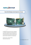
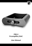
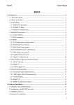
1
l
a
u
n
a
M
s
’
r
Use
[
MSD/PT0600C-5.1
MSD/PT0600C-III
MSD/PT0200C
MASTER STEREO DISPLAY
Technical Reference Manual
interstage
Phistersvej 31, 2900 Hellerup, Danmark
Telefon 3946 0000, fax 3946 0040
www.interstage.dk
- pro audio with a smile
www.dk-audio.com
]
MSD/PT0600/200 - Technical Reference Manual
Copyright©2002 DK-Audio A/S, Herlev, Denmark.
All rights reserved.
No part of this publication may be reproduced or distributed in any form, or by
any means, without prior written consent from DK-Audio A/S.
Trademarks
Analog Devices is a registered trademark of Analog Devices, Inc., USA
Crystal is a registered trademark of Cirrus Logic, Inc., USA
AKM is a registered trademark of Asahi Kasei Microsystems Co., Ltd., Japan
Tektronix is a registered trademark of Tektronix Inc., USA
DK-Scale is a registered trademark of DK-Audio, Denmark
JellyFish™ is a registered trademark of DK-Audio, Denmark
MSD/PT0600/200 - Technical Reference Manual
Contents
Section . . . . . . . . . . . . . . . . . . . . . . . . . . . . .Page
Section . . . . . . . . . . . . . . . . . . . . . . . . . . . . .Page
1.
1.1
Introduction . . . . . . . . . . . . . . . . . . . . . . 1
This Manual . . . . . . . . . . . . . . . . . . . . . . 1
5.
Mounting . . . . . . . . . . . . . . . . . . . . . . . . 9
6.
Audio Connections - Breakout Cable . 11
2.
The Audio Matrix . . . . . . . . . . . . . . . . . 2
7.
Precautions . . . . . . . . . . . . . . . . . . . . . 12
3.
External Synchronisation and the
Sample Rate Converter . . . . . . . . . . . . 3
8.
Presets . . . . . . . . . . . . . . . . . . . . . . . . . 13
9.
The “DK-SCALE” PC-Software
Program . . . . . . . . . . . . . . . . . . . . . . . . 15
4.
4.1
4.2
4.3
4.4
4.5
4.6
4.7
4.8
4.9
4.10
Hardware . . . . . . . . . . . . . . . . . . . . .
Analogue Audio Inputs . . . . . . . . . . . .
Digital Audio Inputs . . . . . . . . . . . . . .
Analogue Audio Output . . . . . . . . . . .
Digital Audio Output . . . . . . . . . . . . .
External Sync Source Input . . . . . . . . .
DSP Microcomputer . . . . . . . . . . . . .
Flash-PROM (Program Storage Media)
LCD Display . . . . . . . . . . . . . . . . . . . .
Hardware ID . . . . . . . . . . . . . . . . . . . .
Power Supply . . . . . . . . . . . . . . . . . . .
.
.
.
.
.
.
.
.
.
.
.
.
.
.
.
.
.
.
.
.
.
.
5
5
5
5
6
6
6
7
7
7
8
10. Software Upgrade . . . . . . . . . . . . . . . . 17
10.1 COM Port Selection . . . . . . . . . . . . . . . . 17
10.2 Update Procedure . . . . . . . . . . . . . . . . . 17
11.
Appendix A: Specifications . . . . . . . . . 18
12.
Appendix B. Mechanical Dimensions . 22
MSD/PT0600/200 - Technical Reference Manual
Contents
Section . . . . . . . . . . . . . . . . . . . . . . . . . . . . .Page
Section . . . . . . . . . . . . . . . . . . . . . . . . . . . . .Page
13. Appendix C. Pin Configuration . . . . . . 25
13.1 Appendix C-1. Pin configuration for
VGA and Utility DSUB Connector . . . . . . 25
13.2 Appendix C-2. Pin configuration for
Analogue and Digital AES-3 Input/
Output DSUB connector . . . . . . . . . . . . 26
15.
15.1
15.2
15.3
14.
14.1
14.2
14.3
14.4
14.5
Appendix D.
Factory Presets for MSD/PT0200C
Appendix D-1.
Factory Preset 0: BASE SETUP . . . .
Appendix D-2.
Factory Preset 1: ANALOGUE . . . . .
Appendix D-3.
Factory Preset 2: DIGITAL . . . . . . . .
Appendix D-4.
Factory Preset 3: ANALOGUE+MS .
Appendix D-5.
Factory Preset 4: DIGITAL+MS . . . . .
. . . 28
15.4
. . . 28
15.5
Appendix E.
Factory Presets for MSD/PT0600C-III
Appendix E-1.
Factory Preset 0: BASE SETUP . . . . . .
Appendix E-2.
Factory Preset 1: ANALOGUE . . . . . . .
Appendix E-3.
Factory Preset 2: DIGITAL . . . . . . . . . .
Appendix E-4.
Factory Preset 3: ANALOGUE+MS . . .
Appendix E-5.
Factory Preset 4: DIGITAL+MS . . . . . .
. 38
. 38
. 40
. 42
. 44
. 46
. . . 30
16.
. . . 32
. . . 34
. . . 36
Appendix F.
Factory Presets for MSD/PT0600C-5.1
16.1 Appendix F-1.
Factory Preset 0: BASE SETUP . . . . . . . 48
16.2 Appendix F-2.
Factory Preset 1: LCR . . . . . . . . . . . . . . 50
16.3 Appendix F-3.
Factory Preset 2: LRC . . . . . . . . . . . . . . 52
MSD/PT0600/200 - Technical Reference Manual
Contents
Section . . . . . . . . . . . . . . . . . . . . . . . . . . . . .Page
Section . . . . . . . . . . . . . . . . . . . . . . . . . . . . .Page
16.4 Appendix F-4.
Factory Preset 3: DIGITAL 1+2 . . . . . . . . 54
16.5 Appendix F-5.
Factory Preset 4: DIGITAL 3+4 . . . . . . . 56
16.6 Appendix F-6.
Factory Preset 5: DIGITAL 5+6 . . . . . . . 58
18.2 Appendix H-2.
MSD/PT0600C-III . . . . . . . . . . . . . . . . . . 65
18.3 Appendix H-3.
MSD/PT0600C-5.1 . . . . . . . . . . . . . . . . . 66
17.
Appendix G.
Audio Matrix Flow Charts
17.1 Appendix G-1.
MSD/PT0200C . . . . . . . . . .
17.2 Appendix G-2.
MSD/PT0600C-III . . . . . . . .
17.3 Appendix G-3.
MSD/PT0600C-5.1 . . . . . . .
18.
. . . . . . . . . . 60
. . . . . . . . . . 60
. . . . . . . . . . 61
. . . . . . . . . . 62
Appendix H.
Sync Clock Flow Charts . . . . . . . . . . . 64
18.1 Appendix H-1.
MSD/PT0200C . . . . . . . . . . . . . . . . . . . . 64
19.
Registration Card . . . . . . . . . . . . . . . . 69
MSD/PT0600/200 - Technical Reference Manual
MSD/PT0600/200 - Technical Reference Manual
1
1. Introduction
Congratulations! By purchasing a Master Stereo
Display (MSD) from DK-Audio you have decided to
actually "See What You Hear”. We are certain that
your Master Stereo Display will prove an invaluable
tool in your daily work.
If you have any suggestions or points of view for
future functions or options, we welcome your comments. Please write to DK-Audio at the address on
the rear page of this manual, or call
+45 44 85 02 55. You can also use the enclosed
Registration Card to send us your remarks and
observations. Your Registration Card is also the
easiest way for you to receive up-to-date information from DK-Audio on future Master Stereo Display
products. Please also check our website at
www.dk-audio.com!
1.1 This Manual
This manual is an addendum to the Software
User’s Manual covering all aspects of the MSD
Operating System. In this manual all model specific
information can be found. This includes mechanical
dimensions, electrical specifications, hardware
descriptions, mounting descriptions, flow-charts,
factory presets and pin-out descriptions.
•
For any question regarding the operation of the
MSD unit, please refer to the Software User’s
Manual
At time of press (2002) this manual covers the
following MSD models:
MSD600C-III, MSD600C-5.1, MSD200C,
PT0600C-III, PT0600C-5.1 and the PT0200C.
All through this manual any of the supported
models will be referred to simply as the MSD.
2
MSD/PT0600/200 - Technical Reference Manual
2. The Audio Matrix
The Audio Matrix function of the MSD has become
the very heart of the unit. Almost all parameter settings originate from the Matrix.
The different supported MSD models are
configured as follow:
MSD-Series
MSD200C
PT0200C
The MSD features a full 32 x 16 Audio Matrix.
Depending on the configuration of the actual MSD
model the available Inputs and Outputs can be
assigned from the Audio Matrix Menu.
Any input channel may be routed to any output,
including separate Left/Right channels of an AES-3
stream. Any function on the MSD is treated as an
Output and is assigned an input from the Audio
Matrix just like any other physical Output source.
There are therefore no restrictions to the routing of
a signal.
Interface:
Analogue Stereo
Inputs
Analogue Stereo
Outputs
Digital AES-3
Inputs
Digital AES-3
Outputs
•
MSD600C-III
PT0600C-III
MSD600C-5.1
PT0600C-5.1
1
1
-
1
1
-
1
2
3
1
2
-
Please refer to section 17 for a complete set of
Audio Matrix flowcharts for all supported
models
MSD/PT0600/200 - Technical Reference Manual
3
3. External
Synchronisation and
the Sample Rate
Converter (SRC)
The MSD has been designed to run on a fixed
internal sample rate at 48 kHz. However the user
can force the MSD to synchronise to any of the
available AES-3 Inputs.
•
Please refer to section 18 for a complete set of
Synchronisation flowcharts for all supported
models
Since the unit’s internal sample rate also determines the AES output sample rate you can use the
external sync feature to synchronise the AES outputs sample rate. For details on how to set up the
MSD for external synchronisation please see section 8.2.4.1 “SRC Bypass and external sync” in the
software manual. It is normal that professional
audio equipment such as mixing consoles are fitted
with sample rate converters in their AES input
stage. In these cases it is not necessary to synchronise the AES output signal.
When an external sync source has been selected,
the MSD will sync to this input whether a valid sync
signal is present or not. If no valid signal is detected an error warning will be displayed on the MSD.
Even though the MSD is able to lock up to AES-3
signals at 96 kHz, an external AES-3 sync signal
with a sampling rate higher than 48 kHz should not
be used, as it may cause glitches in the audio
stream.
Synchronising to a lower sample rate than 48 kHz
(like 44.1 kHz) will not be a problem. It is however
4
MSD/PT0600/200 - Technical Reference Manual
not recommended to sync to an external sync
source lower than 44.1 kHz since this will effect the
ballistics of the MSD’s meter functions.
When using the MSD with one of the DMU scales
(which are true peak scales) it is recommended that
the MSD SRC’s used are in Bypass mode. The rea-
son is that the SRC under certain situations effects
the peak value of the input signal.
In all other PPM Scales where the displayed level is
based on the energy of the signal and not the true
peak value, the SRC will not effect any measurements.
MSD/PT0600/200 - Technical Reference Manual
5
4. Hardware
The MSD has been designed with the very best
technology available today ensuring superb performance, high flexibility and an outstanding audio
performance.
4.1 Analogue Audio Inputs
The Analogue Input is designed around a 24-bit
Analogue-to-Digital converter (ADC) AKM®. This
converter, the AK5383, is using AKM’s high performing dual bit S/D conversion type to obtain a
dynamic range close to 110 dB. Combined with a
transformer-balanced input stage it forms a very
high performance Input stage. The analogue input
on all supported MSD models is able to handle
+24 dBm input signal.
4.2 Digital Audio Inputs
All supported MSD models are using the same
Digital Audio Input circuit designed around the
Cirrus Logic® AES-3 receiver chip, the CS8420.
This AES-3 receiver has not only become an industry standard but also contains the Sample Rate
Converter (SRC) used by the MSD. The SRC
ensures correct synchronisation of all AES-3 input
sources, making it possible to source to several
asynchronous AES-3 streams simultaneous.
The CS8420 is able to lock on any sample rate
between 32 kHz to 96 kHz and convert it to the
used internal sample rate of 48 kHz (when no
external sync source is used).
The Input stage to the AES receiver is transformerbalanced according to the AES specifications. This
AES-3 Input stage will generally also interface to
the consumer S/P Dif format when grounding one
of the balanced AES-3 input terminals. However,
since the signal level (eye-pattern) of a S/P Dif is
not compatible with the AES-3 specifications, there
is no guarantee for an error free reception.
6
MSD/PT0600/200 - Technical Reference Manual
4.3 Analogue Audio Output
4.5 External Sync Source Input
The Analogue Output are designed around the
AK4324 24-bit Digital-to-Analogue converter (DAC)
from AKM®. This converter of the S/D type,
ensures an amazing dynamic range of 115 dB. The
analogue outputs are electrically balanced and are
able to output a +18 dBm signal level.
All supported MSD models are able to use any of
the available AES-3 inputs as an External AES-3
Sync Input. This is a huge advance since no dedicated Sync inputs are required.
The MSD can be set to synchronise to an AES-3
signal in the range 32 kHz to 50 kHz.
4.4 Digital Audio Output
4.6 DSP Microcomputer
The Digital AES-3 Output is a true transformerbalanced output specified by AES. The actual AES
encoding is done by the Cirrus Logic® AES-3
transceiver chip, the CS8420.
The AES-3 outputs will always be synchronous to
the used master clock, which either can be driven
from the external sync input or from the internal
48 kHz clock oscillator.
Combined with the SRC on the AES-3 input this
arrangement enables the MSD’s to be used as a
high performance SRC taking an AES-3 input signal of any arbitrary sample rate between 32 kHz to
96 kHz and convert it to the internal used sample
rate.
The MSD data processing is entirely based on a
very powerful Digital Signal Processing (DSP) chip,
a so called DSP (Digital Signal Processor) Micro
computer. By using DSP all errors with ballistic and
scaling found on older analogue VU-Meter based
equipment is virtually eliminated.
The Software Version referred to in the Info Menu is
the software running on this DSP Microcomputer.
The used DSP is a 52 MIPS version of the
Analogue Devices® ADSP-2183, a single-chip
microcomputer, optimised for digital signal
processing (DSP), and other high-speed numeric
processing applications. The computer has
MSD/PT0600/200 - Technical Reference Manual
16 K-words of (16-bit) data memory RAM, and
16 K-words of (24-bit) program memory RAM,
on-chip.
4.7 Flash-PROM (Program Storage
Media)
using a Display Driver design developed by
DK-Audio.
There are several suppliers of TFT VGA displays
with a very high variation in quality. DK-Audio is
only using the very best TFT technology available
today. These are a bit more expensive than commonly used LCD displays but so much better.
Remember: “You See What You Hear”!
All programs executed by the DSP Microcomputer
are stored in a FLASH-PROM integrated circuit.
The flash-prom configuration allows new software
versions to be downloaded via the RS232 serial
communication port.
4.8 LCD Display
The MSD600M is fitted with the very best in LCD
display technology: A high-quality, 640 (horizontal)
x 480 (vertical) pixel, full-colour TFT LCD display
with extra high contrast and viewing angle. The display has a dual tube cold cathode (CCFT) installed
inside the unit for background illumination with an
expected lifetime of approximately 50,000 hours.
The display is controlled directly from the DSP
NOTE:
LCD pixels turn black or radiate different
colours.
The LCD is constructed with precision technology so 99.99% of the pixels are active, but of the
remaining 0.01%, there are pixels that may be
black or emit light constantly in a fixed colour.
This phenomenon is not a malfunction and are
therefore not covered by the 2-year factory
warranty
7
8
MSD/PT0600/200 - Technical Reference Manual
4.9 Hardware ID
4.10 Power Supply
All Newer models of the MSD product family have
been designed around a single common operation
system (OS). To enable this OS to detect which
MSD model it is running on, each MSD is equipped
with a unique Hardware ID code.
All supported MSD models are using an external
power supply of the desktop type. This enables the
MSD itself to be more compact for easy instalment.
The power supply is based on the switch-mode
principle. Power input is through the 9-pin DSUB
Utility connector found at the rear of the unit.
This number can be found in the Info Menu of the
MSD.
MSD versions covered in this technical manual
have been assigned the following hardware ID
codes:
MSD Model:
ID Code:
MSD200C/PT0200C
MSD600C-III/PT0600C-III
MSD600C-5.1/PT0600C-5.1
MSD600M
*) not covered by this manual
0242
0263
0253
0100*)
Under normal conditions the user should not be
concerned about the function of this ID.
•
Recommended supply voltage range is
12-24V DC 24W
NOTE: High Voltage! Special care must be taken
in a service or maintenance situation, as 600V
AC is present on the PCB.
MSD/PT0600/200 - Technical Reference Manual
9
5. Mounting
The supported MSD models are divided into two
groups. The PT versions (PT0200C, PT0600C-III
and PT0600C-5.1) designed for 19” rack mounting
and the free standing MSD models.
The PT versions are all equipped with four brass
springs mounted on the back of the unit. These
springs will fix the MSD in the 19” mounting rack
with enough force to ensure a permanent installation. The MSD has been engineered to fit in both a
Philips and a Tektronix 19” Instrument rack.
DK-Audio offers a 19” instrument rack extension
bracket that extends the depth of the MSD to
match CRT based equipment normal used together
with the MSD. This extension can also be configured to work as the breakout cable for the MSD as
well as a holder for the desktop power supply.
Please visit our homepage at www.dk-audio.com
for more information regarding this extension
bracket.
The remaining three MSD models are designed to
fit into the supplied free standing mounting bracket, making it easy to mount the unit on top of any
console or desk. The bracket makes it possible to
adjust the unit both horizontally and vertically for
the best viewing position. To mount the MSD in as
flexible a manner as possible, always use the supplied base-plate supplied with the mounting bracket.
When purchasing a model MSD200C, MSD600C-III
or MSD600C-5.1 enclosed fittings for mounting
are:
1 x bracket (U-form), 1 x circular base-plate, 3 x
finger screws with star-washers. Desk or console
mounting screws are not supplied, contact your
desk or console manufacturer if in any doubt as to
mounting procedure.
For best viewing angle horizontal and vertical positioning please follow these mounting guidelines:
Screw the base-plate to your console or work surface using two 4 mm wood screws (or an appropri-
10
MSD/PT0600/200 - Technical Reference Manual
ate alternative, depending upon the material). Place
the bracket on top of the base-plate and secure
using one of the supplied finger screws with a starwasher. Now fix the MSD to the bracket with the
two remaining finger screws. Insert the supplied
star-washers between the bracket and cabinet.
This allows the MSD to be turned both horizontally
and vertically for the best viewing angle.
Mounting the MSD only allowing it to be turned
vertically: Screw the bracket directly to your console or work surface using two 4 mm screws (or an
appropriate alternative, depending upon the material).
•
When mounting, make sure to allow enough
loose cable for the unit to be tilted and turned
MSD/PT0600/200 - Technical Reference Manual
6. Audio Connections Breakout Cable
The MSD is connected to your audio sources via a
standard 25-pole DSUB socket on the rear of the
unit. A standard breakout connection cable is available from DK-Audio for each of the three MSD configurations supported. The breakout cables have all
the necessary DSUB connectors to XLR (audio
in/out) connectors.
Diagrams for all available breakout cables are available on our web site www.dk-audio.com. Detailed
information regarding the Pin-outs on the various
DSUB connectors is available later in this manual.
See section 13.
•
Refer to section 14-16 “Factory Presets 0-9”
for detailed description on how to connect
input/output modules matching the MSD
factory presets
CAUTION: Do not swop the input and output
connectors!
11
12
MSD/PT0600/200 - Technical Reference Manual
7. Precautions
Please observe the following guidelines for a
longer, trouble-free life for your MSD:
•
•
•
•
Never operate the unit while opened, as the
high voltage (600V AC) applied to the LCD
background illumination is dangerous
If the LCD breaks, and the liquid crystal runs
out, keep it well clear of your mouth and eyes.
If it sticks to your skin or clothes, wash it off
immediately with soap and water
•
Avoid getting the unit wet or humid, since water
will create leakage currents on the PCB board
and may damage the circuitry
Do not touch or handle the PCB without first
touching the chassis (ground) due to ESD
(electro-static discharge)
•
Remove all cable connections before inserting
new modules
•
Do not operate in temperatures over 40°
Celsius, 120° Fahrenheit
As the LCD display and backlight elements are
made from fragile glass material, impulse and
pressure to the screen should be avoided
•
Do not touch the display surface or stain it. As
the surface of the polarizer is very soft and
easily scratched, only use a soft dry cloth
without chemicals for cleaning
•
Do not allow water or liquids to remain on the
surface for long. This may cause local deformation or discoloration
CAUTION!
• Before removal of the housing, disconnect
the power supply
• Never apply power while the housing is
removed
• Never apply power while inserting/extracting
modules
MSD/PT0600/200 - Technical Reference Manual
13
8. Presets
The MSD comes with 11 user configurable presets.
5 of these presets are factory configured on delivery of your MSD. Select the preset closest to your
individual use of the MSD. The screen automatically adjusts to the selected number of PPM channels.
User’s Manual for details on how to re-assign input
(sources) and outputs (destinations).
If any change has to be made to a preset please
refer to the Audio Matrix Menu in the Software
Below is listed a factory preset selection chart for
all the supported MSD models.
None of the factory configured presets is using the
Analogue/Digital output.
Supported Model: MSD200C, MSD600C-III, PT0200C, PT0600C-III
Preset #
Preset Name
Description
0
1
2
3
4
5
6
7
8
9
10
BASE SETUP
ANALOGUE
DIGITAL
ANALOGUE+MS
DIGITAL+MS
USER
USER
USER
USER
USER
USER
This is the default (power up) setting, and can be
user-changed [by special procedure only]
All PPM are set to the analogue mode
All PPM are set to the digital mode
All Analogue setup with Sum/Diff
All Digital setup with Sum/Diff
User definable
User definable
User definable
User definable
User definable
User definable
Source
Ana/Dig
Ana/Dig
Ana
Dig
Ana
Dig
Ana/Dig
Ana/Dig
Ana/Dig
Ana/Dig
Ana/Dig
Ana/Dig
14
MSD/PT0600/200 - Technical Reference Manual
Supported Model: MSD600C-5.1, PT0600C-5.1
Preset #
Preset Name
Description
0
1
2
3
4
5
6
7
8
9
10
BASE SETUP
5.1 LCR
5.1 LRC
DIGITAL 1+2
DIGITAL 3+4
DIGITAL 5+6
USER
USER
USER
USER
USER
This is the default (power up) setting, and can
be user-changed [by special procedure only]
5.1 Surround Sound (Left, Centre, Right)
5.1 Surround Sound (Left, Right, Centre)
All Digital Input. Vector Scope monitor AES-1
All Digital Input. Vector Scope monitor AES-2
All Digital Input. Vector Scope monitor AES-3
User definable
User definable
User definable
User definable
User definable
For more detailed information regarding the factory
configured presets please refer to section 14 in this
Manual!
Source
Ana/Dig
Dig
Dig
Dig
Dig
Dig
Dig
Dig
Dig
Dig
Dig
Dig
MSD/PT0600/200 - Technical Reference Manual
9. The “DK-SCALE”
PC-Software Program
15
16
MSD/PT0600/200 - Technical Reference Manual
Since the number of available international scales
exceeds the seven scales available directly from
the MSD, the DK-Scale PC-Software Program has
been developed to enable the user to download his
own personal scale arrangement from a large
library of various international scales.
Many of the features found in the PPM section of
the MSD is implemented in the DK-Scale program.
In addition to giving the user the freedom of choosing specific scales from the library, it also gives the
opportunity to design your own scale.
The DK-Scale program is a DOS program, but can
be run from inside a DOS-box in most Windows
versions.
The DK-Scale program is shipped with the MSD on
a standard HD floppy disk. However, it may also be
downloaded from DK-Audio’s website at
www.dk-audio.com.
The separate User’s Manual for the “DK-SCALE”
program is also enclosed with the unit. Please refer
to this manual for the following functions:
Selection, Modification, Downloading of PPM
scales, Changing Key Names, Changing Ballistics
and Creating Your Own Scale.
MSD/PT0600/200 - Technical Reference Manual
17
10. Software Upgrade
To upgrade the MSD with the latest software versions, connect the RS232 port of the MSD (found
on the rear of the unit) to a PC via the COM1 or
COM2 port.
program must be executed from the same DOSbox as the SET-command without prior closing.
10.2 Update Procedure
New software direct from DK-Audio will be supplied on a standard HD floppy disk or may also be
retrieved directly from the Internet at the
DK-Audio website www.dk-audio.com.
10.1 COM Port Selection
The COM port you wish to use to communicate
with the MSD must be selected on your PC. If you
use COM1, type “SET MSD-LOAD=1” at the DOSPROMPT. If you use COM2, type “SET MSDLOAD=2”. If a COM port has not been set the
update program will abort.
The command “SET MSD-LOAD” is valid only for
the actual DOS-box. This means that the update
While in the DOS-PROMPT mode in the correct
directory for MSD update software (for example
directory C:\) type “xxxx.BAT” and then [ENTER].
This will download the new software from the PC to
the MSD. The new software version number will be
shown in the INFO menu.
Make sure that you do not strike any key on the
MSD while the PC is downloading software.
CAUTION! Do not interrupt the program while
downloading to the MSD, as this may cause
damage to the software. It is therefore advisable
to shut down all other programs during download.
18
MSD/PT0600/200 - Technical Reference Manual
11. Appendix A:
Specifications
Technical Specifications
PPM Analogue references
Indication
Input Voltage
PPM Scales
Dynamic response
Pflichtenhft 3/6
IEC 268-10
IEC 268-17
Return (fallback) time
Pflichtenhft 3/6
IEC 268-10
Division of scales
Type I
Type IIA
Type IIB
Type DIN
Type VU
Type DMU-1
Type DMU-2
Phase Correlation Meter
Indication range
Audio Vector Oscilloscope
Automatic gain offset range
Phase error between channels
Value
0 dBu
1.55V
Note
3 ms / -3 dB
5 ms / -2 dB
VU: 300 ms
20 dB / 1.5 s
20 dB / 2.0 s
(More scales are
available through the
DK-scale program)
-42 dB to +12 dB
+1 dB to +7 dB
-12 dB to +12 dB
-50 dB to +5 dB
-20 dB to +3 dB
-60 dB to 0 dB
-6.0 dB to 0 dB
+1 to -1
30 dB
None
Default
MSD/PT0600/200 - Technical Reference Manual
Technical Specifications
Cabinet Dimensions
Width
Height
Depth
Cabinet Dimensions
(PT, 19” Rack versions)
Width
Height
Depth
Power Supply
Supply Voltage range
DC Power consumption
Safety according to
LCD Display
Resolution in dots
Pixel Size
Lifetime (hours)
Contrast ration
Viewing area
Luminance
Working Condition
Temperature range
Maximum Input Level
Value
186 mm
144 mm
36 mm
Note
+ mounting nuts @ 4 mm
Without mounting bracket
Without Connectors
214 mm
133 mm
41 mm
12-24V DC
Approx. 18 W
IEC 65
@12V nominal supply
640 x 480
0.2 mm
50,000
100:1
135 x 100 mm
300 cd/m
0°C to 45°C
90V RMS
Continuous
19
20
MSD/PT0600/200 - Technical Reference Manual
Technical Specifications (Preliminary)
Analogue Input: (1)
Maximum Input Level
Sample Rate (Internal Sync)
Sample Rate (External Sync)
Bit Resolution
Frequency Response
Frequency Response
Pass-band Ripple
Group Delay
Dynamic Range
Cross Talk
S/(N+D) (@ -1 dBFS)
Nominal Input impedance
Analogue Output: (1)
Maximum Output Level
Sample Rate (Internal Sync)
Sample Rate (External Sync)
Bit Resolution
Frequency Response
Frequency Response
Passband Ripple
Group Delay
Dynamic Range
Cross Talk
THD+N (1 kHz, @ -1 dBFS)
Nominal Output impedance
Value
>+24 dBm
48 kHz
32 kHz – 50 kHz
24 Bit
10 Hz – 21 kHz
± 0.3 dB
± 0.002dB
< 0.82 mSec
>103 dB
>96 dB
(typ) 93dB
>20 kOhm
Note
>+18 dBm
48 kHz
30 kHz – 50 kHz
24 Bit
10 Hz – 21 kHz
± 0.3dB
± 0.007dB
< 0.21 mSec
>101dB
>96 dB
93 dB
<5 Ohm
@ 600 Ohm
-3 dB @ 48 kHz
30 Hz ~ 20 kHz
A-Weighted
@ 1 kHz
-3 dB @ 48 kHz
30Hz ~ 20 kHz
A-Weighted
@ 1 kHz
Typical
MSD/PT0600/200 - Technical Reference Manual
21
Technical Specifications
AES Interface: (2)
Input Sample Rate Converter (3)
Sample Rate Range
Default Internal Sample Rate
Synchronisation to external sample rate
Bit Resolution
Group Delay
Passband Ripple
THD+N (1 kHz, @ -1 dBFS)
Dynamic Range
Nominal Input impedance
Nominal Output Impedance
Value
Yes
30 Hz – 100 kHz
48 kHz
(3)
24 Bit
1.75 mSec
± 0.008 dB
103 dB
>120 dB
110 Ohm
110 Ohm
(1) Measured with default condition at 48 kHz
internal sample rate. Used unless other is
mentioned.
(2) Measured with default condition at 48 kHz
internal sample rate and Sample Rate
Converter Enabled. Used unless other is
mentioned.
Note
Yes
Maximum
Typical
Typical
Typical
(3) The Input Sample Rate Converter function
is optional and can be bypassed. When doing
so attention must be taken to obtain synchronisation between internal sample rate and
incoming sample rate. To do this the MSD unit
can be set to sync to the dedicated external
AES-3 sync input found in the utility connector.
22
MSD/PT0600/200 - Technical Reference Manual
12. Appendix B. Mechanical Dimensions
Rear view. Chassis for the MSD600/200
Side view
MSD/PT0600/200 - Technical Reference Manual
Side view. Rack mounting chassis for the PT0600/200
23
24
MSD/PT0600/200 - Technical Reference Manual
Rear view. Chassis for the PT0600/200
MSD/PT0600/200 - Technical Reference Manual
25
13. Pin Configuration
13.1 Appendix C-1.
Pin configuration for VGA and
Utility DSUB Connector
The pin configuration of the VGA and the Utility
connector is common for all supported models.
Power , RS232 & I2C
9-Pole DSUB
+Vcc
12-15V
Power ground
I2C
IRQ
SDA
SCL
RS232
TX
RX
GND
Pin
Pin
Pin
Pin
Pin
Pin
Pin
Pin
4
5
8
7
6
2
3
1
VGA
15-Pole DSUB
GND
H-sync
V-sync
Red
Green
Blue
Pin
Pin
Pin
Pin
Pin
Pin
5,6,7,8,10
13
14
1
2
3
26
MSD/PT0600/200 - Technical Reference Manual
13.2 Appendix C-2.
Pin configuration for Analogue
and Digital AES-3 Input/Output
DSUB connector
Analogue & AES-3 Input/Output
MSD200C and PT0200C
25-Pole DSUB
Input
ANA 1
Hot
Pin
Cold
Pin
GND
Pin
ANA 2
Hot
Pin
Cold
Pin
GND
Pin
AES-3 #1
Hot
Pin
Cold
Pin
GND
Pin
Output
ANA 1
Hot
Pin
Cold
Pin
GND
Pin
ANA 2
Hot
Pin
Cold
Pin
GND
Pin
AES-3 #1
Hot
Pin
Cold
Pin
GND
Pin
14
1
2
15
3
16
9
21
22
17
4
5
18
6
19
24
11
12
MSD/PT0600/200 - Technical Reference Manual
Analogue & AES-3 Input/Output MSD600C-III
and PT0600C-III
25-Pole DSUB
Input
ANA 1
Hot
Pin 14
Cold
Pin 1
GND
Pin 2
ANA 2
Hot
Pin 15
Cold
Pin 3
GND
Pin 16
AES-3 #1
Hot
Pin 9
Cold
Pin 21
GND
Pin 22
AES-3 #2
Hot
Pin 10
Cold
Pin 23
GND
Pin 22
Output
ANA 1
Hot
Pin 17
Cold
Pin 4
GND
Pin 5
ANA 2
Hot
Pin 18
Cold
Pin 6
GND
Pin 19
27
Analogue & AES-3 Input/Output MSD600C-III
and PT0600C-III
AES-3 #1
Hot
Pin 24
Cold
Pin 11
GND
Pin 12
AES-3 #2
Hot
Pin 25
Cold
Pin 13
GND
Pin 12
AES-3 Input
MSD600C-5.1 and PT0600C-5.1
25-Pole DSUB
Input
AES-3 #1
Hot
Pin
Cold
Pin
GND
Pin
AES-3 #2
Hot
Pin
Cold
Pin
GND
Pin
AES-3 #3
Hot
Pin
Cold
Pin
GND
Pin
9
21
22
10
23
22
20
7
8
28
MSD/PT0600/200 - Technical Reference Manual
14. Factory Presets for
MSD/PT0200C
PH
Surround Sound
Res.
Only valid for: MSD200C, PT0200C
Preset No. 0 - Base Setup
Bargraphs
14.1 Appendix D-1.
Factory Preset 0:
BASE SETUP
STATUS DISPLAY REFERENCE CHART
A
B
C
Line # Output Input
53
PHAS CH 1
54
PHAS CH 2
55
CENT CH 3
56
C + 1 CH 2
57
C + 2 CH 6
58
C + 3 CH 5
59
C + 4 CH 1
60
C + 5 OFF
61
C + 6 OFF
62
C + 7 OFF
63
RES
OFF
64
RES
OFF
65
CH 1 AnaL
66
CH 2 AnaR
67
CH 3 AesL
68
CH 4 AesR
69
CH 5 OFF
70
CH 6 OFF
71
CH 7 OFF
72
CH 8 OFF
D
E
Line # Input
57
CH 1
58
CH 2
F
Ref.
33
34
35
36
Analog 1 L
Analog 1 R
Digital 1 L
Digital 1 R
AnaL
AnaR
AesL
AesR
MSD/PT0600/200 - Technical Reference Manual
Preset 0 Base Setup is the default preset from
which the MSD200C, PT0200C always will start
from after power-up. Preset = can be user configured only by a special procedure.
The factory set up shown above monitors both the
analogue and digital input. The phase meter and
vector oscilloscope is assigned to bargraph channels 1, 2 (line #57 and #58).
Column A + B =
Status Display Line Number + Destination ID
Column C =
Status Display Source ID
Column D + E =
Source Line Number + Source ID
Column F =
Shows the physical input connection corresponding to the line number
in column D. This combination will always be the same.
29
30
MSD/PT0600/200 - Technical Reference Manual
14.2 Appendix D-2.
Factory Preset 1:
ANALOGUE
Res.
Surround Sound
PH
Preset No. 1 - ANALOGUE
Bargraphs
Only valid for: MSD200C, PT0200C
STATUS DISPLAY REFERENCE CHART
A
B
C
Line # Output Input
53
PHAS CH 1
54
PHAS CH 2
55
CENT CH 3
56
C + 1 CH 2
57
C + 2 CH 6
58
C + 3 CH 5
59
C + 4 CH 1
60
C + 5 OFF
61
C + 6 OFF
62
C + 7 OFF
63
RES
OFF
64
RES
OFF
65
CH 1 AnaL
66
CH 2 AnaR
67
CH 3 OFF
68
CH 4 OFF
69
CH 5 OFF
70
CH 6 OFF
71
CH 7 OFF
72
CH 8 OFF
D
E
Line # Input
57
CH 1
58
CH 2
F
Ref.
33
34
Analog 1 L
Analog 1 R
AnaL
AnaR
MSD/PT0600/200 - Technical Reference Manual
Preset 1 Analogue is based on the stereo analogue input. In this set up phase meter and vector
oscilloscope are assigned to bargraph channels 1,
2 (line #57 and #58), which are the physical analogue stereo input signal (line #33 and #34).
Column A + B =
Status Display Line Number + Destination ID
Column C =
Status Display Source ID
Column D + E =
Source Line Number + Source ID
Column F =
Shows the physical input connection corresponding to the line number
in column D. This combination will always be the same.
31
32
MSD/PT0600/200 - Technical Reference Manual
14.3 Appendix D-3.
Factory Preset 2: DIGITAL
STATUS DISPLAY REFERENCE CHART
Preset No. 2 - DIGITAL
Bargraphs
Res.
Surround Sound
PH
Only valid for: MSD200C, PT0200C
A
B
C
Line # Output Input
53
PHAS CH 1
54
PHAS CH 2
55
CENT CH 3
56
C + 1 CH 2
57
C + 2 CH 6
58
C + 3 CH 5
59
C + 4 CH 1
60
C + 5 OFF
61
C + 6 OFF
62
C + 7 OFF
63
RES
OFF
64
RES
OFF
65
CH 1 Aes1
66
CH 2 Aes1
67
CH 3 OFF
68
CH 4 OFF
69
CH 5 OFF
70
CH 6 OFF
71
CH 7 OFF
72
CH 8 OFF
D
E
Line # Input
57
CH 1
58
CH 2
F
Ref.
35
36
Digital 1 L
Digital 1 R
Aes1
Aes1
MSD/PT0600/200 - Technical Reference Manual
Preset 2 Digital is based on the digital AES-3
input. In this set up phase meter and vector oscilloscope are assigned to bargraph channels 1, 2 (line
#57 and #58), which are the physical AES-3 inputs
(line #35 and #36).
Column A + B =
Status Display Line Number + Destination ID
Column C =
Status Display Source ID
Column D + E =
Source Line Number + Source ID
Column F =
Shows the physical input connection corresponding to the line number
in column D. This combination will always be the same.
33
34
MSD/PT0600/200 - Technical Reference Manual
14.4 Appendix D-4.
Factory Preset 3:
ANALOGUE+MS
Res.
Surround Sound
PH
Preset No. 3 - ANALOGUE + MS
Bargraphs
Only valid for: MSD200C, PT0200C
STATUS DISPLAY REFERENCE CHART
A
B
C
Line # Output Input
53
PHAS CH 1
54
PHAS CH 2
55
CENT CH 3
56
C + 1 CH 2
57
C + 2 CH 6
58
C + 3 CH 5
59
C + 4 CH 1
60
C + 5 OFF
61
C + 6 OFF
62
C + 7 OFF
63
RES
OFF
64
RES
OFF
65
CH 1 AnaL
66
CH 2 AnaR
67
CH 3 SUM
68
CH 4 DIF
69
CH 5 OFF
70
CH 6 OFF
71
CH 7 OFF
72
CH 8 OFF
D
E
Line # Input
57
CH 1
58
CH 2
F
Ref.
33
34
55
56
Analog 1 L
Analog 1 R
AnaL
AnaR
SUM
DIF
MSD/PT0600/200 - Technical Reference Manual
Preset 3 Analogue+MS is based on the stereo
analogue input. In this set up phase meter and vector oscilloscope are assigned to bargraph channels
1, 2 (line #57 and #58), which are the physical analogue stereo input signal (line #33 and #34). The
bargraph channel 3,4 is used to monitor the SUM
and DIF signal of the MS measurement.
Column A + B =
Status Display Line Number + Destination ID
Column C =
Status Display Source ID
Column D + E =
Source Line Number + Source ID
Column F =
Shows the physical input connection corresponding to the line number
in column D. This combination will always be the same.
35
36
MSD/PT0600/200 - Technical Reference Manual
14.5 Appendix D-5.
Factory Preset 4:
DIGITAL+MS
PH
Surround Sound
Res.
Bargraphs
Only valid for: MSD200C, PT0200C
STATUS DISPLAY REFERENCE CHART
Preset No. 4 - DIGITAL + MS
A
B
C
D
E
F
Line # Output Input
53
PHAS CH 1
54
PHAS CH 2
55
CENT CH 3
56
C + 1 CH 2
57
C + 2 CH 6
58
C + 3 CH 5
59
C + 4 CH 1
60
C + 5 OFF
61
C + 6 OFF
62
C + 7 OFF
63
RES
OFF
64
RES
OFF
65
CH 1 AesL
66
CH 2 AesR
67
CH 3 SUM
68
CH 4 DIF
69
CH 5 OFF
70
CH 6 OFF
71
CH 7 OFF
72
CH 8 OFF
Line # Input
57
CH 1
58
CH 2
Ref.
35
36
55
56
Digital 1 L
Digital 1 R
SUM
DIF
AesL
AesR
SUM
DIF
MSD/PT0600/200 - Technical Reference Manual
Preset 4 Digital+MS is based on the AES-3 input.
In this set up phase meter and vector oscilloscope
are assigned to bargraph channels 1, 2 (line #57
and #58), which are the physical AES-3 input signal
(line #33 and #34). The bargraph channel 3,4 is
used to monitor the SUM and DIF signal of the MS
measurement.
Column A + B =
Status Display Line Number + Destination ID
Column C =
Status Display Source ID
Column D + E =
Source Line Number + Source ID
Column F =
Shows the physical input connection corresponding to the line number
in column D. This combination will always be the same.
37
38
MSD/PT0600/200 - Technical Reference Manual
15. Factory Presets for
MSD/PT0600C-III
PH
Surround Sound
Res.
Only valid for: MSD600C-III, PT0600C-III
Preset No. 0 - Base Setup
Bargraphs
15.1 Appendix E-1.
Factory Preset 0:
BASE SETUP
STATUS DISPLAY REFERENCE CHART
A
B
C
Line # Output Input
53
PHAS CH 1
54
PHAS CH 2
55
CENT CH 3
56
C + 1 CH 2
57
C + 2 CH 6
58
C + 3 CH 5
59
C + 4 CH 1
60
C + 5 OFF
61
C + 6 OFF
62
C + 7 OFF
63
RES
OFF
64
RES
OFF
65
CH 1 AnaL
66
CH 2 AnaR
67
CH 3 Aes1
68
CH 4 Aes1
69
CH 5 Aes2
70
CH 6 Aes2
71
CH 7 OFF
72
CH 8 OFF
D
E
Line # Input
57
CH 1
58
CH 2
F
Ref.
33
34
35
36
37
38
Analog 1 L
Analog 1 R
Digital 1 L
Digital 1 R
Digital 2 L
Digital 2 R
AnaL
AnaR
Aes1
Aes1
Aes2
Aes2
MSD/PT0600/200 - Technical Reference Manual
Preset 0 Base Setup is the default preset from
which the MSD600C-III, PT0600C-III always will
start from after power-up. Preset = can be user
configured only by a special procedure.
The factory set up shown above monitors both the
analogue and digital input. The phasemeter and
vector oscilloscope is assigned to bargraph channels 1 and 2 (line #57 and #58).
Column A + B =
Status Display Line Number + Destination ID
Column C =
Status Display Source ID
Column D + E =
Source Line Number + Source ID
Column F =
Shows the physical input connection corresponding to the line number
in column D. This combination will always be the same.
39
40
MSD/PT0600/200 - Technical Reference Manual
15.2 Appendix E-2.
Factory Preset 1:
ANALOGUE
Res.
Surround Sound
PH
Preset No. 1 - ANALOGUE
Bargraphs
Only valid for: MSD600C-III, PT0600C-III
STATUS DISPLAY REFERENCE CHART
A
B
C
Line # Output Input
53
PHAS CH 1
54
PHAS CH 2
55
CENT CH 3
56
C + 1 CH 2
57
C + 2 CH 6
58
C + 3 CH 5
59
C + 4 CH 1
60
C + 5 OFF
61
C + 6 OFF
62
C + 7 OFF
63
RES
OFF
64
RES
OFF
65
CH 1 AnaL
66
CH 2 AnaR
67
CH 3 OFF
68
CH 4 OFF
69
CH 5 OFF
70
CH 6 OFF
71
CH 7 OFF
72
CH 8 OFF
D
E
Line # Input
57
CH 1
58
CH 2
33
34
AnaL
AnaR
Ref.
Analog 1 L
Analog 1 R
MSD/PT0600/200 - Technical Reference Manual
Preset 1 Analogue is based on the stereo analogue input. In this set up phase meter and vector
oscilloscope are assigned to bargraph channels 1,
2 (line #57 and #58), which are the physical analogue stereo input signal (line #33 and #34).
Column A + B =
Status Display Line Number + Destination ID
Column C =
Status Display Source ID
Column D + E =
Source Line Number + Source ID
Column F =
Shows the physical input connection corresponding to the line number
in column D. This combination will always be the same.
41
42
MSD/PT0600/200 - Technical Reference Manual
15.3 Appendix E-3.
Factory Preset 2: DIGITAL
STATUS DISPLAY REFERENCE CHART
Preset No. 2 - DIGITAL
Bargraphs
Res.
Surround Sound
PH
Only valid for: MSD600C-III, PT0600C-III
A
B
C
Line # Output Input
53
PHAS CH 1
54
PHAS CH 2
55
CENT CH 3
56
C + 1 CH 2
57
C + 2 CH 6
58
C + 3 CH 5
59
C + 4 CH 1
60
C + 5 OFF
61
C + 6 OFF
62
C + 7 OFF
63
RES
OFF
64
RES
OFF
65
CH 1 AesL
66
CH 2 AesR
67
CH 3 OFF
68
CH 4 OFF
69
CH 5 OFF
70
CH 6 OFF
71
CH 7 OFF
72
CH 8 OFF
D
E
Line # Input
57
CH 1
58
CH 2
F
Ref.
35
36
Digital 1 L
Digital 1 R
AesL
AesR
MSD/PT0600/200 - Technical Reference Manual
Preset 2 Digital is based on both the AES-3
inputs. In this set up phase meter and vector oscilloscope are assigned to bargraph channels 1, 2
(line #57 and #58), which are the physical AES-3
input pair #1 (line #35 and #36).
Column A + B =
Status Display Line Number + Destination ID
Column C =
Status Display Source ID
Column D + E =
Source Line Number + Source ID
Column F =
Shows the physical input connection corresponding to the line number
in column D. This combination will always be the same.
43
44
MSD/PT0600/200 - Technical Reference Manual
15.4 Appendix E-4.
Factory Preset 3:
ANALOGUE+MS
Res.
Surround Sound
PH
Preset No. 3 - ANALOGUE +MS
Bargraphs
Only valid for: MSD600C-III, PT0600C-III
STATUS DISPLAY REFERENCE CHART
A
B
C
Line # Output Input
53
PHAS CH 1
54
PHAS CH 2
55
CENT CH 3
56
C + 1 CH 2
57
C + 2 CH 6
58
C + 3 CH 5
59
C + 4 CH 1
60
C + 5 OFF
61
C + 6 OFF
62
C + 7 OFF
63
RES
OFF
64
RES
OFF
65
CH 1 AnaL
66
CH 2 AnaR
67
CH 3 SUM
68
CH 4 DIF
69
CH 5 OFF
70
CH 6 OFF
71
CH 7 OFF
72
CH 8 OFF
D
E
Line # Input
57
CH 1
58
CH 2
F
Ref.
33
34
55
56
Analog 1 L
Analog 1 R
AnaL
AnaR
SUM
DIF
MSD/PT0600/200 - Technical Reference Manual
Preset 3 Analogue+MS is based on the stereo
analogue input. In this set up phase meter and vector oscilloscope are assigned to bargraph channels
1, 2 (line #57 and #58), which are the physical analogue stereo input signal (line #33 and #34). The
bargraph channel 3, 4 is used to monitor the SUM
and DIF signal of the MS measurement.
Column A + B =
Status Display Line Number + Destination ID
Column C =
Status Display Source ID
Column D + E =
Source Line Number + Source ID
Column F =
Shows the physical input connection corresponding to the line number
in column D. This combination will always be the same.
45
46
MSD/PT0600/200 - Technical Reference Manual
15.5 Appendix E-5.
Factory Preset 4:
DIGITAL+MS
Res.
Surround Sound
PH
Preset No. 4 - DIGITAL +MS
Bargraphs
Only valid for: MSD600C-III, PT0600C-III
STATUS DISPLAY REFERENCE CHART
A
B
C
Line # Output Input
53
PHAS CH 1
54
PHAS CH 2
55
CENT CH 3
56
C + 1 CH 2
57
C + 2 CH 6
58
C + 3 CH 5
59
C + 4 CH 1
60
C + 5 OFF
61
C + 6 OFF
62
C + 7 OFF
63
RES
OFF
64
RES
OFF
65
CH 1 AesL
66
CH 2 AesR
67
CH 3 SUM
68
CH 4 DIF
69
CH 5 OFF
70
CH 6 OFF
71
CH 7 OFF
72
CH 8 OFF
D
E
Line # Input
57
CH 1
58
CH 2
F
Ref.
35
36
55
56
Digital 1 L
Digital 1 R
Aes1
Aes1
SUM
DIF
MSD/PT0600/200 - Technical Reference Manual
Preset 4 Digital+MS is based on the first AES-3
input pair #1. In this set up phase meter and vector
oscilloscope are assigned to bargraph channels 1,
2 (line #57 and #58), which are the physical AES-3
input signal (line #33 and #34). The bargraph channel 3,4 is used to monitor the SUM and DIF signal
of the MS measurement. .
Column A + B =
Status Display Line Number + Destination ID
Column C =
Status Display Source ID
Column D + E =
Source Line Number + Source ID
Column F =
Shows the physical input connection corresponding to the line number
in column D. This combination will always be the same.
47
48
MSD/PT0600/200 - Technical Reference Manual
16. Factory Presets for
MSD/PT0600C-5.1
PH
Surround Sound
Res.
Only valid for: MSD600C-5.1, PT0600C-5.1
Preset No. 0 - Base Setup
Bargraphs
16.1 Appendix F-1.
Factory Preset 0:
BASE SETUP
STATUS DISPLAY REFERENCE CHART
A
B
C
Line # Output Input
53
PHAS CH 1
54
PHAS CH 2
55
CENT CH 3
56
C + 1 CH 2
57
C + 2 CH 6
58
C + 3 CH 5
59
C + 4 CH 1
60
C + 5 OFF
61
C + 6 OFF
62
C + 7 OFF
63
RES
OFF
64
RES
OFF
65
CH 1 L
66
CH 2 R
67
CH 3 C
68
CH 4 LFE
69
CH 5 Ls
70
CH 6 Rs
71
CH 7 OFF
72
CH 8 OFF
D
E
Line # Input
57
CH 1
58
CH 2
F
Ref.
35
36
37
38
39
40
Digital
Digital
Digital
Digital
Digital
Digital
L
R
C
LFE
Ls
Rs
1
1
2
2
3
3
L
R
L
R
L
R
MSD/PT0600/200 - Technical Reference Manual
Preset 0 Base Setup is the default preset from
which the MSD600C-5.1, PT0600C-5.1 always will
start from after power-up. From factory this preset
will be equal preset 2. Preset = can be user configured only by a special procedure.
Column A + B =
Status Display Line Number + Destination ID
Column C =
Status Display Source ID
Column D + E =
Source Line Number + Source ID
Column F =
Shows the physical input connection corresponding to the line number
in column D. This combination will always be the same.
49
50
MSD/PT0600/200 - Technical Reference Manual
16.2 Appendix F-2.
Factory Preset 1: LCR
Res.
Surround Sound
PH
Preset No. 1 - 5.1 LCR
Bargraphs
Only valid for: MSD600C-5.1,
PT0600C-5.1
STATUS DISPLAY REFERENCE CHART
A
B
C
Line # Output Input
53
PHAS CH 1
54
PHAS CH 2
55
CENT CH 2
56
C + 1 CH 3
57
C + 2 CH 5
58
C + 3 CH 4
59
C + 4 CH 1
60
C + 5 OFF
61
C + 6 OFF
62
C + 7 OFF
63
RES
OFF
64
RES
OFF
65
CH 1 L
66
CH 2 C
67
CH 3 R
68
CH 4 Ls
69
CH 5 Rs
70
CH 6 LFE
71
CH 7 OFF
72
CH 8 OFF
D
E
Line # Input
57
CH 1
58
CH 2
F
Ref.
35
37
36
39
40
38
Digital
Digital
Digital
Digital
Digital
Digital
L
C
R
Ls
Rs
LFE
1
2
1
3
3
2
L
L
R
L
R
R
MSD/PT0600/200 - Technical Reference Manual
Preset 1 LCR 5.1 Surround Sound. In this preset the
DK-Audio Jelly-Fish™ figure is used to monitor a 5.1 surround sound signal. The preset shows all the three AES-3
inputs (lines #33, #34, #37, #38, #41 and #42). This preset is
the same as Preset 2 except channels C and R is switched.
The Jelly-Fish™ figure is set up via lines #55–62 in column
A+B. As can be seen from the illustrations, this particular set
up uses five vectors in order to show the surround sound
information.
The ”CENT” figure is coupled to the bargraph showing the
centre information, and vector ”C+1” is coupled to the bargraph showing the information from the right channel.
The next vectors are arranged clock-wise to build the complete Jelly-Fish™ surround sound figure.
Column A + B =
Status Display Line Number + Destination ID
Column C =
Status Display Source ID
Column D + E =
Source Line Number + Source ID
Column F =
Shows the physical input connection corresponding to the line number
in column D. This combination will always be the same.
51
52
MSD/PT0600/200 - Technical Reference Manual
16.3 Appendix F-3.
Factory Preset 2: LRC
Res.
Surround Sound
PH
Preset No. 2 - 5.1 LRC
Bargraphs
Only valid for: MSD600C-5.1,
PT0600C-5.1
STATUS DISPLAY REFERENCE CHART
A
B
C
Line # Output Input
53
PHAS CH 1
54
PHAS CH 2
55
CENT CH 3
56
C + 1 CH 2
57
C + 2 CH 6
58
C + 3 CH 5
59
C + 4 CH 1
60
C + 5 OFF
61
C + 6 OFF
62
C + 7 OFF
63
RES
OFF
64
RES
OFF
65
CH 1 L
66
CH 2 R
67
CH 3 C
68
CH 4 LFE
69
CH 5 Ls
70
CH 6 Rs
71
CH 7 OFF
72
CH 8 OFF
D
E
Line # Input
57
CH 1
58
CH 2
F
Ref.
35
36
37
38
39
40
Digital
Digital
Digital
Digital
Digital
Digital
L
R
C
LFE
Ls
Rs
1
1
2
2
3
3
L
R
L
R
L
R
MSD/PT0600/200 - Technical Reference Manual
Preset 2 LRC 5.1 Surround Sound. In this preset the DK-Audio
Jelly-Fish™ figure is used to monitor a 5.1 surround sound signal.
The preset shows all the three AES-3 inputs (lines #33, #34, #37,
#38, #41 and #42). This preset is the same as Preset 1 except
channels C and R is switched.
The Jelly-Fish™ figure is set up via lines #55–62 in column A+B.
As can be seen from the illustrations, this particular set up uses
five vectors in order to show the surround information.
The ”CENT” figure is coupled to the bargraph showing the centre
information, and vector ”C+1” is coupled to the bargraph showing
the information from the right channel.
The next vectors are arranged clock-wise to build the complete
Jelly-Fish™ surround sound figure. If you want to monitor 5.1 surround sound from a digital signal source, you must change lines
#65-70 in column A+B to the relevant digital inputs.
Column A + B =
Status Display Line Number + Destination ID
Column C =
Status Display Source ID
Column D + E =
Source Line Number + Source ID
Column F =
Shows the physical input connection corresponding to the line number
in column D. This combination will always be the same.
53
54
MSD/PT0600/200 - Technical Reference Manual
16.4 Appendix F-4.
Factory Preset 3:
DIGITAL 1+2
Res.
Surround Sound
PH
Preset No. 3 - DIGITAL 1+2
Bargraphs
Only valid for: MSD600C-5.1,
PT0600C-5.1
STATUS DISPLAY REFERENCE CHART
A
B
C
Line # Output Input
53
PHAS CH 1
54
PHAS CH 2
55
CENT OFF
56
C + 1 OFF
57
C + 2 OFF
58
C + 3 OFF
59
C + 4 OFF
60
C + 5 OFF
61
C + 6 OFF
62
C + 7 OFF
63
RES
OFF
64
RES
OFF
65
CH 1 Aes1
66
CH 2 Aes2
67
CH 3 Aes3
68
CH 4 Aes4
69
CH 5 Aes5
70
CH 6 Aes6
71
CH 7 OFF
72
CH 8 OFF
D
E
Line # Input
57
CH 1
58
CH 2
F
Ref.
35
36
37
38
39
40
Digital
Digital
Digital
Digital
Digital
Digital
Aes1
Aes2
Aes3
Aes4
Aes5
Aes6
1
1
2
2
3
3
L
R
L
R
L
R
MSD/PT0600/200 - Technical Reference Manual
Preset 3 Digital 1+2 is based on all the three
AES-3 inputs. In this set up phase meter and vector oscilloscope are assigned to bargraph channels
1, 2 (line #57 and #58), which are the physical
AES-3 input pair #1 (line #35 and #36).
Column A + B =
Status Display Line Number + Destination ID
Column C =
Status Display Source ID
Column D + E =
Source Line Number + Source ID
Column F =
Shows the physical input connection corresponding to the line number
in column D. This combination will always be the same.
55
56
MSD/PT0600/200 - Technical Reference Manual
16.5 Appendix F-5.
Factory Preset 4:
DIGITAL 3+4
Res.
Surround Sound
PH
Preset No. 4 - DIGITAL 3+4
Bargraphs
Only valid for: MSD600C-5.1,
PT0600C-5.1
STATUS DISPLAY REFERENCE CHART
A
B
C
Line # Output Input
53
PHAS CH 3
54
PHAS CH 4
55
CENT OFF
56
C + 1 OFF
57
C + 2 OFF
58
C + 3 OFF
59
C + 4 OFF
60
C + 5 OFF
61
C + 6 OFF
62
C + 7 OFF
63
RES
OFF
64
RES
OFF
65
CH 1 Aes1
66
CH 2 Aes2
67
CH 3 Aes3
68
CH 4 Aes4
69
CH 5 Aes5
70
CH 6 Aes6
71
CH 7 OFF
72
CH 8 OFF
D
E
Line # Input
59
CH 3
60
CH 4
35
36
37
38
39
40
Aes1
Aes2
Aes3
Aes4
Aes5
Aes6
Ref.
Digital
Digital
Digital
Digital
Digital
Digital
1
1
2
2
3
3
L
R
L
R
L
R
MSD/PT0600/200 - Technical Reference Manual
Preset 4 Digital 3+4 is based on all the three
AES-3 inputs. In this set up phase meter and vector oscilloscope are assigned to bargraph channels
3, 4 (line #59 and #60), which are the physical
AES-3 input pair #2 (line #37 and #38).
Column A + B =
Status Display Line Number + Destination ID
Column C =
Status Display Source ID
Column D + E =
Source Line Number + Source ID
Column F =
Shows the physical input connection corresponding to the line number
in column D. This combination will always be the same.
57
58
MSD/PT0600/200 - Technical Reference Manual
16.6 Appendix F-5.
Factory Preset 5:
DIGITAL 5+6
Res.
Surround Sound
PH
Preset No. 5 - DIGITAL 5+6
Bargraphs
Only valid for: MSD600C-5.1,
PT0600C-5.1
STATUS DISPLAY REFERENCE CHART
A
B
C
Line # Output Input
53
PHAS CH 5
54
PHAS CH 6
55
CENT OFF
56
C + 1 OFF
57
C + 2 OFF
58
C + 3 OFF
59
C + 4 OFF
60
C + 5 OFF
61
C + 6 OFF
62
C + 7 OFF
63
RES
OFF
64
RES
OFF
65
CH 1 Aes1
66
CH 2 Aes2
67
CH 3 Aes3
68
CH 4 Aes4
69
CH 5 Aes5
70
CH 6 Aes6
71
CH 7 OFF
72
CH 8 OFF
D
E
Line # Input
61
CH 5
62
CH 6
F
Ref.
35
36
37
38
39
40
Digital
Digital
Digital
Digital
Digital
Digital
Aes1
Aes2
Aes3
Aes4
Aes5
Aes6
1
1
2
2
3
3
L
R
L
R
L
R
MSD/PT0600/200 - Technical Reference Manual
Preset 5 Digital 5+6 is based on all the three
AES-3 inputs. In this set up phase meter and vector oscilloscope are assigned to bargraph channels
5, 6 (line #61 and #62), which are the physical
AES-3 input pair #3 (line #39 and #40).
Column A + B =
Status Display Line Number + Destination ID
Column C =
Status Display Source ID
Column D + E =
Source Line Number + Source ID
Column F =
Shows the physical input connection corresponding to the line number
in column D. This combination will always be the same.
59
60
MSD/PT0600/200 - Technical Reference Manual
17. Audio Matrix Flow Charts
17.1 Appendix G-1. Audio Matrix Flow chart
Only valid for: MSD200C, PT0200C
MSD/PT0600/200 - Technical Reference Manual
17.2 Appendix G-2. Audio Matrix Flow chart
Only valid for: MSD600C-III, PT0600C-III
61
62
MSD/PT0600/200 - Technical Reference Manual
17.3 Appendix G-3.
Audio Matrix Flow chart
Only valid for: MSD600C-5.1, PT0600C-5.1
MSD/PT0600/200 - Technical Reference Manual
63
64
MSD/PT0600/200 - Technical Reference Manual
18. Sync Clock Flow Charts
18.1 Appendix H-1 Sync Clock Flow chart
Only valid for: MSD200C, PT0200C
MSD/PT0600/200 - Technical Reference Manual
18.2 Appendix H-2. Sync Clock Flow chart
Only valid for: MSD600C-III, PT0600C-III
65
66
MSD/PT0600/200 - Technical Reference Manual
18.3 Appendix H-3.
Sync Clock Flow chart
Only valid for: MSD600C-5.1, PT0600C-5.1
MSD/PT0600/200 - Technical Reference Manual
67
68
MSD/PT0600/200 - Technical Reference Manual
MSD/PT0600/200 - Technical Reference Manual
69
Registration Card
Please fill in the registration card that was enclosed
with your MSD product and mail or fax it to
DK-Audio to obtain the latest information about
new products. If your Registration Card is missing,
you may use this page instead.
Which features would you like to see in new
versions of this model?
Name:
Company:
Comments:
Address:
Postcode/City:
Country:
Phone:
Fax:
E-mail:
Model No:
Unit Serial No:
Purchase Date:
Purchased from (dealer):
MAIL OR FAX TO:
DK-Audio A/S
Marielundvej 37D, DK-2370 Herlev, Denmark
E-mail: [email protected]
Fax:
+ 45 44 85 02 50
interstage
Phistersvej 31, 2900 Hellerup, Danmark
Telefon 3946 0000, fax 3946 0040
www.interstage.dk
- pro audio with a smile