1
Hydrohammer B.V.
Rev. 11/2003 User's manual S-70
Document no. S-70-05UMGB
USER’S MANUAL
FOR
HYDROHAMMER® S-70
85 10 00 03/05
©
IHC Hydrohammer B.V. P.O. Box 26, 2960 AA Kinderdijk, The Netherlands,
Phone +31.78 6910302 Fax +31.78 6910304
Hydrohammer B.V.
Rev. 11/2003 User's manual S-70
Document no. S-70-05UMGB
PREFACE
This manual gives the necessary information for the safe operation of the Hydrohammer® S-70. It also
includes guidelines for preventive maintenance. Operation and maintenance shall be done by approved
persons only. References to other documentation, figures etc. are shown in italics
Intended use
The Hydrohammer® S-70 is only intended for use as a hydraulic piling hammer for driving steel piles, in
combination with its corresponding control system in non hazardous areas.
Only approved persons may operate or maintain the machine. An approved person is one who is familiar
with this equipment and with possible dangers involved. During first commissioning, the user(s) will be
instructed as per agreement by IHC HYDROHAMMER. This manual must be used in combination with the
user's manual of the selected Hydraulic power pack and Control equipment.
For any repair, please contact IHC HYDROHAMMER B.V.
Read this manual carefully before actually working with the unit.
GUARANTEE/LIABILITY
The terms for guarantee and liability as specified in the general conditions of IHC (October 1991) shall
apply, unless mentioned otherwise in this manual or agreed between IHC HYDROHAMMER B.V. and the
customer in writing.
SAFETY PRECAUTIONS
IHC HYDROHAMMER B.V. points out that the execution of the safety precautions as specified below and
abidance with the safety rules can only be the full responsibility of the user.
IHC HYDROHAMMER B.V. therefore, denies any claim which should arise from failure to execute the
necessary safety precautions or negligence of the rules as laid down by user's management or safety
officer.
Safety stickers have been used as shown on fig. 9 of this manual. Replace stickers as soon as they can
not be read.
The header WARNING is used where failure to obey the instruction can result in injury to the operator or
exposed persons.
The header CAUTION is used where failure to obey the instruction can result in damage to the equipment.
• Use only approved lifting equipment when moving the Hydrohammer®.
• Pile driving should be stopped immediately to prevent possible (further) damage:
- after trouble or something unusual has been observed,
- when the refusal criteria are reached (see par. 3.4),
- in case of fire near the hammer.
Problems for which no solution can be found in this manual, please contact IHC HYDROHAMMER B.V.
• Use personal protection items such as safety goggles, gloves and shoes to prevent injury.
• Never insert hands, fingers or tools in inspection holes.
• The cross-sectional area of the steel pile shall not be less than 200 cm2.
• The eccentricity of the hammer relative to the pile shall be less than 2.5 cm.
• The angle between hammer and pile shall not exceed 1:50. Check regularly the amount of wear on
the inserts of sleeves in use.
• Do not (dis)connect the hoses while the Hydraulic power pack is in operation.
• Make sure that the cap is under pressure before lifting the hammer from horizontal to vertical position,
to prevent uncontrolled movement of the ram. In case charging is necessary, the ram weight will
move and may hit the bottom of the housing with a "bang" which is normal.
• Dirt and sand are enemy no. 1 to hydraulic systems.
Do not grind or weld near disassembled or open hydraulic components (during maintenance). Clean the
components if necessary with engine fuel.
©
IHC Hydrohammer B.V. P.O. Box 26, 2960 AA Kinderdijk, The Netherlands,
II
Phone +31.78 6910302 Fax +31.78 6910304
Hydrohammer B.V.
Rev. 11/2003 User's manual S-70
Document no. S-70-05UMGB
Page
Title page
Preface / Intended use / Guarantee & Liability /Safety precautions.............................................................. II
CONTENTS ................................................................................................................................................... III
1.
GENERAL INFORMATION ............................................................................................................ 1
1.1
Technical data Hydrohammer® type S-70 .................................................................................... 1
1.2
The Hydrohammer® S-70 and its features.................................................................................... 2
1.3
Main components............................................................................................................................ 2
1.4
Operating principle ......................................................................................................................... 3
2.
2.1
2.2
2.3
2.4
COMMISSIONING .......................................................................................................................... 4
Checking of Hydrohammer® .......................................................................................................... 4
Connection of hydraulic hoses ....................................................................................................... 4
Connection of control cable ............................................................................................................ 5
Hammer positioning ........................................................................................................................ 5
3.
3.1
3.2
3.3
3.4
3.4.1
3.4.2
3.4.3
3.5
3.6
3.7
3.8
OPERATION ................................................................................................................................... 6
Initial start of pile driving.................................................................................................................. 6
Blow energy and blow rate ............................................................................................................. 6
Penetration per blow ....................................................................................................................... 6
Refusal criteria ................................................................................................................................ 6
Pile driving criteria ........................................................................................................................... 6
Extraction refusal for upwards and downwards blows................................................................... 6
Rockbreaking operation.................................................................................................................. 6
Stop/start of pile driving................................................................................................................... 7
Automatic stops............................................................................................................................... 7
Day's end of pile driving .................................................................................................................. 7
Shutting down Hydrohammer® ..................................................................................................... 7
4.
4.1
4.1.1
4.1.2
4.1.3
4.1.4
4.1.5
4.2
4.2.1
4.2.2
4.2.3
4.2.4
MAINTENANCE ............................................................................................................................. 9
Preventive maintenance ................................................................................................................ 8
Daily................................................................................................................................................. 8
Weekly............................................................................................................................................. 8
Every 3 months ............................................................................................................................... 8
Yearly............................................................................................................................................... 8
Major maintenance ......................................................................................................................... 8
Maintenance procedures ................................................................................................................ 9
Checking pressure of accumulators and cap................................................................................. 9
Installation of Nitrogen charge tool ................................................................................................. 9
Draining oil from the cap ............................................................................................................... 10
Draining oil from the housing ........................................................................................................ 10
5.
TROUBLE SHOOTING ................................................................................................................ 12
Table 1 Trouble shooting Hydrohammer® S-70.......................................................................... 12
Table 2 Connection internal wiring to control cable ..................................................................... 12
6.
6.1
6.2
6.2
STORAGE AND TRANSPORT.................................................................................................... 13
Support of hammer ....................................................................................................................... 13
Conditions for preservation........................................................................................................... 13
Procedure for preservation ........................................................................................................... 13
LIST OF DRAWINGS
Fig. 1
Main dimensions ............................................................................................................................. 1
Fig. 2
Main components............................................................................................................................ 2
Fig. 3
Operating principle .......................................................................................................................... 3
Fig. 4
Hose connections ........................................................................................................................... 4
Fig. 5
Connection of control cable ............................................................................................................ 5
Fig. 6
Aeration plugs on connecting block................................................................................................ 7
Fig. 7
Nitrogen charge tool ....................................................................................................................... 9
Fig. 8
Draining oil from the cap ............................................................................................................... 10
Fig. 9
Location of various connections on the hammer S-70 ................................................................ 11
©
IHC Hydrohammer B.V. P.O. Box 26, 2960 AA Kinderdijk, The Netherlands,
III
Phone +31.78 6910302 Fax +31.78 6910304
Hydrohammer B.V.
Rev. 11/2003 User's manual S-70
Document no. S-70-05UMGB
1.
GENERAL INFORMATION
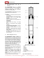
1.1
Technical data Hydrohammer® type S-70
Operating data
Max. net energy/blow
Min. net energy/blow
Blow rate @ max. energy
70
2
50
Weights
Ram
Hammer (incl. ram, in air)
Hammer (incl. ram, in water)
Hydraulic data
Average operating press.
Max. operating pressure
Max. oil flow
3,5
8,3
x,x
230
350
220
kNm
kNm
Blows/min
tons
tons
tons
bar
bar
l/min
Nitrogen filling pressures
Vertical pile driving only! Values will vary for pile driving under
different angles with the vertical
Supply accumulator
Return accumulator
Cap
Safety setting
Cap (rupture disc)
120-140
4-5
10-13
bar
bar
bar
40
bar
Connections
Oil supply 1 ¼ " hose (P)
38S/M52
male
Oil return 1 ¼ " hose (R)
38S/M52
male
Nitrogen/ air to cap (CA)
R 3/4"
male
See fig. 9 (page 13) for other connections
Lifting eyes
WLL
Working Load Limit
L1
25 tons
L2
9 tons
L3
9 tons
hole
diam.
Ø 52 mm
Ø 40 mm
Ø 40 mm
thick
ness
70 mm
40 mm
40 mm
Noise emitting data
Since the noise level highly depends on the applied
energy levels, pile caps etc., a range is given for
the equivalent A-weighted noise pressure level at
a distance of 1 m and at 1.6 m above the ground
level (average over 10 consecutive blows at 70%
of max. energy):
L A eq 90-98 dB(A)
With an optional sound enclosure, this level can be
reduced to 85 dB(A)
Fig. 1: Main dimensions
©
IHC Hydrohammer B.V. P.O. Box 26, 2960 AA Kinderdijk, The Netherlands,
1
Phone +31.78 6910302 Fax +31.78 6910304
Hydrohammer B.V.
Rev. 11/2003 User's manual S-70
Document no. S-70-05UMGB
1.2
The Hydrohammer®
features
S-70
and
its
The Hydrohammer® S-70 is a universal,
electronically controlled, hydraulic impact type of
hammer for steel piles. It is also suitable for
underwater operation with minor preparation
(contact IHC for further details).
The Hydrohammer® complies with the very strict
requirements of modern pile driving.
It provides:
- Possibility for underwater pile driving without
loss of energy.
- Control and read-out of the energy per blow,
permitting control of the entire piling
operation.
- Automatic protection for overload.
- Simple construction for easy operation and
maintenance.
- High reliability.
- Relatively high blow energy / net weight
ratio.
- No loss of performance after prolonged
operation.
- No requirement for hard wooden or synthetic
cap filling for hammer protection.
- Suitability for leader guiding or free riding
operation.
- No need of a guide cage. With a fixed pile
guide sleeve, the hammer can be placed
free on the pile.
- Possibility to drive batter piles up to 45° to
the vertical, with only a minor reduction of
the blow energy.
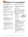
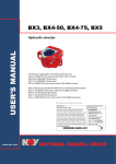
1.3
Main components (see fig. 2)
The Hydrohammer® basically consists of a
hydraulically driven ram weight (6), guided by oil
lubricated bushings in the upper ring (4) and the
lower housing (7). The piston at the upper part of
the ram weight (6) moves inside the cylinder (1).
The two supply- and two return accumulators,
located in the cap (2), are filled with Nitrogen at
one side of their internal floating piston (not
shown). The return and supply valves (3) are
externally mounted to the upper ring.
The two hose connections are located on the
connecting block (9) which is also mounted on
the upper ring.
The supply and return valves are identical and
therefore interchangeable, the same applies to
the accumulators.
Sensors (5), activated by the ram weight, are
installed in the housing (10) and supply the
signals to the electronic control system to
regulate the stroke and to measure the blow
energy.
Shock absorbers (8) are installed in the lower
housing to absorb the rebound of the pile.
1
2
3
4
5
6
7
8
9
10
Cylinder
Cap
Valves
Upper ring
Sensors
Ram weight
Lower housing
Shock absorbers
Connecting block with air connection
Housing
Fig. 2: Main components
©
IHC Hydrohammer B.V. P.O. Box 26, 2960 AA Kinderdijk, The Netherlands,
2
Phone +31.78 6910302 Fax +31.78 6910304
Hydrohammer B.V.
Rev. 11/2003 User's manual S-70
Document no. S-70-05UMGB
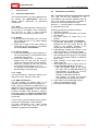
1.4
Operating principle (see fig. 3)
Fig. 3 shows schematically the hammer
operation. For the sake of clarity, the valves (2
and 7) and the accumulators (1 and 8) are drawn
outside the hammer.
At rest (not energized), both the return and
supply valves are open, allowing a continuous oil
circulation through the Hydrohammer® and the
hydraulic hoses with filtered oil from the power
pack.
Hammer cycle
When starting the Hydrohammer®, the return
valve (7) closes and the oil in the space (3)
under the piston (4) lifts the ram. At the end of
the lifting stroke, the supply valve (2) closes and
the return valve opens. The ram (10) is now
pushed downwards by its own weight and the
gas pressure on top of the piston.
At the end of the downward stroke (sensor B
"sees" ram weight), the return valve closes,
followed by the opening of the supply valve,
completing the cycle and a new cycle will start.
The suppletion valve (9) acts as a check valve,
enabling backflow of hydraulic oil to the piston of
the ram weight during the very short periods that
both supply and return valve are closed (after the
blow and ram in top position).
Cap pressure
A cap pressure below the value as specified in
par. 1.1 reduces the operating pressure and
maximum blow energy. On the other hand, a
higher cap pressure increases the operating
pressure and maximum blow energy.
Accumulators
The accumulators (1 and 8) reduce the pressure
and flow fluctuations between the continuous oil
flow from the power pack and the intermittent
flow in the hammer.
2
1
3
4
5
6
7
8
9
10
11
Blow energy
Blow energy is controlled by varying the time that
the return valve (7) remains closed during the
lifting stroke of the ram.
The energy, delivered to the pile, is measured for
every blow via sensors (see fig.2/5) and can be
selected for display on the control box, as well as
the blow rate and velocity.
Supply accumulat
valve
Supply
ors
Space under piston
Piston
Cap space
Cap fill connection
return valve
return accumulators
Suppletion valve
Ram weight
Sensor block AB
Fig. 3: Operating principle
©
IHC Hydrohammer B.V. P.O. Box 26, 2960 AA Kinderdijk, The Netherlands,
3
Phone +31.78 6910302 Fax +31.78 6910304
Hydrohammer B.V.
Rev. 11/2003 User's manual S-70
Document no. S-70-05UMGB
2.
COMMISSIONING
2.1
Checking of Hydrohammer®
(see fig. 4).
2.2
USE ONLY HOSES, supplied by IHC.
The Hydrohammer® S-70 is shipped:
o with the cap and accumulators pressurized at
the (max.) levels as specified in par. 1.1.
o with the hydraulic hose connections closed
by a "bleeding hose set".
This is done for safe depressurizing of the
possible pressure built-up in the internal
hydraulic oil circuit, due to gas leakage from
cap and accumulators.
This set-up also provides environmental
protection against oil spillage.
Perform the following checks with
Hydrohammer® in horizontal position:
Connection of hydraulic hoses
(see fig. 4)
Before connecting the hoses make sure that:
- the engine of the power pack is not in
operation,
- nobody is standing right in front of the hose
connections of the power pack,
- there are no traces of sand or dirt left in the
coupling nuts and connecting nipples. If
necessary clean the connections with engine
fuel.
Connect the hydraulic hoses (4) at the
connections (P) and (R) of the hammer and at
the power pack.
If, accidentally, the supply and return line have
been crosslinked, the Hydrohammer® will not
function properly. A pressure of 90 bar will be
indicated when the oil is circulated. As long as
the operating pressure is less than 200 bar, the
system will not be damaged.
the
1
2
Drain the cap as described in par. 4.2.3.
Drain any hydraulic oil leaked from the
housing at connection D2 (see fig. 7).
3 Check the oil level of the lower bearing at
connection F4 (see fig. 7) and top up if
necessary.
4 Depressurize hydraulic circuit of the hammer
with the bleeding hose set:
- Ensure both ball valves are in closed
position.
- Disconnect the small hose (3) at the arrow
from the ball valve at the press. connection
(P).
CAUTION
- Slowly open the ball valve at the return
connection (R) to depressurize the internal
hydraulic oil circuit. Collect the escaping
hydraulic oil.
- Reconnect the hose to the valve at
connection (P) and disconnect the small
hose from the ball valve at connection (R).
5
6
7
Open the ball valve at the pressure
connection (P) to drain and to collect any
remaining oil.
Reconnect the hose to the ball valve at (R),
disconnect both coupling nuts with blanking
plugs (2) and store it together with the valved
hose for later reuse in case of storage and
transport.
Check the pressure of the cap and the
accumulators using the nitrogen charge tool
(see par. 4.2.1 and 4.2.2).
1
2
3
4
Male stud coupling (remains on hammer)
Hose coupling nut with plug (remains on bleeder hose set
Bleeder hose set, including ¼” ball valves, nipples and
Interconnecting hose (L= 1500 mm)
Hydraulic hose 1 ¼” M52 (P & R)
Fig. 4: Hose connections
©
IHC Hydrohammer B.V. P.O. Box 26, 2960 AA Kinderdijk, The Netherlands,
4
Phone +31.78 6910302 Fax +31.78 6910304
Hydrohammer B.V.
Rev. 11/2003 User's manual S-70
Document no. S-70-05UMGB
2.3
Connection of control cable (see fig. 5)
The Hydrohammer® S-70 is shipped with the
control cable disconnected from the connecting
block (1) and with a transport cover (2) installed
at cable entry.
The procedure for connecting the control cable is
as follows:
1 Remove the transport cover (2) and put the
six socket head screws (3) aside for later use
(see step 6)
2 Remove the O-ring (6) from the cover and
place it on the special cable cover (4).
3 Pull the 14 pins connector (7) out of the
connecting block over approx. 20 cm.
4 Ensure that both connector parts are clean
and free of oil or water.
5 Connect the female connector (5) of the
cable cover to the corresponding male
connector (7). Tighten coupling nut until the
nut lock engages.
6 Slide the connector into the connecting block
and mount the cable cover to the connecting
block with the same six screws.
7 Store the transport cover conveniently for
later reuse (storage or transport).
2.4
Hammer positioning
Assumed is that all other associated equipment,
necessary for the intended piling operation
(leader-guided or free riding mode for vertical or
batter piling), is already installed.
1 Connecting block
2
Transport cover
3
Socket head screw
4
Cable end block
5
Female connector (14p)
6
O-ring
7
Male connector (14p)
Lift the Hydrohammer®, using the lifting eyes L1,
L2 and L3 (see fig. 9) as necessary, to place the
hammer in the required position.
Fig. 5: Connection of control cable
WARNING:
• The eccentricity of the hammer relative to the
pile shall be less than 2.5 cm.
• The angle between hammer and pile shall not
exceed 1:50.
©
IHC Hydrohammer B.V. P.O. Box 26, 2960 AA Kinderdijk, The Netherlands,
5
Phone +31.78 6910302 Fax +31.78 6910304
Hydrohammer B.V.
Rev. 11/2003 User's manual S-70
Document no. S-70-05UMGB
3.
OPERATION
3.1
Initial start of pile driving
3.4
The actual start and piling operation is controlled
from the portable control box C-32 or C-34.
See further the user's manual of control
equipment as purchased by the client.
3.4.1 Pile driving refusal
The refusal criteria at which pile driving
operations have to be stopped immediately and
beyond which the IHC warranty conditions do not
apply anymore are:
1
pile driving refusal is defined as the point
where the pile driving resistance exceeds:
either:
an average of 250 blows/25 cm (equivalent
to 300 blows/ft) pile penetration over six
(five) consecutive distances of 25 cm (1
foot).
This equivalent to a maximum of 1500
blows for a distance of 1,5 meter (5 feet) or
less,
or:
exceeds 650 blows per single distance of
0,25 m penetration (equivalent to 800
blows/ft)
Having properly started up the power pack
(engine speed approx. 1500 rpm, see power
pack manual) and with the Hydrohammer®
correctly placed in piling position, pile driving is
started by switching the START/STOP switch on
the control block in START position.
Check for any irregularities, such as jumping of
hoses, oil leakage etc.
3.2
Blow energy and blow rate
Because the setting of the energy level is time
based, the energy level at a certain cap
pressure, is determined by:
- oil flow (dictated by engine speed and
number of connected pump heads)
- position of the energy knob on the remote
control block (a higher value of lifting time
increases the lifting height of the ram weight,
at the same time reducing the blow rate).
2
It often appears that a lower blow energy at
higher blow rate is more productive than a higher
blow energy at a lower blow rate.
This shall not apply if there has been a
delay in pile driving operations for one hour
or longer.
For the first next 25 cm (1 foot), the blow
count may be 1000 as a maximum.
Thereafter the refusal criteria of point 1 shall
apply again.
Above blow count criteria represent very hard
driving conditions and have the purpose to
protect the hammer for mechanical breakdowns
or failures. In general one can consider a blow
count of approximately 80-100 bl/0,25 m (100125 bl/ft) at maximum pile driving energy as a
practical maximum.
A small increase in the Resistance to Driving
(SRD) will result in a large increase in blow
count, i.e. consequently also a large increase in
driving time.
The user will soon get the feeling for the optimal
settings of energy and engine speed (minimum
1500 rpm) for a particular soil resistance and
type of pile.
CAUTION
The cross-sectional area of the steel pile shall
not be less than 200 cm2 when applying full
energy.
3.3
Refusal criteria
3.4.2 Extraction refusal for upwards and
downwards blows
Penetration per blow
The Hydrohammer® will not stop when driving
piles through soft soil layers, unless the pile
drops dramatically
(trip 04: ram below sensor A).
In such situations it is recommended to keep the
blow energy low. When passing through thick
layers of very soft soil ("thick water"), where the
pile and hammer "sink", it is recommended to
stop the operation for a while.
See the separate documentation about the
refusal criteria for use of the IHC extraction cap
and extraction cat.
3.4.3 Rock breaking operation
See the separate documentation about the
refusal criteria for use of the IHC chisel set.
When driving piles in hard soil, the blow energy
must be increased.
©
IHC Hydrohammer B.V. P.O. Box 26, 2960 AA Kinderdijk, The Netherlands,
6
Phone +31.78 6910302 Fax +31.78 6910304
Hydrohammer B.V.
Rev. 11/2003 User's manual S-70
Document no. S-70-05UMGB
3.5
Stop / start of pile driving
3.8
Shutting down the Hydrohammer®
Pile driving should be stopped immediately after
trouble or an irregularity has been observed, so
as to prevent more damage.
At the end of the job, the Hydrohammer® will be
shut down and eventually prepared for storage or
transport.
Use the emergency stop on the control
equipment for emergency cases ONLY (both
engine of the power pack and piling operation
will stop immediately).
See the user's manual of the control equipment
how to RESET after an emergency stop.
o Depressurise the hydraulic oil system by
opening the bypass ball valves on the
hydraulic manifold (see user's manual of the
power pack)
o Disconnect the hoses
NOTE:
The hydraulic hose as supplied are equipped
with quick connectors (with integral check
valves) at the power pack side which makes
emptying of the hoses unnecessary (assuming
the hoses can be left connected to the hammer).
at hammer
In case the hoses need to be disconnected from
the hammer, the hydraulic hoses must be
emptied to the hydraulic reservoir for
environmental reasons:
- by making use of
gravity flow (with
hammer
in
vertical position)
and by opening
the
R
1/4"
aeration plugs on
the
connecting
block
(see fig. 6/V1 and
V2),
- screw and tighten the
plugs back in place,
Fig. 6: Aeration plugs
having completed emptying,
- disconnect the hoses from the hammer and
install the bleeder hose set, (see fig. 4) to the
P and R connections of the connecting block
- place the dust caps on open hose ends to
prevent entrance of dirt and moisture.
at power pack
- Disconnect the quick connectors of the
hydraulic oil hoses (P and R) at power pack
and place the dust caps to prevent entrance
of dirt and moisture.
Check for possible damage to the hoses.
Store the hoses at a proper place
If problems occur for which no solution can be
found in this manual, please contact
IHC Hydrohammer.
Pile driving should also be stopped when the
refusal criteria (as stated in 3.4 above) are
reached, in order to prevent damage to the pile
and hammer.
The piling operation can be stopped and
restarted with the STOP/START switch on the
remote control block at any time as long as no
automatic stops occur.
3.6
Automatic stops
The Hydrohammer® is stopped automatically
when a trip function is activated as indicated by
the trip code on the control box.
See the user's manual of the control equipment
how to RESET after an automatic stop.
3.7
Day's end of pile driving
At the day's end of pile driving, the
Hydrohammer system is stopped as follows:
- put stop/start switch S4 on control equipment
C-32 in STOP position (S5 on C-34),
- stop the engine as described in the power
pack manual.
- turn the power supply switch S1 on the
engine panel A-32 of the power pack in
position OFF
In case of prolonged idle operation (three days or
more); preservation of the hammer is required as
described in paragraph 6.3 Procedure for
preservation.
o Disconnect the control cable
- Disconnect the cable end block of the control
cable (see fig. 5 Pos 4/5) and store at a
proper place to prevent possible damage.
- Install the transport cover (fig. 5/2) on the
cable entry opening.
Put the hammer in horizontal position on wooden
blocks.
©
IHC Hydrohammer B.V. P.O. Box 26, 2960 AA Kinderdijk, The Netherlands,
7
Phone +31.78 6910302 Fax +31.78 6910304
Hydrohammer B.V.
Rev. 11/2003 User's manual S-70
Document no. S-70-05UMGB
4.
MAINTENANCE
4.1
Preventive maintenance
4.2
Maintenance procedures
4.2.1 Checking pressure of accumulators and cap
Too high or too low pressures in the
accumulators may cause the hydraulic hoses to
jump. The nitrogen charge tool is supplied to
check and correct these pressure levels.
See par. 1.1 Technical data, for pressure levels
of accumulators and cap.
The valves and sensors can all be replaced from
the outside. The Hydrohammer® does not
require internal inspections for preventive
maintenance.
4.1.1 Daily
Make an overall visual inspection of the hammer
for any sign of oil leakage, loose components
and the like. In case of loose screwed
connections, use the following torque values:
Checking procedure is as follows, see fig. 7:
1 Stop piling operation.
2 Stop the engine as described in the power
pack manual.
3 Put power switch on control box in OFF
position.
3a Only for checking the return accumulator
(to eliminate pressurizing by possible gas
leakage from the cap): Open the two ball
valves on the hydraulic manifold of the
powerpack to depressurize the system.
4 Install Nitrogen charge tool (see par. 4.2.2)
and ensure valves (1, 2 and 3) are closed.
5 Open slightly bolt (7) by turning spindle (5)
and read pressure on gauge (H), use gauge
(L) only for accurate reading of pressures
below 40 bar.
6 When pressure is too high, bleed off by
opening valve (2).
7 When pressure is too low: ensure valve 2 is
closed, close the spindle and proceed:
- Open the Nitrogen supply to the charge
tool, open valve (3) only half a turn and
read pressure on gauge (H); must be
higher than the required pressure.
- Charge by opening the spindle (5)
until pressure on gauge (H) indicates
required pressure and close the spindle.
8 Close valve (3) and the Nitrogen supply.
Open and close bleed valve (2)
9 Disconnect the Nitrogen supply.
4.1.2 Weekly
o Drain the cap (as described in par. 4.2.3) and
the housing (see par. 4.2.4), before starting
piling operation.
o Check the oil level of the lower bearing at
connection fig. 9/F4 and top up if necessary
with TOTAL FINA ELF DROSERA MS 68.
4.1.3 Every 3 months
o Check shock absorbers (visual inspection of
the shock absorbers is recommended when
exchanging the pile cap).
o Check the leakage rate of hydraulic oil,
drained from the cap and the housing,
measured over a full week of piling operation.
o Check the pressure of the cap and the
accumulators as described in par. 4.2.1.
It is strongly recommended to do this also at
the beginning of a new piling job.
4.1.4 Yearly
It is recommended to change the bearing oil at
least once a year. (See fig. 9 F4 en D3).
4.1.5 Major maintenance
The best indicator for internal wear of the
hammer is the leakage rate of the hydraulic oil.
Drain, collect and measure the total amount of
leakage oil from the cap and housing after a full
week of piling operation. If the amount
exceeds 50 l/week, closer attention is required.
From that moment on, logging of leakage rates
is recommended, and major maintenance must
be planned.
A cross check with the changes of the hydraulic
oil level in the powerpack is recommended.
All major maintenance work, which include
replacement of all seals, shall be done by
personnel, qualified to IHC standards.
©
IHC Hydrohammer B.V. P.O. Box 26, 2960 AA Kinderdijk, The Netherlands,
8
Phone +31.78 6910302 Fax +31.78 6910304
Hydrohammer B.V.
Rev. 11/2003 User's manual S-70
Document no. S-70-05UMGB
4.2.2 Installation of Nitrogen charge tool
Proceed as follows to mount the Nitrogen charge
tool to an accumulator or cap:
- close the valves (1), (2) and (3) for safety
reasons
- remove the plug from the accumulator
(connection F2 or F3) or the cap (connection
F1), using Allen key 12
- loosen bolt (7) by means of a 5 mm Allen key
- mount the gas connector assembly (4) by
turning the knurled ring (6) and make sure the
hexagon bottom of the spindle (5) falls into the
head of bolt (7).
- connect valve block with coupling nut (M) to
the Nitrogen supply.
See fig. 7.
At one side of the Nitrogen charge tool a
coupling nut (M) has been fitted for the Nitrogen.
Make sure that the correct connecting nipple has
been mounted with regard to the different
Nitrogen connections in the various countries
(see for details document 86 70 01 00).
Furthermore the Nitrogen charge tool is fitted
with a filling hose and gas connecting assembly
(4).
CAUTION
Keep valve (1) closed at all times when the
charge tool is connected to the hammer or gas
supply, to protect pressure gauge (L).
Removal of the Nitrogen charge tool is in
reversed order.
M
H
L
1
2
3
Coupling nut
Pressure gauge (250 bar)
Pressure gauge ( 40 bar)
Isolation valve for (L)
Bleed valve
Block valve
4
5
6
7
Connector assembly
Spindle
Knurled ring
Sealing bolt
Fig. 7: Nitrogen charge tool
©
IHC Hydrohammer B.V. P.O. Box 26, 2960 AA Kinderdijk, The Netherlands,
9
Phone +31.78 6910302 Fax +31.78 6910304
Hydrohammer B.V.
Rev. 11/2003 User's manual S-70
Document no. S-70-05UMGB
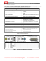
4.2.3 Draining oil from the cap
4.2.4 Draining oil from the housing
The procedure to drain the cap is as follows
(see fig. 8):
The procedure to drain the housing is as follows
(see fig. 9 for connecting points):
WARNING: The cap is normally pressurized!
-
-
remove the R 1/4" drain plug, marked D1B on
the upper ring,
connect the cap drain hose (3) (supplied as
special tool) to the drain opening and place
the end of the hose in a bucket,
remove the R 1/8" plug, marked D1A on the
upper ring (next to D1B),
screw the R 1/8" insert (2) (supplied as
special tool) in the drain opening, thus
opening the spring loaded ball (4),
collect the hydraulic oil, leaked into the cap,
after completion of drainage, remove the
hose and insert tool and install both plugs.
-
-
-
remove the R 1/2" drain plug, marked D4 on
the lower housing, when hammer is in vertical
position on the pile.
ATTENTION
Hammer must be on the pile, otherwise ram
weight may be resting on lower stop in the
housing, preventing full drainage of leakage
oil.
-
remove the R 1" drain plug, marked D2 on
the housing, when hammer is in horizontal
position.
1
2
3
4
Upper ring
Special tool 86 70 02 01 (insert for cap drain)
Cap drain hose, special tool 86 70 03 01
Ball
Fig. 8: Draining oil from the cap
©
IHC Hydrohammer B.V. P.O. Box 26, 2960 AA Kinderdijk, The Netherlands,
10
Phone +31.78 6910302 Fax +31.78 6910304
Hydrohammer B.V.
Rev. 11/2003 User's manual S-70
Document no. S-70-05UMGB
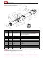
Replace stickers as soon as they are damaged or have become illegible.
Thoroughly clean the surface with a grease solvent, before applying the new sticker.
New stickers can be ordered from IHC Hydrohammer.
L3
C4
F4
Sensors A/B
E
C2
V1
L1
P R
L2
C3
PV
D3 D4
D2
RV
C1
SupV
V2
F2
D1B
F1
D1A
D1B
D2
D3
D4
P
PV
R
RV
SupV
C1-C4
L1
L2/L3
Sensors A/B
S1
V1
V2
E
R
P
R
D1A
F3
Indication
F1
F2
F3
P
F1
S1
S1
Connection Function
R 3/4"
Cap filling
R 3/4" (2x)
Filling P-Accumulators
R 3/4" (2x)
Filling R-Accumulators
R 3/4"
Oil fill lower bearing
R 1/8"
R 1/4"
R 1"
R 1/4"
R 1/2"
M 52
4 x M24
M 52
4 x M24
4 x M16
R 1"
ø 52 mm
ø 40 mm
6 x M12
R 1 1/4"
R 1/4"
R 1/4"
6 x M10
Cap drain
Cap drain
Drain, housing (horizontal)
Oil drain lower bearing
Drain, housing (vertical)
Hose connection oil supply
Pressure valve
Hose connection oil return
Return valve
Suppletion valve
Preservation
Lifting eye
Lifting eye
Cover for sensors A/B
Rupture disc
Aeration of P-hose
Aeration of R-hose
Control cable
Remarks
p = 10 - 13 bar, Allen key 12 mm
WARNING: Use Nitrogen only!
p = 120-140 bar, Allen key 12 mm
WARNING: Use Nitrogen only!
p = 4 - 5 bar
WARNING: Use Nitrogen only!
10 l, TOTAL FINA ELF DROSERA 68, Allen key 12 mm.
For batter piling at angles less than 45 º to the horizontal, use
TOTALFINAELF CARTER EP 230
Allen key 5 mm
See WARNING below.
Allen key 6 mm
See WARNING below.
Allen key 17 mm
Allen key 6 mm
Allen key 10 mm
Wrench 60 mm
Allen key 19 mm
Wrench 60 mm
Allen key 19 mm
Allen key 14 mm
Allen key 17 mm
WLL = 25 tons
WLL = 9 tons
Allen key 10 mm
40 bar
Allen key 6 mm
Allen key 6 mm
Allen key 8 mm
WARNING:
Always connect cap drain hose (special tool 86 70 03 01) first at D1B,
then depressurize with insert (special tool 86 70 02 01) at D1A.
Fig. 9: Location of various connections on the hammer S-70.
©
IHC Hydrohammer B.V. P.O. Box 26, 2960 AA Kinderdijk, The Netherlands,
11
Phone +31.78 6910302 Fax +31.78 6910304
Hydrohammer B.V.
Rev. 11/2003 User's manual S-70
Document no. S-70-05UMGB
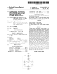
5.
TROUBLE SHOOTING
In this chapter, only the specific Hydrohammer® malfunctions will be discussed.
For malfunctions of the hammer which are normally related to incorrect situations in the powerpack or control
box, reference is made to the user's manual of the powerpack and control box.
Possible cause
1.
Remedy
®
Ram weight of Hydrohammer not moving
a Hammer not correct on pile (trip 11).
a Lamp A and or B on control box is not lit, see user's manual
of control box.
b Control cable not properly connected.
b Check connection at control box and connecting block on
hammer.
c Valve P or R malfunctioning.
c Pilot valve sticking or solenoid defective: replace or return for
repair.
d Incorrect situation at control box or powerpack.
d See user's manual of control box and powerpack.
2.
Jumping of hydraulic hoses
at initial start:
a Hydraulic hoses P and R are crossed
a Read working pressure on gauge panel, while circulating the
hydraulic oil (hammer not in operation).
If reading is 90 bar, correct hose connections.
during operation:
b Incorrect pressure in accumulators
b Check and correct as necessary, see par. 1.1 for pressure
levels.
3. Jumping of hammer on pile
a Cap pressure too high
a Check and correct cap pressure, see par. 1.1 for pressure
level.
®
4. Hydrohammer strikes irregularly
a Hydraulic oil supply to hammer too low.
a1 Increase engine speed or pump capacity.
a2 Ball valves on hydraulic manifold in open position, close
valves
b Pressure valve malfunctioning
(strong pressure fluctuations noticeable)
b Check pilot valve and solenoid.
c Return valve malfunctioning
c Check pilot valve and solenoid.
Table 1: Trouble shooting S-70
Standard Internal wiring 85 10 70 10
14 Pin AMP male connector
wire colour
Function
blue
1
green/yellow 2
black
3
brown
4
blue
5
brown
6
blue
7
brown
8
blue
9
10 thru 14
Sensor
Sensor
Sensor
Sensor
Pressure valve
Pressure valve
Return valve
Return valve
Reference
Not connected
Control cable 86 60 01 02 (L=50m)
14 Pin AMP female connector
16 p Walther Procon male connector
pin number
ABA+
B+
PP+
RR+
...........................................................................................................................................3
...........................................................................................................................................5
...........................................................................................................................................2
...........................................................................................................................................4
........................................................................................................................................ 12
........................................................................................................................................ 13
........................................................................................................................................ 14
........................................................................................................................................ 15
...........................................................................................................................................7
...........................................................................................................................................
Table 2: Connection internal wiring to control cable
©
IHC Hydrohammer B.V. P.O. Box 26, 2960 AA Kinderdijk, The Netherlands,
12
Phone +31.78 6910302 Fax +31.78 6910304
Hydrohammer B.V.
Rev. 11/2003 User's manual S-70
Document no. S-70-05UMGB
6.
STORAGE AND TRANSPORT
After completion of the shutting down activities
as described in par. 3.9, the hammer can be
prepared for storage or transport.
6.2
6.1
o In case of storage, or in case of transport
which takes 3 days or more and for seatransport.
o In case of prolonged idle operation (three
days or more).
Conditions for preservation
Provisions must be taken to preserve the
Hydrohammer® in the following cases:
Support of hammer
For storage and transport, the Hydrohammer®
must be placed in horizontal position with the
connecting block facing upwards.
The hammer can be supported by its own leader
boxes.
6.3
For transport, proper fixation of the hammer to
prevent movement during transport, is required.
Procedure for preservation
The procedure for preservation is as follows:
- Put the hammer in horizontal position.
- Remove the R1" plugs of the connections C1C4 (see fig. 9) and spray a liberal amount of
preservation fluid TOTALFINAELF OSYRIS DWX
9000 (formerly known as ELF PROTERA DR 07X)
(use an atomiser) through each opening.
Reinstall the plugs.
- Spray also a liberal amount of the
preservation fluid in the circumferential space
between the lower end of the ram and the
buffer locking plate.
WARNING:
In case of transport after any period of storage,
the cap pressure must be checked. The cap
pressure must be at least 5 bar, to prevent
movement of the ram during normal transport.
©
IHC Hydrohammer B.V. P.O. Box 26, 2960 AA Kinderdijk, The Netherlands,
13
Phone +31.78 6910302 Fax +31.78 6910304
Hydrohammer B.V.
Rev. 11/2003 User's manual S-70
Document no. S-70-05UMGB
©
IHC Hydrohammer B.V. P.O. Box 26, 2960 AA Kinderdijk, The Netherlands,
14
Phone +31.78 6910302 Fax +31.78 6910304