1
INSTALLATION, USE AND MAINTENANCE
MANUAL
SCOPE OF THIS MANUAL
SERIES H DIRECT EXPANSION
AND CHILLED WATER
AIR CONDITIONERS
www . tecnairlv . it
info @ tecnairlv . it
TECNAIR LV S.p.A
Via Caduti della Liberazione 53
21040 UBOLDO (VA)
Tel. +39029699111 / Fax +390296781570
Manuale cod. 75803307C.0807
“VERSIONE ORIGINALE”
Manuale cod. 75803307C.0807
Page 2 of 60
CONTENTS
1
HOW TO USE THIS MANUAL
5
1.1
5
IMPORTANT WARNINGS
2
WARRANTY
6
3
DESCRIPTION OF THE UNIT
7
3.1
3.2
UNIT CODE
OPERATING LIMITS
7
8
INSTALLATION PROCEDURE
9
4
4.1
4.2
4.3
4.4
4.5
4.6
TRANSPORTATION
RECEIVING THE MACHINES ON SITE
POSITIONING THE UNIT AND CLEARANCES
4.3.1
SHOCK-ABSORBING FEET
4.3.2
RAIN CANOPY
WATER CONNECTIONS
4.4.1
CONDENSATE DRAIN AND SIPHONS
4.4.2
WATER-COOLED CONDENSERS
4.4.3
WATER COILS
4.4.4
HEAT RECOVERY CIRCUIT
4.4.5
INTERNAL ELECTRODE HUMIDIFIER
4.4.6
MAINS STEAM VALVE
REFRIGERANT CIRCUIT CONNECTIONS
4.5.1
DISCHARGE OR HOT GAS LINE
4.5.2
LIQUID OR RETURN LINE
4.5.3
NON-RETURN VALVES ON DISCHARGE AND RETURN LINES
4.5.4
VERY LOW EXTERNAL TEMPERATURE KIT
4.5.5
SOLENOID VALVE ON THE LIQUID LINE
4.5.6
ROUTING OF THE REFRIGERANT CIRCUIT PIPES
4.5.7
DIAMETERS OF REFRIGERANT CIRCUIT CONNECTION PIPES
4.5.8
REFRIGERANT CHARGING
ELECTRICAL CONNECTIONS
4.6.1
INSTALLATION OF THE REMOTE CONTROL INTERFACE
4.6.2
INSTALLATION OF THE TEMPERATURE/HUMIDITY SENSOR SUPPLIED WITH
THE UNIT
4.6.3
INSTALLATION OF THE AMBIENT DIFFERENTIAL PRESSURE SWITCH
4.6.4
POSITIONING OF THE AMBIENT DIFFERENTIAL PRESSURE SWITCH
9
9
10
11
11
12
12
13
14
15
16
17
18
18
18
18
19
19
20
21
21
23
24
25
25
26
5
CHECKS AND FIRST STARTUP
27
6
DEACTIVATION, DISASSEMBLY AND SCRAPPING
30
7
USE OF THE AIR CONDITIONING UNIT
31
7.1
31
31
31
31
32
32
32
TEMPERATURE CONTROL
7.1.1
PROPORTIONAL CONTROL
7.1.2
PROPORTIONAL + INTEGRAL CONTROL
7.1.3
PROPORTIONAL + INTEGRAL + DERIVATIVE CONTROL
7.1.4
SERIES H DIRECT EXPANSION AIR CONDITIONERS
7.1.5
CHILLED WATER AIR CONDITIONER
7.1.6
COOLING CAPACITY CONTROL WITH HOT GAS INJECTION VALVE
7.1.7
COOLING CAPACITY CONTROL WITH HOT GAS INJECTION VALVE AND
ELECTRONIC EXPANSION VALVE
Manuale cod. 75803307C.0807
Page 3 of 60
33
7.2
7.3
8
9
10
HUMIDITY CONTROL
7.2.1
SERIES H DIRECT EXPANSION AIR CONDITIONERS
7.2.2
CHILLED WATER AIR CONDITIONER
7.2.3
SIMULTANEOUS HUMIDIFICATION AND COOLING
7.2.4
DEHUMIDIFICATION LOCK
SPECIFIC FUNCTIONS OF THE CONTROL SOFTWARE
7.3.1
NIGHT-TIME STAND-BY
7.3.2
UPS CONNECTION
7.3.3
“H – HR” HEAT RECOVERY SYSTEMS
7.3.4
SUPPLY TEMPERATURE CONTROL (LIMIT)
7.3.5
ANTIFREEZE SYSTEM
7.3.6
STERILIZATION CYCLE
7.3.7
EMERGENCY OPERATION WITH UNIT IN NEGATIVE PRESSURE
34
34
35
35
35
36
36
36
37
38
38
39
39
ROUTINE AND MAJOR MAINTENANCE
40
8.1
8.2
8.3
8.4
8.5
8.6
40
42
42
42
42
43
PROGRAMMED MAINTENANCE CHART
MAINTENANCE OF THE FANS
REFRIGERATION CIRCUIT CHECKS
MAINTENANCE OF THE ELECTRICAL BATTERY
MAINTENANCE OF THE ELECTRICAL PANEL
MAINTENANCE OF THE AIR FILTERS
WASHING, CLEANING AND DISINFECTION
44
9.1
9.2
9.3
9.4
44
44
45
45
WARNINGS
CLOTHING TO BE WORN DURING CLEANING OPERATIONS
CLEANING SYSTEMS
DISPOSAL OF USED CLEANING MATERIALS
FAULT DIAGNOSIS
46
10.1
10.2
10.3
10.4
10.5
10.6
47
49
51
52
53
55
MALFUNCTION OF THE FAN CONTROL INVERTER.
DIRECT EXPANSION AIR CONDITIONERS – REFRIGERATION CIRCUIT PROBLEMS
CHILLED WATER AIR CONDITIONERS – WATER CIRCUIT PROBLEMS
HEATING SECTION PROBLEMS
DEHUMIDIFICATION PROBLEMS
VENTILATION PROBLEMS
11
GLOSSARY
56
12
NOTES
57
Manuale cod. 75803307C.0807
Page 4 of 60
1
HOW TO USE THIS MANUAL
This manual describes the procedures for the installation, use and maintenance of series H air conditioning
units.
The following chapters contain information essential for obtaining the best performance from the unit you have
purchased; TECNAIR LV therefore recommends that you study this manual carefully.
Some of the topics covered in this manual refer to the functions of the microprocessor controls; TECNAIR LV
therefore advises you to read the MICROPROCESSOR CONTROL USER MANUAL, which is also supplied with the unit,
in order to gain a full understanding of the components and functions of your air conditioner.
If after reading this manual you are still experiencing difficulties or require any further clarification, please do not
hesitate to contact our after-sales service:
After-sales office
Tel. +39029699111 / Fax +390296781570
@ : info @ tecnairlv . it
1.1
IMPORTANT WARNINGS
The equipment described in this manual has been constructed to operate without risk for the intended
purposes, provided that:
•
•
The installation, connection, operation and maintenance of the appliance are carried out by qualified
personnel in accordance with the instructions contained in this manual.
All the conditions prescribed in the user manual for the unit’s microprocessor control are observed.
Any other use or modification of the equipment, unless expressly authorised by the manufacturer, is deemed
improper.
Any injuries or damage sustained as a result of improper use shall be the sole responsibility of the user.
Manuale cod. 75803307C.0807
Page 5 of 60
2
WARRANTY
TECNAIR LV air conditioners are subject to the following warranty conditions which are automatically deemed
to have been understood and accepted by the customer at the time of placing the order.
TECNAIR LV guarantees that the products supplied are well made and of good quality. It undertakes during the
period of warranty specified herein to repair or to replace with new at its own discretion, in the shortest time possible,
those parts found to present recognised defects in materials, construction or workmanship that render them unfit for the
intended use, provided that these faults are not the result of negligence on the part of the purchaser, neglect or
inexperience of the user, normal wear and tear, damage caused by third parties, acts of God or other causes not arising
out of manufacturing defects. TECNAIR LV however shall not be liable to for compensation for direct or indirect damage
of any nature incurred for any reason.
Defective components will be replaced at the Uboldo manufacturing plant, and all transportation and
replacement costs shall be borne by the Purchaser.
The duration of the warranty is 2 (two) years from the date of consignment.
The warranty shall be rendered void automatically if the equipment is repaired or modified or in any way
completed (such as, for example, in the case of non-supply of an electrical panel or similar) or in the case of the
installation of non-original parts (parts not supplied by TECNAIR LV).
The above warranty conditions apply provided that the Purchaser has fulfilled all contactural obligations and in
particular those reagarding payment.
Manuale cod. 75803307C.0807
Page 6 of 60
3
DESCRIPTION OF THE UNIT
The machine in question is an air conditioner with direct expansion or chilled water coil for surgical rooms and
medical environments.
The H series is characterised by perfect air-tight sealing, TUV certified and meeting class “B" requirements of
EN 1886. The cabinets are made of steel sheet with all joints welded and sealed with mastic. The cabinets are painted in
epoxy resin and oven cured at 150°C, after sandblasting, metalization and application of epoxy primer. The runners for
battery removal and all friction points are made from AISI 304 stainless steel. The buffer panels are 25 mm thick with
twins walls separated by thermal and accoustic insulation. The openable front panels are hinged and fitted with key
locks. The electrical panel is equipped with an emergency safety switch.
A version for outdoor installation (accessory) is also available; the outdoor version is equipped with an
anticondensation heater on the electrical panel, a microprocessor control protected from sunlight by a double access
panel to the electrical panel and a rain canopy. The buffer panels are of twin-wall construction with a thickness of 50 mm.
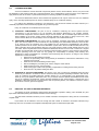
The machine comprises the following sections:
3.1
•
Electrical power and control panel
•
Ventilation section: consisting of one or more electric Plug fans mounted to the machine frame
•
Air treatment section:
•
Refrigeration circuit (Series A): comprising an expansion coil with copper prepainted aluminimum cooling fins,
a scroll compressor fixed to the machine frame on rubber mountings, thermostatic expansion valve, receiverdrier, plate-type condenser (accessory), low pressure switch (automatic reset) and high pressure switch
(manual reset).
•
Water circuit (Series U): with cooling expansion coil with copper pipes in prepainted aluminium cooling fins,
3-way motorised valve with manual emergency control, water circuit with anti-condensation thermal insulation
•
Heating and post-heating water coil with cooling coil with expanded copper pipes within prepainted aluminium
finning, 3-way motorised valve with emergency manual control; or electric low-thermal inertia with modulation
triac
•
Immersed electrode humidifier or modulating mains steam valve
UNIT CODE
The code contains the following information:
O
1
H
2
A
3
5
4
1
5
a
6
H
7
R407C
8
HR
9
1
O
Upflow air discharge
2
H
Series for surgical rooms or medical environments
3
A
4
5
Nominal size (nominal cooling capacity in TONS)
5
1
Number of cooling circuits or number of rows on chilled water coil
6
a
Series modification index
7
H
8
9
Cooling type:
A
Direct expansion coil with remote condenser
U
Chilled water coil with remote cooling
Air flow rate/cooling capacity ratio
H
High air flow rate
L
Low air flow rate
R407C Refrigerant type
HR
Air conditioner equipped with heat recovery system (if present)
Manuale cod. 75803307C.0807
Page 7 of 60
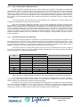
3.2
OPERATING LIMITS
SERIES H AIR CONDITIONING UNITS
UNIT TYPE
CHARACTERISTICS
MAXIMUM
TEMPERATURE
MINIMUM
TEMPERATURE
MAXIMUM
HUMIDITY
MINIMUM HUMIDITY
DIRECT EXPANSION
WITHOUT HEAT
WITH HEAT
RECOVERY
RECOVERY
L
H
+L
H
CHILLED WATER
WITHOUT HEAT
RECOVERY
WITH HEAT
RECOVERY
38°C
30°C
46°C
40°C
38°C
46°C
-22°C
-10°C
-40°C
-32°C
-22°C
-40°C
95%
95%
95%
95%
100%
100%
10%
10%
10%
10%
10%
10%
STORAGE
CONDITIONS
Temperatures from -20°C to +50°C
CONDENSERS AND DRY COOLER
UNIT TYPE
CHARACTERISTICS
AIR
WITH VARIATOR
Up to 30°C:
Up to 35°C:
Up to 40°C:
Up to 46°C:
MAXIMUM
TEMPERATURE
MINIMUM
TEMPERATURE
-25°C
WATER
WITHOUT
VARIATOR
∆T = 17°C
∆T = 15°C
∆T = 13°C
∆T = 10°C
-40°C
WITHOUT
PRESSURE
CONTROLLED
VALVE
WITH PRESSURE
CONTROLLED
VALVE
45°C
7°C
25°C
WATER CIRCUITS
TYPE
CHILLED WATER
HOT WATER
INTERNAL
HUMIDIFIER
MAINS STEAM
MAXIMUM
PRESSURE
16 bar (1.6 Mbar)
8.5 bar (0.85 Mbar)
8 bar (0.8 Mbar)
1 bar (0.1 Mbar)
MINIMUM
PRESSURE
-
-
1 bar (0.1 Mbar)
0.2 bar (0.02 Mbar)
MAXIMUM ∆P AT
VALVE
1 bar (100 Kpa)
1 bar (100 Kpa)
-
-
MAXIMUM
TEMPERATURE
-
85°C
40°C
152°C
MINIMUM
TEMPERATURE
5°C
-
1°C
-
Manuale cod. 75803307C.0807
Page 8 of 60
4
INSTALLATION PROCEDURE
4.1
TRANSPORTATION
Unless otherwise agreed with the Customer, TECNAIR LV shall supply their machines ex works with standard
packaging consisting of a wooden pallet and protective polythene sheet.
During transportation the machines must not be laid on their sides or overturned but must remain in the vertical
position at all times otherwise their internal components could be damaged.
As the Carrier is always responsible for damage sustained during transport by the goods, before signing the
delivery note to accept the supply, check the integrity of the packaging and that there are no visible signs of damage to
the conditioner or the leakage of oil or refrigerant.
In the case of evident damage to the unit or if there is slightest doubt as to whether the conditioner has been
damaged during transport, it is necessary to express your reservations in writing to the Carrier, whilst also informing the
TECNASIR LV Sales Department.
4.2
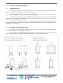
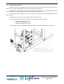
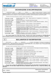
RECEIVING THE MACHINES ON SITE
For unloading of the units, please observe the procedures indicated in the illustrations reproduced below,
which are also affixed to the original packaging of the unit.
If the unit is not to be installed immediately after its arrival on site, it should remain in its original packaging and
stored in a dry, enclosed area, preferably heated to a temperature of 15°C during the winter months.
Manuale cod. 75803307C.0807
Page 9 of 60
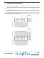
4.3
POSITIONING THE UNIT AND CLEARANCES
To avoid any problems and damage to the air conditioners during transportation, we recommend that the units
should only be removed from their packaging when they have reached their final destination.
It also essential to make sure that the floor on which the air conditioner is to be installed is capable of supporting
its weight. The weight of the unit can be found in the commercial documentation or read directly from the data plate
located inside the unit.
During installation, respect the clearances required for routine and major servicing indicated in the drawing
enclosed with the order confirmation.
In general and in any case it is essential to allow a space of approximately 1000 mm along the full length of the
front of the machine and 800 mm on the right-hand side; for units with rear opening, a free space of 1000 mm should be
provided along the full length of the rear of the machine.
Manuale cod. 75803307C.0807
Page 10 of 60
4.3.1
SHOCK-ABSORBING FEET
Before final positioning, install the shock absorbing feet supplied with the unit (accessory).
The feet are to be fixed to the underside of the unit using the bolts provided, as shown in the drawing enclosed
with the order confirmation.
4.3.2
RAIN CANOPY
Outdoor units are supplied with a rain canopy that is to be installed by the user. The rain canopy is to be fixed to
the top of the unit, as shown in the drawing enclosed with the order confirmation.
This canopy, while protecting the front of the unit from rain, does not guarantee safe servicing during inclement
weather. Therefore TECNAIR LV recommends that the unit is positioned under a further canopy to provide shelter during
any technical operations that may be required.
Manuale cod. 75803307C.0807
Page 11 of 60
4.4
WATER CONNECTIONS
WARNING!
TECNAIR LV tests water components with dried compressed air at 24 Bar.
This ensures that no water is present in the water circuits thereby preventing
the possibility of freezing during storage prior to installation.
However, during the positioning and installation operations, it is essential to
take special care not to fill the water circuits, even accidentally, before all the
necessary antifreeze measures stipulated in the design spefications have been
taken (e.g. insulation, addition of glycol, etc.).
4.4.1
CONDENSATE DRAIN AND SIPHONS
All air conditioners, whether direct expansion or water chilled coils, require a condensate drain connection
between the machine and the building waste drains system and the humidifier drain.
The siphon, essential for draining condensate as the relative bowl is located in a point of negative pressure,
is included in the supply and is to be installed when the unit the is placed in position.
Manuale cod. 75803307C.0807
Page 12 of 60
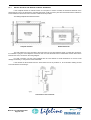
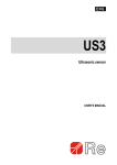
4.4.2
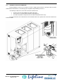
WATER-COOLED CONDENSERS
On machines with integral water-cooled condensers, it will be necessary to install the supply and drain lines to
the condenser. The diameters of the pipes and the inlet and the outlet unions are indicated in the order confirmation.
The water inlet unions on the plate-type condenser used by Tecnair are those at the bottom, while the outlet unions are
at the top, as shown in the figure below.
The pressure controlled valve (accessory) is essential when the water is supplied from a well, river or
acqueduct; it is not essential when the water is supplied from a water tower. In practice, the valve is necessary when
water during winter can enter at such low temperatures (e.g. below 15 degrees) that the machine’s condensation
temperature is lowered excessively. The valve is factory-installed on the condenser water inlet.
If the water supply is obtained from a well or river, two filters of suitable characteristics for the type of water must
be installed in parallel, (one as backup for the other) to prevent the condenser from becoming clogged by impurities in
the water.
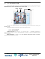
To ensure that circuit pipes are installed correctly, we recommend that the following indications are observed:
•
•
•
•
•
•
•
Use pipes made of copper or steel
Support pipes with suitable brackets (1)
Insulate both pipes with Armaflex type insulation (2)
Install shut-off valves to facilitate maintenance (3)
Install a Thermometer (4) and Pressure gauge (5) on the inlet and outlet
Install a drain outlet in the lowest part of the circuit (6)
Use a water/glycol solution where necessary
Manuale cod. 75803307C.0807
Page 13 of 60
4.4.3
WATER COILS
For machines with chilled water coils, as for those with hot water coils, it will be necessary to install inlet and
outlet pipes. The diameters of the pipes and the inlet and the outlet unions are specified in the order confirmation.
The water inlet and outlet unions are indicated in the figure below. The unions can also be identified by their
adhesive labels.
The maximum pressure of the water supply to the coils is 16 bar (1.6 Mpa). The maximum pressure difference
between the water inlet pipe and the outlet pipe is 1 bar (100 kPa), as at pressure differences greater than this value the
return spring would not be able to shut off the water flow. In the event of greater pressure differences, it will be necessary
to install a pressure reducing valve upstream of the 3-way valve.
To ensure that circuit pipes are installed correctly, we recommend that the following indications
are observed:
•
•
•
•
•
•
•
Use pipes made of copper or steel
Support pipes with suitable brackets (1)
Insulate both pipes with Armaflex type insulation (2)
Install shut-off valves to facilitate maintenance (3)
Install a Thermometer (4) and Pressure gauge (5) on the inlet and outlet
Install a drain outlet in the lowest part of the circuit (6)
Use a water/glycol solution where necessary
Manuale cod. 75803307C.0807
Page 14 of 60
4.4.4
HEAT RECOVERY CIRCUIT
TECNAIR LV does not fill the heat recovery circuit in the factory as the percentage of glycol to be added to the
water will vary according to the installation site and the minimum winter temperature.
It essential to use a water/glycol solution whenever there is the possibility that the outside temperature may fall
below zero degrees. When filling the circuit, always add the glycol first, then the water.
If the system is stably connected to the mains water supply, a shut-off cock must be installed upstream of the
mains connection.
A manual drain cock for the circuit is provided under the expansion vessel.
Below are indicated the total capcities in litres of the air conditioner heat recovery circuits:
•
•
•
36 litres for model sizes 62 to 138;
48 litres for model sizes 152 to 208;
67 litres for model sizes 242 to 308;
Remember that if the circuit is filled with a water/glycol solution, it must not be drained into the main sewer.
Manuale cod. 75803307C.0807
Page 15 of 60
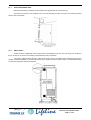
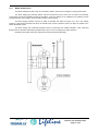
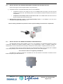
4.4.5
INTERNAL ELECTRODE HUMIDIFIER
During installation of the unit it is necessry to connect a supply pipe (as shown in the figure) with the system
characteristics indicated below. The discharge pipe is supplied ready-installed by Tenciar LV.
The following conditions for correct water connection should be met:
•
•
•
A shut-off cock must be installed in the water supply pipe
There must be a mechanical filter installed on the supply line
The water temperature and pressure must be within the permitted value range
For more information of the characteristics of the humidifier water circuit, please refer to the User manual for the
internal humidifier.
Manuale cod. 75803307C.0807
Page 16 of 60
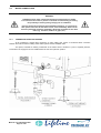
4.4.6
MAINS STEAM VALVE
The steam distribution systems may be connected to boilers, steam heat exchangers or existing steam users.
The steam supply pipe, perfectly drained, must be connected to the top of the unit, as shown in the drawing,
so that there is downward gradient towards the humidifier. A shut-off damper (to be supplied by the installer) must be
installed upstream of the system. We recommend using a pressure gauge.
The steam supply pressure must be as stable as possible and within the range of 0.2 and 1 bar relative
pressure. If the pressure exceeds this value, the installer must provide a pressure reducer to adapt the system to the
steam distribution system.
The steam supply and condensate drainage must be constructed from suitable materials. Joints, seals and
flanges must be capable of withstanding temperatures of up to 152°C according to the supply pressure.
Drainage of the steam mains pipe under pressure must be achieved efficiently.
Manuale cod. 75803307C.0807
Page 17 of 60
4.5
REFRIGERANT CIRCUIT CONNECTIONS
The pipes must be made from Gelidus type copper, soft annealed copper for pipes with diameters 26 - 28,
and hard drawn for larger diameter pipes.
To prevent copper dust or swarf from getting into the system, the pipes should be cut using a pipe cutter rather
than a hacksaw. The ends of the pipes should then be carefully cleaned.
If the ends are to be soldered, they should be cleaned with grade 00 glasspaper to eliminate all oxidisation and
dirt. After which the pipe should be inserted in the joint and heated evenly to the melting point of the solder so that flows
easily around the joint.
It is important to remember that the pipes should be as short as possible with bends kept to a minimum, as the
cooling capacity of the circuit can be summarised as follows:
Total length of the pipes (discharge and return):
•
•
•
4.5.1
> 20 m: - 2%
> 40 m: - 4%
> 60 m: - 6%
DISCHARGE OR HOT GAS LINE
This is the refrigerant line that connects the compressor outlet to the air-cooled condenser inlet.
To facilitate connection inside the air conditioner, there is a section of pipe approximately 20 cmm long with one
end connected to the compressor outlet and pinched and soldered shut at the other end.
During operation of the air conditioner, the discharge pipe reaches a temperature of 70 - 80°C. Thermal
insulation of this pipe is not necessary as dispersion of heat along this section favours the refrigeration cycle. The pipes
should only be insulated for safety reasons in cases where there is a possibility that someone could come into accidental
contact with the discharge pipe.
4.5.2
LIQUID OR RETURN LINE
This is the pipe that conects the condenser outlet to the air conditioner inlet valve.
It is connected by soldered joints to the condenser and to the inlet valve. The operating temperature of this pipe
is about 40°C; it does not need to be thermally insulated except in cases where the air conditioning system is also to
operate in winter with temperatures below zero.
4.5.3
NON-RETURN VALVES ON DISCHARGE AND RETURN LINES
WARNING!
In installations with refrigeration circuit pipes longer than 10 metres with vertical pipe runs and the condenser
located higher than the machine, it will be necessary to install a non-return valve on the refrigerant discharge
pipe as near as possible to the compressor outlet.
This will prevent the refrigerant, in the event of the compressor shutdown, from flowing back down the discharge
pipe to the compressor and thus damaging it at the next startup and/or preventing normal operation by causing a highpressure blockage. Naturally the valve must be installed vertically and the right way round in accordance the refrigerant
direction of flow.
In the case of pipe sections more than 20 m long and expected minimum temperatures below –10°C it will be
necessary to install another non-return valve at the outlet of the air condenser, and as close to it as possible; the valve
should be installed vertically to prevent the refrigerant from flowing back to the condenser when the system is off and the
external temperature is very cold, and thereby preventing efficient condensation of the refrigerant the next time the
compressor is started.
Manuale cod. 75803307C.0807
Page 18 of 60
4.5.4
VERY LOW EXTERNAL TEMPERATURE KIT
CEA air condensers, combined with Tecnair LV direct expansion air conditioners, are equipped as standard with
air condensation pressure control via reduction of the air flow rate in accordance with the reduction in the condensation
pressure. This system is very effective with external temperatures down to –20°C, thanks also to a few seconds delay
before the low pressure switch trips at compressor startup. At external temperatures below this level and above all in the
case of lengthy periods of non-use of the refrigeration circuit, the temperature of the liquid refrigerant can become so low
that, in spite of the above-mentioned delay, the low pressure switch trips on compressor startup, thus making starting
impossible.
To avoid this problem, we recommend the “very low temperature kit”, comprised of a condenser flooding valve
installed on the refriegerant connections of the air condenser.
When the condensation temperature falls below +40°C, the valve progressively closes the condenser outlet,
thereby flooding it and reducing proportionally the heat exchange. The refrigerant that bypasses the condenser is
gaseous and at high temperature; it mixes with the liquid refigerant at very low temperature at the condenser outlet, so
that the resulting temperature is such to permit the successful system startup. The volume of refrigerant present in the
circuit must therefore be sufficient to be able to almost completely flood the condenser coil. During summer operation
instead, the condenser coil must be almost completely free of liquid refrigerant in order to operate correctly. An oversize
receiver is therefore installed in order to accommodate in summer the quantity of refrigerant that is required in winter to
flood the condenser.
4.5.5
SOLENOID VALVE ON THE LIQUID LINE
The scroll compressors installed on TECNAIR LV air conditioners will not be damaged by the presence of any
liquid refrigerant in the crankcase. However, when the refrigeration ciruit is shutdown in the summer season, i.e. when
the external temperature is just a few degrees higher than the internal temperature, the liquid refrigerant flows towards
the compressor (the coldest point of the circuit) and, depending on the quantity of refrigerant in the system, floods it
partially or completely. In this case, the high pressure switch may trip at the next startup.
It is therefore necessary to compare the refrigerant charge in the circuit, calculated as the sum of the contents of
the various components of the circuit, with the maximum quantity compatible with correct operation without the solenoid
valve on the liquid pipe, as indicated in the table below.
Size
Compressor
Rated power (Hp)
Rated power (kW)
Maximum quantity of refrigerant (kg)
21
2
6
2,8
31
3
10
3,6
41
3,5
11
5,4
51
5
15
5,4
71
6,5
19
5,4
81
7,5
25
7,3
101
10
30
10,0
131
12
36
12,5
151
15
45
13,5
Table of maximum compatible refrigerant quantities per circuit without installation of solenoid valve on liquid pipe.
In the case that the calculated charge is greater than the maximum compatible quantity, it will be necessary to
order the “liquid pipe solenoid valve” accessory which, by closing when the compressor is shut down, prevents the
refrigerant flowing back towards the compressor through the liquid pipe.
Obviously it is also necessary to prevent refrigerant from flowing back to the compressor through the discharge
line. This is achieved by installation of the non-return valve on the discharge line. The latter valve, unlike the solenoid
valve, is not offered by TECNAIR LV as an optional accessory as it must be installed when the refrigeration circuit
external to the machine is installed, while the solenoid valve is installed inside the machine itself.
Manuale cod. 75803307C.0807
Page 19 of 60
4.5.6
ROUTING OF THE REFRIGERANT CIRCUIT PIPES
Correct routing of the refrigerant circuit pipes is essential to the successful operation of the air conditioner. It is
necessary to take special care in the selection and positioning of the compressor discharge and suction pipes, above all
when these lines are relatively long and in particular:
•
Horizontal sections of discharge pipes between the inside and outside components must have a gradient of at
least 2% in the direction of refrigerant flow.
•
If the discharge pipe has to rise above 3 m, a siphon with the minimum radius bend possible must be installed
immediately before each rising section.
•
Additional siphons must be provided every 3 m of rising pipe.
•
Position a counter-siphon near the condenser union. The counter-siphon must be at least as high as the
highest part of the condenser coil;
•
All pipes must be secured with brackets every 2 metres. The pipe supports should prevent transmission of
vibration and at the same time allow for normal expansion and contraction of the pipes due to temperature
changes during operation.
•
A 1/4" service valve must be installed on both pipes, as near as possible to the outside unit, to allow draining
and charging of the circuit.
•
The refrigerant inlet and outlet unions on the air-cooled condenser can be identified by their adhesive labels.
In any case, note that the exchange of heat between the air and the refrigerant should occur in the opposite
direction to the flow. This means that the condenser inlet union for the gaseous refrigerant is the union
furthest from the air inlet into the coil, i.e. the union nearest the fans. Likewise, the condenser outlet union for
the liquid refrigerant is the union furthest away from the fans.
Manuale cod. 75803307C.0807
Page 20 of 60
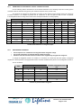
4.5.7
DIAMETERS OF REFRIGERANT CIRCUIT CONNECTION PIPES
Use the following table to determine the recommended diameters for the discharge, liquid and suction pipes in
accordance with the machine size (given by the numerical sequence in the product code).
The values in the columns for pipe lengths up to 30m are also valid for longer lengths and do not need to be
increased. However, it is advisable to position the air conditioners so that the pipes are kept as short as possible,
to avoid significant loss of charge in the circuit and a consequent reduction in cooling capacity.
Size
Compressor
Pipes up to 15 m long
Rated power (Hp) Rated power (kW) Discharge
Pipes 15 to 30 m long
Liquid
Suction
Discharge
Liquid
Suction
51
5
15
16/18
10/12
26/28
20/22
14/16
26/28
81
7,5
25
20/22
14/16
26/28
26/28
14/16
33/35
101
10
30
20/22
14/16
33/35
26/28
16/18
33/35
151
15
45
26/28
16/18
33/35
26/28
20/22
39/42
102
2×5
2×15
2×16/18
2×10/12
2×26/28
2×20/22
2×14/16
2×26/28
132
2×6,5
2×19
2×16/18
2×10/12
2×26/28
2×20/22
2×14/16
2×33/35
152
2×7,5
2×25
2×20/22
2×14/16
2×26/28
2×26/28
2×14/16
2×33/35
202
2×10
2×30
2×20/22
2×14/16
2×33/35
2×26/28
2×16/18
2×33/35
242
2×12
2×36
2×26/28
2×16/18
2×33/35
2×26/28
2×16/18
2×39/42
302
2×15
2×45
2×26/28
2×16/18
2×33/35
2×26/28
2×20/22
2×39/42
Inside/outside diameters of refrigerant pipes
4.5.8
REFRIGERANT CHARGING
•
•
•
Direct expansion air conditioners are shipped without refrigerant charge.
Air-cooled condensers are shipped without refrigerant charge.
Machines with internal water-cooled condensers are supplied fully charged with refrigerant
To charge the refrigerant circuit/s of a machine, it is necessary to consider that the total quantity of refrigerant
required for a direct expansion unit equipped with remote condenser is determined by the sum of the refrigerant contents of:
The air conditioner:
Compressor
Rated power (Hp)
Rated power (kW)
Contents of refrigerant circuit
(kg)
51
5
15
0,8
71
6,5
19
0,8
71
6,5
19
0,9
81
7,5
25
1,2
101
10
30
1,6
151
15
45
1,9
Size
Contents of pressurization refrigerant
Manuale cod. 75803307C.0807
Page 21 of 60
Discharge pipe and liquid pipe:
Weight in kg per metre of pipe (R407C)
Diameters
Ø 10/12
Ø 12/14
Ø 14/16
Ø 16/18
Ø 20/22
Ø 26/28
Ø 33/35 Ø 39/42
Liquid pipe
0,08
0,11
0,15
0,20
0,31
0,53
0,94
1,31
Discharge pipe
0,02
0,03
0,05
0,06
0,09
0,16
0,26
0,36
Weight of refrigerant in pipes
Air-cooled condensers with CEA axial fans:
Model
Contents of refrigerant
circuit (kg)
Model
Contents of refrigerant
circuit (kg)
CEA 21c H/V
0,66
CEA 91c H/V
3,8
CEA 21c/LN H/V
1,0
CEA 101c H/V
5,2
CEA 31c H/V
1,32
CEA 101c/LN H/V
4,0
CEA 31c/LN H/V
2,0
CEA 111c H/V
5,3
CEA 41c H/V
1,32
CEA 111c/LN H/V
6,0
CEA 41c/LN H/V
1,9
CEA 121c H/V
4,0
CEA 51c H/V
1,95
CEA 121c/LN H/V
7,3
CEA 51c/LN H/V
2,9
CEA 131c H/V
4,0
CEA 61c H/V
2,58
CEA 131c/LN H/V
8,0
CEA 71c H/V
1,89
CEA 151c H/V
6,0
CEA 71c/LN H/V
3,6
CEA 181c H/V
8,0
CEA 81c H/V
2,88
CEA 181c/LN H/V
8,0
CEA 81c/LN H/V
4,0
CEA 201c H/V
10,5
Refrigerant contents of the circuit
The sum of the refrigerant contents (air conditioner + liqid pipe + discharge pipe + condenser) gives the total
refrigerant charge required by the system:
Refrigerant contents of air conditioner OHA 51H:
Refrigerant contents of condenser CEA 61:
10 metres of 16/18 diameter discharge pipe = 0.06 kg/m x 10 =
10 metres of 10/12 diameter liquid pipe = 0.08 kg/m x 10 =
0,8
2,6
0,6
0,8
Total refrigerant content:
4,8
Obviously machines with two refrigerant circuits (e.g. models 202), the charge for each circuit is to be calculated
in the same way as model 101 machines.
It is also necessary to add oil to the circuit in a quantity equal to approximately 5% of the total amount of
refrigerant in the circuit. We recommend the use of SUNISO 3 GS for machines charged with R22 and
MOBIL EAL ARTIC 22 BC or equivalent polyesters for machines charged with R407C.
Manuale cod. 75803307C.0807
Page 22 of 60
4.6
ELECTRICAL CONNECTIONS
WARNING!
BEFORE CARRYING OUT ANY OPERATIONS ON THE UNIT, SET THE MAIN
SWITCH TO POSITION “O”
The external electrical connections of the air conditioner must satisfy the following preseciptions:
•
They must be suitably dimensioned to withstand the maximum load in Amperes indicated on the electrical
wiring diagram and on the data plate located inside the electrical compartment of the unit itself.
•
The power supply must be within the following limits in order to avoid possible malfunction of the installed
components:
o
o
Voltage tolerance limits: ± 10%
Frequency tolerance limits: ± 2%
•
The power supply line from the external RCBO (Residual Current Breaker with Overcurrent protection) to the
machine must be direct without any interruptions or junctions.
•
The thermal-magnetic circuit breaker, the installation of which is responsibility of the Customer, is essential in
order to provide overcurrent protection on the supply line (Articles 7.2.1 and 7.2.6 of standard CEI EN 60204-1),
and must be located as near as possible to the machine. The thermal magnetic circuit breaker must be equipped
with a residual current device (RCD) with a trip settings of 30 - 300 mA to provide protection for persons against
both indirect and direct contact, in addition to thermal and magnetic overload protection. The RCD serves also to
protect the air conditioner against insulation failure.
•
The earth connection must be made with a conductor having the minimum cross-section indicated in the
wiring diagram.
•
To prevent operating problems with the microprocessor controls, it is necessary that no other loads (pumps,
condensers, etc.), even those that are part of the same system, are connected downstream of the main switch of
the air conditioner, unless explicit permission is granted by TECNAIR LV. If this condition cannot be met, it will
be necessary to connect suppressors (R + C) in parallel with the coils of the relays of any such loads.
•
The signal/control cables must be kept separate from high-current cables, power cables and any cables that
are potential sources of electromagnetic interference.
•
To avoid possible damage to electrical and electronic equipment, particularly in outdoor units, caused by
voltage surges in the electrical supply line, TECNAIR LV recommends evaluating the necessity of installing
SPDs (Surge Protection Device) appropriately rated for the type of installation and the frequency of direct
lightning strikes on the electrical supply line.
Manuale cod. 75803307C.0807
Page 23 of 60
4.6.1
INSTALLATION OF THE REMOTE CONTROL INTERFACE
If the complete terminal or reduced version is to be panel or recess mounted, the maximum thickness of the
panel must be 6 mm; if the terminal is to recessed mounted in a wall, a masonry box with internal dimensions sufficient to
accommodate the terminal and the connection cables must be provided.
The drilling templates are illustrated below:
Complete terminal
Reduced terminal
The user terminal is to be conected to the main board via a 6-wire telephone cable. To make the connection,
it is sufficient to plug one of the telephone connectors into one of the terminals of the TCON6 board and the other into the
terminal connector, as shown in the wiring diagram.
For safe connection, use the toroid supplied with the user terminal to avoid interference on the line could
damage the memory or components of the board itself.
If the terminal is disconnected from the board when the unit is powered on, we recommend waiting at least
5 seconds before reconnecting it.
--{}-{}Connection of user terminals
Manuale cod. 75803307C.0807
Page 24 of 60
4.6.2
INSTALLATION OF THE TEMPERATURE/HUMIDITY SENSOR SUPPLIED WITH THE UNIT
There are two types of sensor supplied with the unit (accessories):
1)
2)
Temperature sensor or temperature/humidity sensor for duct installation:
•
Temperature sensor for the supply air duct: To be installed inside the supply air duct at the point
nearest to the outlet vents. The humidity sensor is to be installed on board the machine in the return air
compartment.
•
Temperature and humidity sensor for the retun air duct To be installed inside the return air duct at
the point nearest to the return air inlet vents.
Wall-mounted temperature sensor or temperature/humidity sensor: To be installed in the room to be
controlled at a height of approximately 1.7 m.
Take care during sterilization to protect the sensor to prevent damage to the electronic components!
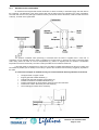
4.6.3
INSTALLATION OF THE AMBIENT DIFFERENTIAL PRESSURE SWITCH
The differential pressure switch installed in the room to be controlled is of fundamental importance in that it
continuously transmits the ambient pressure reading to the microprocessor control. It therefore enables the
microprocessor control to take the actions necessary to maintain the correct positive or negative pressure in the room.
The pressure switch uses two aeraulic inputs and an electrical terminal block to be connected with a shielded
3x0.35 cable (AWG22) to the terminal block of the electrical panel, as shown in the wiring diagram.
The connection cable is not supplied by TECNAIR LV.
The difference in pressure between the controlled room and the reference environment is measured via two
flexible transparent pipes with diameter 4/7.
Manuale cod. 75803307C.0807
Page 25 of 60
4.6.4
POSITIONING OF THE AMBIENT DIFFERENTIAL PRESSURE SWITCH
The pressure switch can be positioned in various ways. The following figures show the typical types of
installation. Wherever you decide to install the pressure switch, the following points are essential
•
Connect the pipe with the free end in the room to the positive socket of the differential pressue
switch, even in the case of negative room pressure, protruding a few centimetres from the wall or
ceiling.
•
Ensure the pressure switch is at least 2 metrs from the floor level, so that it is better protected
against dust deposits or possible impact.
Installing the differential pressue switch in the room
Installing the differential pressure switch in an environment adjacent to the room
Installing the differential pressure switch in the room
Manuale cod. 75803307C.0807
Page 26 of 60
5
CHECKS AND FIRST STARTUP
WARNING!
BEFORE CARRYING OUT ANY OPERATIONS ON THE UNIT, SET THE MAIN
SWITCH TO POSITION “O”
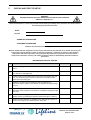
Before the Mnufacturer’s personnel proceed with the testing and startup of the machines, the checks listed in
the following form must be carried out.
DATE
PLACE
OPERATOR’S SIGNATURE
CUSTOMER’S SIGNATURE
Checks to be carried out before calling technician for startup
Machine startup with the refrigeration circuit requires that the units are powered on for at least two hours prior
to the arrival of the technician in order to allow the compressor’s crankcase oil heater to reach working
temperature and allow evaporation of any refrigerant deposited in the compressor to ensure that the
compressor/s function/s correctly. The crankcase heaters switch on automatically when the machine is
powered on.
REFRIGERANT CIRCUIT CHECKS
DESCRIPTION
1
Check discharge pipe diameter conforms with indication in the installation
manual.
2
Check “horizontal” sections of the discharge line have a gradient of at least
1% in direction of refrigerant flow
3
Check that siphons are installed at the lowest point of each rising pipe and
every 3 m along rising pipe sections, as well as a counter siphon at the
highest point of the rising pipe.
4
Check the non-return valve is installed as near as possible to the
compressor with the apertue in the direction of refrigerant flow (pipes longer
than 5 m).
5
Check the non-return valve is installed as near as possible to the
compressor with the aperture in the direction of refrigerant flow (pipes longer
than 10 m).
6
Check that the discharge pipe is insulated in the sections where accidental
operator contact is possible (pipe operating temperature approx. 70/80°C)
7
Check that support brackets are installed on the discharge pipe every 3 m
and are not too tight so as to allow expansion of the pipe.
POSITIVE
NEGATIVE
Manuale cod. 75803307C.0807
Page 27 of 60
8
Check that the diameter of the liquid pipe conforms to requirements.
9
Check that support brackets are installed every 3 m.
10
Check that refrigerant circuit valves are open, including the valve on the hot
gas injection pipe.
11
Check the electrical connections to the condenser disconnect switch.
12
Check that the disconnect switch is in the closed position (condenser
powered on).
13
Check the refrigerant pipe connections between the condenser and the
evaporator are in the opposite direction to the air flow and the refrigerant
flow.
14
Check that the condenser is correctly popsitioned far away from walls and/or
other condensers to avoid recirculating air currents that could impair its
operation.
15
Check the charge level in the refrigerant circuit.
16
Check the evaporation pressure.
17
Check the condensation pressure.
18
Check the superheating of the refrigerant aspirated by the compressor.
19
Check the subcooling of liquid refrigerant.
20
Check that the liquid line filter is not clogged.
21
Check the power consumption of the compressor.
22
Check operation of the high pressure control switch.
23
Check operation of the low pressure control switch.
24
Check the compressor operating temperature.
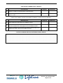
WATER CIRCUIT CHECKS
DESCRIPTION
25
Check that the inlet and outlet of the hot and cold water supplies conform
with the arrows marked on the fittings or, if these are missing, with the
drawings in the installation manual of the machine.
26
Check that all the liquid supply pipes are provided with manual shut-off
cocks just outside to the machine, and that theses cocks are open.
27
Check that the condensate drain outlet does not have taps or restrictions.
28
Check that the hardness of the water supply is between 10 and 40 French
degrees.
29
Check that the humidifier supply fitting is connected to the mains drinking
water supply and that it is provided with a manual shut-off valve just outside
the machine.
Manuale cod. 75803307C.0807
Page 28 of 60
POSITIVE
NEGATIVE
ELECTRICAL POWER SUPPLY CHECKS
DESCRIPTION
30
Check the connetion of the three phases, neutral and earth.
31
Check that the power supply voltage and frequency are within the tolerance
limits of +/- 10%.
POSITIVE
NEGATIVE
CHECKS FOR AMBIENT SENSOR AND REMOTE TERMINAL CONNECTIONS (IF PRESENT)
DESCRIPTION
32
Check positioning as prescribed in the installation manual.
33
Check that electrical connection between the sensors and the electrical
panel is as indicated in the wiring diagram and the installation manual.
34
Check the installation and connection of the ambient pressure switch is as
indicated in the wiring diagram and installation manual.
POSITIVE
NEGATIVE
NOTES ON ANOMALIES ENCOUNTERED DURING CHECKS
…………………………….……………………………………………………………………………………………………………
…………………………….……………………………………………………………………………………………………………
…………………………….……………………………………………………………………………………………………………
…………………………….……………………………………………………………………………………………………………
Manuale cod. 75803307C.0807
Page 29 of 60
6
DEACTIVATION, DISASSEMBLY AND SCRAPPING
WARNING!
BEFORE CARRYING OUT ANY OPERATIONS ON THE UNIT, SET THE MAIN
SWITCH TO POSITION “O”
TECNAIR LV air conditioners must only be dismantled by specialised technical personnel. In any case,
the following points must be observed:
•
Switch off the air conditioner first by way of the microprocessor control
•
Open the machine’s main door lock switch
•
Open the external thermal-magnetic circuit breaker to isolate the air conditioner from the electrical
power supply
•
The refrigerant contained in the air conditioner should be disposed of in accordance with the waste disposal
and safety regulations applicable in the country of installation.
•
Disconnect, where applicable, the refrigerant lines, the water connections and the condensate drain lines
from the air conditioner.
•
The scrapping of air conditioner is subject to the prevailing legal requirements in the country of installation.
•
TECNAIR LV recommends that you contact an authorised waste disposal contractor for this purpose.
•
Air conditioners are made primarily from raw materials such as aluminium, copper and steel.
Manuale cod. 75803307C.0807
Page 30 of 60
7
USE OF THE AIR CONDITIONING UNIT
7.1
TEMPERATURE CONTROL
The heating and cooling devices are controlled in accordance with the temperature readings measured by the
ambient sensor (or return air sensor) This temperature reading is compared with the set-point temperature, and the
heating and cooling devices are activated according to the difference between these temperature values.
The proportional band determines the operating range of the air conditioner and may assume different values during
heating and cooling. The dead band identifies a range around set-point in which no control action takes place.
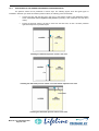
The following diagrams illustrate the behaviour of the heating and cooling devices. The percentage values
indicate the degree to which the modulating valves are opened.
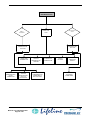
7.1.1
PROPORTIONAL CONTROL
Acts on the response speed of the system; increasing this value decreases operating error to one step, but
makes the system less stable (leads to over-sensitivity of the control system);
The control action is a function of the difference between the desired temperature or humidity value (set-point)
and the value actually measured expressed as a percentage of the proportional band.
7.1.2
PROPORTIONAL + INTEGRAL CONTROL
The control action is a function of the percentage difference on the poportional band between the desired
temperature and the calculated average temperature in the “integration time”.
In this way the control operates on the basis of an historical archive of the values assumed by the temperature
during the integration time and not just on the basis of the instantaneous temperature value. This eliminates the effect of
any sudden and temporary changes in the temperature.
7.1.3
PROPORTIONAL + INTEGRAL + DERIVATIVE CONTROL
Increases system damping and stability, thus enhances the other two control actions (with their respective
benefits) while maintaining stability. The control action is effected in accordance with the function:
Output = Kp * (e +
1
de
* ∫ e ⋅ dt + Td )
Ti
dt
where Kp represents the proprotional band, e represents the error (Input - Setpoint), i.e. the difference between the
actual value and the set-point value, Ti and Td are respectively the derivation and integration times, from the time
interval taken into consideration and the error interval. We advise that initially only Proportional Control is used, adjusting
the Kp value until satisfactory operation is obtained; at this point integral control action Ti may be introduced, while
simulatenously reducing the Kp so as not to impair system stability. Finally, on introducing derivative control action Td,
the system tends to stabilise and it will therefore be possible to increase the Kp again.
Manuale cod. 75803307C.0807
Page 31 of 60
7.1.4
SERIES H DIRECT EXPANSION AIR CONDITIONERS
•
AIR CONDITIONER WITH A SINGLE COMPRESSOR
•
AIR CONDITIONER WITH TWO COMPRESSORS
7.1.5
CHILLED WATER AIR CONDITIONER
7.1.6
COOLING CAPACITY CONTROL WITH HOT GAS INJECTION VALVE
Control of cooling capacity is achieved through an electronic hot gas injection system. Injection of hot gas
downstream of the thermostatic valve reduces cooling capacity in proportion to the request from the control system.
With this system it is possible to modulate the cooling cpacity between 50% and 100% of the rated capacity,
and obtain a corresponding reduction in power consumption. The opening of the injection valve is controlled by a 0 to
10V signal directly proportional to the percentage difference of the temperature from the set-point in relation to the
proportional band.
Manuale cod. 75803307C.0807
Page 32 of 60
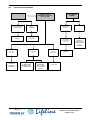
7.1.7
COOLING CAPACITY CONTROL WITH HOT GAS INJECTION VALVE AND ELECTRONIC EXPANSION
VALVE
In cases where a 50% reduction in cooling capacity is not compatible with the requirement for perfect system
control, installation of an electronic expansion valve in place of the standard thermostatic expansion valve allows
electronic control of the hot gas to reduce cooling cacpity down to just 10% of the system’s rated capacity.
The electronic expansion valve (EEV) allows control of superheating on the suction line for more efficient and
versatile operation of the refrigeration system.
Efficient, because the optimisation and stabilization of the flow of refrigerant to the evaporator increases the
overall output of the system while at the same time guaranteeing safety (less frequent tripping of the low pressure control
switch, less liquid refrigerant returning to the compressor, ...). Furthermore, if the EEV is correctly dimensioned, the use
of the floating condensation (and evaporation) pressure or at low set-point significantly increases system efficiency,
ensuring reduced power consumption and greater cooling output.
Versatile, because the EEV affords the possibility to serve refrigeration units of different cooling capacities in
widely differing operating conditions.
The following diagram shows a typical system layout. The priorities to be considered for optimal control of the
refrigeration system are a high and constant cooling capacity as well as an equally low and stable superheating.
Manuale cod. 75803307C.0807
Page 33 of 60
7.2
HUMIDITY CONTROL
Humidification control action is effected proportionally through the use of the following components:
•
•
Integrated immersed electrode humidifier
External humidifier (not supplied by TECNAIR LV)
Proportional control provides a modulating effect on the quantity of steam produced, which in the case of the
integrated humidifier ranges from to 8 to 100% of the total production, for both types of microprocessor control.
Dehumidification control is effected by a startup/opening step of the cold component with activation at the limit
of the proportional control band. Once the component has been activated, the control proceeds by regulating the cooling
capacity, in the case of the hot gas bypass or water chilled coil, up to the set-point.
The cooling capacity is never reduced below 60% of the total to allow the effect of dehumidification.
The figure illustrates the system described above:
7.2.1
SERIES H DIRECT EXPANSION AIR CONDITIONERS
•
AIR CONDITIONER WITH A SINGLE COMPRESSOR
•
AIR CONDITIONER WITH TWO COMPRESSORS
Manuale cod. 75803307C.0807
Page 34 of 60
7.2.2
CHILLED WATER AIR CONDITIONER
7.2.3
SIMULTANEOUS HUMIDIFICATION AND COOLING
Cooling the air increases its relative humidity until it reaches saturation point. It is clear that the air’s capacity to
absorb vapour depends on its relative humidity and falls to zero near saturation point. Attempting to humidify air in these
conditions, i.e. immediately after cooling, cause the vapour to condense and the consequent formation of puddles of
water inside the machine, and significant energy wastage.
For this reason, series H units are equipped with devices to interrupt humdification during operation:
•
•
Compressurized units: humidification is disabled by the specific parameter.
Chilled water unit: humidification is enabled by the specific parameter.
Should it be necessary to humidify the air at the same time as cooling it, we recommend installing an external
room humidifier.
7.2.4
DEHUMIDIFICATION LOCK
In cases where a post-heating coil (accessory) is not installed, problems of low temperature supply air may
occur during dehumidification. In this case, a software lock intervenes to prevent a significant drop in room temperature.
If the air conditioner is dehumidifying and the temperature exceeds 150% of the proportional band, the
microprocessor will inhibit dehumidification, thereby giving priority to temperature control. Dehumidification may restart,
if still required, when the temperature reaches 50% of the proportional band.
Manuale cod. 75803307C.0807
Page 35 of 60
7.3
SPECIFIC FUNCTIONS OF THE CONTROL SOFTWARE
This chapter describes certain specific functions of the control software for the series H unit.
For more detailed descriptions of the components and accessories involved in the processes, pleae refer to the
installation manual supplied with the unit.
7.3.1
NIGHT-TIME STAND-BY
This function, which is activated from the specific screen page, enables the unit to operate at reduced level
during the hours in which the room is not in use, thereby allowing energy savings.
Stand-by can be activated by daily time bands, by setting start and end times, by digital input and by remote
supervisor.
In the event of an emergency, the stand-by can be deactivated at any time to restore normal operation of the
unit.
During night-time stand-by, the unit is controlled using the folowing parameters:
TEMPERATURE CONTROL
Effected through two set-points, one high and one low,
that afford a wide window of inactivity while maintaining
the room conditions within the minimum and maximum
values.
HUMIDITY CONTROL
Effected in the same way as temperature control.
AIR FLOW
CONTROL
RATE
AND
AMBIENT
PRESSURE
Both are reduced to the minimum values that can be set.
PRESSURE CONTROL IN SUPPLY AND RETURN AIR
Controlled in the same way as air flow rate
DUCTS
TEMPERATURE/HUMIDITY ALARM CONTROL
7.3.2
Effected through thresholds linked to the various setpoints described above.
UPS CONNECTION
If the unit is connected to a UPS system via the specific digital input (see wiring diagram), it will be possible to
reduce the electrical power consumption of the unit to the minimum while still guaranteeing the sterility of the air in
the room.
During operation powered by a UPS, components with high power consumption will be disabled.
•
•
•
COMPRESSORS
IMMERSED ELECTRODE HUMIDIFIER
ELECTRICAL HEATING AND POST-HEATING COILS
All components not included in this list will continue to function normally.
Manuale cod. 75803307C.0807
Page 36 of 60
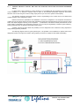
7.3.3
“H – HR” HEAT RECOVERY SYSTEMS
The heat recovery system is based on the exchange of heat between external air and the air returned from the
conditioned room. The transfer of heat between the two coils (shown in figure within the red circle) occurs via a specific
pump and an expansion valve that uses water as the heat exchange medium.
The system either adds or removes heat to/from the air entering the machine, in accordance with the preset
temperature regime.
The operation of the heat recovery system depends on the temperature values:
•
•
Text = external air temperature
Trip = return air temperature
SUMMER OPERATION: If the condition Text - Trip > ∆T is met, where ∆T is a parameter that can be set via
sotware configuration between 1°C and 5°C, and the water pump is in operation, the externa; air entering the machine is
cooled free of charge.
WINTER OPERATION: If the condition Text - Trip < ∆T is met and the water pump is in operation, the external air
entering the machine is heated free of charge.
Manuale cod. 75803307C.0807
Page 37 of 60
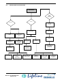
7.3.4
SUPPLY TEMPERATURE CONTROL (LIMIT)
The control of high and low supply temeparure is effected by way of various types of control in accordance with
system requirements.
High temperature can be controlled in the following ways:
•
ALARM ONLY: after the time delay, an alarm is generated
•
STOP HOT: when the alarm threshold is exceeded, the hot component is deactivated; if, after the time
delay, the temperature has still not fallen below the threshold, an alarm is generated.
•
HOT + COLD: when the alarm threshold is exceeded, the cold component is activated proportionally
to maintain the temperature below the alarm theshold. If after the time delay the temperature has still
not fallen below the threshold, an alarm is generated.
Low temperature can be controlled in the following ways:
7.3.5
•
ALARM ONLY: after the time delay, an alarm is generated
•
COLD STOP: when the alarm threshold is exceeded, the cold component is deactivated; if, after the
time delay, the temperature has still not risen above the threshold, an alarm is generated.
•
HOT + COLD: when the temperature exceeds the alarm threshold, the cold component is activated
proportionally to maintain the temperature below the alarm theshold. If after the time delay the
temperature has still not fallen below the threshold, an alarm is generated.
•
HOT + COLD: when the temperature exceeds the alarm threshold, the hot component is activated
proportionally to maintain the temperature above the alarm theshold. If after the time delay the
temperature has still not risen above the threshold, an alarm is generated.
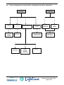
ANTIFREEZE SYSTEM
This system, enabled only when the relative temperature sensor and heating coil are installed, affords active
protection against freezing and can be operated with two different management strategies:
DAYTIME: if the antifreeze sensor, during normal operation, detects a temperature below the programmable
setpoint, the system activates the heating:
•
If after reaching 1000% the temperature is still below the alarm threshold, the fans will be switched off
and a message will appear on the main screen page. The moment the temperature rises above the
programmed threshold, the fans will be switched on again.
•
If the problem recurs more than 3 times in one hour or if the temperature remains below the alarm
threshold with the fans off for more than 10 minutes, a major alarm message will be displayed and the
unit will be shut down.
NIGHT-TIME: if the unit is tunred OFF at night, an additional protection system acts as above, opening the hot
valve so that the water circulates in the coil and thus prevent freezing.
THIS SYSTEM CAN ONLY ACTIVATED ON UNITS WITH CHILLED WATER COILS!
Manuale cod. 75803307C.0807
Page 38 of 60
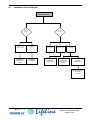
7.3.6
STERILIZATION CYCLE
This function, which can be activated from the relative menu, serves to disinfect the room, the air ducts and the
unit itself through the introduction of a sterilizing gas such as Glutaraldeide.
The operating cycle is comprised of three stages:
1)
DISTRIBUTION OF THE STERILIZING AGENT: the unit stops the exhaust fan, closing the relative
damper, and fully opens the recirculation damper. In this way the sterilizing agent reaches and saturates all
components of the aeraulic circuit. (Default 1 hour)
2)
UNIT SHUTDOWN: in this stage the unit is shut down completely so as to allow the sterilizing agent to
work. (Default 1 hour)
3)
WASHING: the unit activates both fans at 100% and shuts completely the recirculation damper.
This introduces large quantities of clean air expels all traces of the sterlizing agent. (Default 1 hour)
4)
CYCLE END: the sterilization cycle is terminated and the unit resumes normal operation.
THE CYCLE CAN ONLY BE ACTIVATED IF THE RECIRCULATION DAMPER IS INSTALLED
7.3.7
EMERGENCY OPERATION WITH UNIT IN NEGATIVE PRESSURE
This emergency procedure can be activated by holding pressed the red EMERGENCY button.
During the emergency period, the unit will work with a negative ambient pressure set-point so as to ensure that
potential contaminants are not released into the controlled environment.
The set-point, which is set automatically by the software and cannot be modified, is -15 Pa.
Once the emergency period is over, normal operating conditions can be restored by holding pressed the blue
NORMAL key.
NOTE: The state of emergency will be activated only in the case of operation with positive ambient pressure
control (OVER-PRESSURE).
The negative pressure value obtainable will depend on the controlled environment.
Manuale cod. 75803307C.0807
Page 39 of 60
8
ROUTINE AND MAJOR MAINTENANCE
WARNING!
BEFORE CARRYING OUT ANY OPERATIONS ON THE UNIT, SET THE MAIN
SWITCH TO POSITION “O”
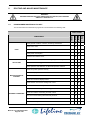
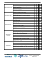
8.1
PROGRAMMED MAINTENANCE CHART
The recommended unit maintenance programme is summarised in the following chart:
FANS
Check general condition: corrosion, mountings, cleanliness
X
Check motor noise
X
Check the rotor: vibration, imbalance
X
X
Check power consumption
X
Clean the rotor and the motor
AIR FILTERS
Check the condition of the filters: Mountings, signs of damage
X
Check filters are not clogged
X
X
Check operation and calibration of differential pressure switches
Check the system operates correctly
X
X
Check the display LEDs and the alarm status
MICROPROCESSOR
CONTROL
Check the mother board connections
X
Check the control and display boards
X
Check that the unit’s sensor readings are correct
X
Check the condition of the cylinder
X
Carry out the automatic cylinder washing pocedure
X
Check the condition of the filling and drain valves
X
Carry out manual washing with limescale preventer
X
Inspect the gaskets/seals
X
Renew if necessary
X
INTERNAL HUMIDIFIER
Manuale cod. 75803307C.0807
Page 40 of 60
1 YEAR
6 MONTHS
3 MONTHS
COMPONENTS
1 MONTH
CHECK EVERY
MAINS STEAM VALVE
ELECTRICAL PANEL
Check the condition of the valve
X
Check that the valve opens and closes correctly
X
Check the condensate drain
X
Check the operating pressures
X
Check operation of the maximum humidistat
X
Check the unit is receiving power correctly
X
Check the electrical connections
X
Check the power consumptions of electrical components
X
Test safety devices
X
X
Renew protection fuses
Check circuits for leaks
X
Bleed air from circuits
X
Check circuit temperatures and pressures
X
WATER CIRCUITS
X
Check operation of the 3-way valve
Check the quantity of glycol in the circuit
X
Check the water circulates correctly
X
Check the operating temperatures and pressures
X
X
Check the condition of the compressor
REFRIGERANT
CIRCUITS
CONDENSERS
Check the condition of the liquid sightglass filter
X
Check operation of the safety devices
X
Check the calibration and operation of the control valves
X
Check the refrigerant charge level and for circuit leaks
X
Check the lubricating oil level
X
Check the condition of the remote condenser
X
Check the calibration of the remote condenser regulator
X
X
Check that the remote condenser is receiving power correctly
Check the pressure contolled valve of the water cooled condenser
X
Check the condenser water circulates correctly
X
Manuale cod. 75803307C.0807
Page 41 of 60
8.2
MAINTENANCE OF THE FANS
Fan maintenance operations must be carried out in conditions of maximum safety and always with the unit
switched off.
During maintenance, check the following:
8.3
•
Periodically check that the fan blades are clean and remove all dirt and encrusted deposits that could
affect the balance of the rotor and thus damage the bearings.
•
Check that the cooling fins of the fan motors are clean. If the fans produce any unusual noises during
operation, switch off the machine and identifty and rectify the problem, renewing the fan or the motor if
necessary.
REFRIGERATION CIRCUIT CHECKS
The refrigeration circuit does not require maintenance other than the periodic checks indicated the chapter
“Start up”.
The first of these checks is to look for leaks, as indicated by the the presence of small bubbbles visible in the
liquid viewed through the sight glass.
The cooling coil must be inspected and, if necessary, cleaned with hot soapy water using a brush with long soft
bristles. Compressed air may also be used providing that it is free of oil.
8.4
MAINTENANCE OF THE ELECTRICAL BATTERY
It is sufficient to check that the battery is clean and that the power consumption in Amps is as specified in the
technical data sheet. If the machine is equipped with a modulating electrical batttery, it is advisable to also check
occasionally that the modulator is functioning correctly.
To do this, it is sufficient to check that the machine behaves correctly during heating operation, with the relative
screen page showing a voltage of 0-10 V for the microprocessor output to the modulator. (See User manual).
8.5
MAINTENANCE OF THE ELECTRICAL PANEL
Maintenance of the electrical panel must be carried out every two months as follows:
•
Electrical and electronic components: Clean using a compressed air jet at a minimum distance of 30 cm
(to avoid danging plastic parts), pay particular attention to cooling fans and heat sinks.
•
Air inlets: The air inlets are equipped with filters that afford protection to IP54. These filter must be cleaned
or, if this is not possible, renewed.
WARNING!
Failure to clean and/or renew the air inlet filters will result in loss of IP54 protection.
TECNAIR LV shall not be liable for any damage resulting from a lack of correct maintenance of these filters.
Manuale cod. 75803307C.0807
Page 42 of 60
8.6
MAINTENANCE OF THE AIR FILTERS
On TECNAIR LV air conditioners, all air filters are equipped with differential pressure switches to monitor
pressure loss caused by clogging. The microprocessor signals when the measured pressure difference exceeds the set
value. To change the trip setting of a differential pressure switch, simply unscrew the cover and turn the setting dial to the
desired pressure differential value.
FILTER TYPE
POSITION
VALUE [Pa]
F5 filter
Air return
250
F6 filter
External air
300
F9 filter
Supply air
400
The filters must be renewed every time the relative clogged filter alarm is generated. To change a filter, switch
off the unit, open the front panels and remove the filter. The panels to be opened are exclusively those indicated in the
drawing supplied with the machine. They are to be opened using the key provided.
WARNING!
Used filters are to be disposed of as SPECIAL WASTE.
Under no circumstances may the air conditioners be operated without the filters.
To ensure the efficiency of the filters, it is necessary to install the 15x3 mm seal.
We also recommend installation of an external air pre-filtration system with an efficiency of at least G3 to avoid
frequent clogging of the F6 filters and thus reduce the system operating costs.
Manuale cod. 75803307C.0807
Page 43 of 60
9
WASHING, CLEANING AND DISINFECTION
WARNING!
BEFORE CARRYING OUT ANY OPERATIONS ON THE UNIT, SET THE MAIN
SWITCH TO POSITION “O”
9.1
WARNINGS
1)
Before proceeding with any cleaning operations, it is essential to read the following information and make sure
that you have fully understood it.
2)
All cleaning operations must be carried out in accordance with the instructions given here below, as incorrect
procedures could be seriously damage the equipment and/or be hazardous for the operator.
3)
TECNAIR LV air conditioners contain rotating parts, live parts and pressurised parts. To avoid all risks, before
opening the unit for any cleaning operations, it is essential to proceed as follows:
•
•
•
9.2
Make sure that the unit has been switched off.
Make sure that all moving parts (compressor in the drive compartment, exhaust fan and supply fan)
are stationary (i.e. have have stopped rotating).
Make sure all electrical power supply lines to the appliance are disconnected.
4)
The following instructions apply exclusively to the cleaning of the air conditioner. It is assumed that the
maintenance, cleaning and/or disinfection of system components (inside the air ducts, air vents and/or diffusers,
germicidal lamps, humidifier water supply treatment systems, condensate drainage systems, ect.) are carried
out at the intervals and in the manner indicated by the respective manufacturers and by the system installer.
5)
The cleaning, washing and disinfection of the air conditioner alone, even when carried out in accordance with
the instructions given in this manual, are not in themselves sufficient to ensure the necessary aseptic conditions
in the entire system TECNAIR LV series “H” air conditioners, although equipped with internal filters, are
designed for climate control, not to ensure the sterility of the environment. To guarantee the necessary degree
of environmental sterility, the installer must install under their own responsibility and at their own expense
absolute filters at each air vent or diffuser in the room.
6)
The cleaning of the series “H” air conditioners used for the climate control of operating theatres must be carried
out by specially trained personnel of the hospital maintenance department to prevent bacterial contamination of
the air conditioners. Only in this way is it possible to safeguard the helath of all cleaning operatives, medical
personnel and patients who enter the rooms in which the air conditoners are operated.
CLOTHING TO BE WORN DURING CLEANING OPERATIONS
Unless otherwise indicated by the doctor in charge of the surgical room, all cleaning personnel, in order to
safeguard their own health as well as ensure successful result of the operations undertaken, must wear:
•
•
•
•
•
Clean overalls
Eye protection
Latex rubber gloves (during cleaning and disinfection of the operating compartments, gloves must be
changed as soon as they become dirty).
Antiseptic mask
Shoe covers
On completion of the cleaning operations, all the protective clothing worn must be disposed of as infected
waste, except the overalls which may be used after washing and disinfection.
Manuale cod. 75803307C.0807
Page 44 of 60
9.3
CLEANING SYSTEMS
As the air conditioners contain electrical components (electric motors, terminal blocks, sensors, etc.) that could
be damaged by high pressure water jets or high temperatures, and a refriegeration system that must not be subjcted to
high pressures, the use of steam or pressurised water jets for cleaning operations is strictly prohibited.
The water and disinfectant solution used to disinfect the appliance must only be used in the from of a nebulised
spray. Use a manually operated sprayer to obtain a nebulised spray for air conditioner cleaning.
For washing and disinfection operations, use exclusively a 4% ammonium chloride and water solution (or a
chemically equivalent commercial solution) applied using a manual sprayer.
Every air conditioner can be divided into three zones:
9.4
1)
TECHNICAL COMPARTMENT: the part of the air conditioner containing the control systems and the
compressors. In this zone there is no air circulation and therefore disinfection is not normally required.
The technical compartment must be cleaned using a vacuum cleaner, with a renewable paper filter and a soft
brush installed on the suction nozzle. Unless otherwise indicated by the doctor in charge of the room, used
vacuum cleaner filters do not necessarily have to be disposed of as contaminated waste.
2)
OPERATING COMPARTMENTS: the zone of the air conditioner containing parts where air treatment takes
place. This zone is subject to a flow of external air to the operating room after suitable treatment, and to the flow
of air returning from the operating room and expelled into the environment. Notwithstanding the filtration
systems present in the air suction, retunn and distribution system and in the air conditioner itself, this zone may
harbour bacteria which could proliferate when the unit is idle and thus create a health hazard when the unit is
next used. These compartments must be washed and disinfected at least once a month or each time a surgical
operation is performed that carries a risk of spreading harmful bacteria. However, as the frequency and manner
in which operating rooms are used can vary greatly, the responsibility for deciding when washing and
disinfection of these compartments is necessary rests exclusively with the person in charge of the medical
department. Proceed as follows:
•
Remove the air filters before proceeding
•
Remove the pre-heating water coil (if present) as otherwise it could limit the effectivenss of any
cleaning of the cold coil.
•
Wash the cold coil with sterilizing solution spray.
•
After re-installing the pre-heating coil, wash it usimg the same method.
•
Wash the heat recovery coils (if present).
•
Wash thoroughly the walls of the operating compartments, including those housing the fans.
•
Allow the unit to dry before refitting the filters.
3)
EXTERIOR OF THE AIR CONDITIONER: the exterior of the unit is made from enamelled sheet steel and
should only be cleaned in accordance with the criteria and the procedures specifically indicated in this manual.
If the air conditioner is installed inside the operating theatre or in a communicating room (anaesthetic room,
wake-up room, post-operative observation room, etc.), its exterior must be cleaned and disinfected at the same
time as its operating compartments, unless otherwise indicated by the ward manager. If instead the unit is
installed in a technical room not in communication with the operating theatre, it is sufficient to clean the exterior
when traces of dust or grease are apparent
DISPOSAL OF USED CLEANING MATERIALS
The cleaning of the air conditioners produces both solid (old filters, operator’s clothing, worn drivebelts, etc.) and
liquid waste materials (washing fluid residue and water used for rinsing).
The solid waste materials should be put into sealed containers and disposed of along with the contaminated
hospital waste.
Liquid waste can be allowed to flow out through the drain outlets of machine’s condensate collection trays
These trays are to be connected to the hospital's waste disposal system for hazardous liquid waste
Manuale cod. 75803307C.0807
Page 45 of 60
10
FAULT DIAGNOSIS
WARNING!
BEFORE CARRYING OUT ANY OPERATIONS ON THE UNIT, SET THE MAIN
SWITCH TO POSITION “O”
This chapter contains information to assist the operator in tracing any faults that may arise with the machine
Starting from a description of the nature of the problem, we provide indications on the probable causes and possible
remedies. The description of the causes is generic and therefore takes into consideration the most complete versions of
the machine; it is the task of the operator to determine which of the information provided applies to the machine in
question.
All servicing and repair of the machine must be carried out by qualified personnel only.
We strongly recommend that you do not attempt any operations on the machine unless you have a good
understanding of its operating principles.
Key to the fault diagnosis diagram:
Manuale cod. 75803307C.0807
Page 46 of 60
10.1
MALFUNCTION OF THE FAN CONTROL INVERTER.
The following table lists the fault codes, the causes and the remedies for problems regarding fan control
inverters.
CODE
1
FAULT
Overcurrent
POSSIBLE CAUSE
REMEDY
The inverter has detected that the current
at the outlet terminals is too high (>4*IH)
Check the load
Sudden increase in load
Check the size of the motor
Short-circuit in motor wiring
Check the wiring
Unsuitable motor
The voltage of the intermediate DC circuit
has exceeded the preset limits.
2
Over-voltage
Acceleration time too short
Increase the deceleration time.
High voltage surges in the supply line
3
Earth fault
Current measurement has determined that
sum of the motor phase currents is
not zero.
Check the motor wiring and the motor.
Faulty insulation of the wiring or the motor.
8
System fault
Component fault
Malfunction
The voltage of the intermediate DC circuit is
below the preset voltage limits.
9
Under-voltage
Most probable cause: supply voltage
too low.
Internal inverter fault.
11
Ouput phase
supervision
13
Inverter undertemperature
Current measurement has determined that
there is no current on one of the motor
phases.
Remedy the fault and restart.
If the fault recurs, contact our assistance
centre
In the case of temporary interruption of the
power supply, reset the fault and restart the
inverter. Check the power supply voltage. If
OK, the problem is due to an internal fault
Contact our assistance service.
Check the motor wiring and the motor.
The temperature of the heat sink is
below –10°C.
The temperature of the heat sink is greater
than 90°C.
Check that the quantity and flow rate of the
cooling air is OK. Check that there is no dust
buildup on the heat sink. Check the ambient
temperature. Check that the commutation
frequency is not too high relative to the
ambient temperature and the load on the
motor.
14
Inverter overtemperature
15
Motor stalled
The motor stall protection has tripped.
Check the motor.
16
Motor overtemperature
The motor temperature model of the
inverter has detected overheating of the
motor. The motor is overloaded.
Reduce the load on the motor. If the motor is
not overloaded, check the temperature
model parameters.
17
22
Motor
underload
Checksum error
EEPROM
The over-temperature alarm trips when the
heat sink temperature rises above 85°C.
The motor underload protection has
tripped.
Failed parameters recovery
Malfunction
Contact our assistance service.
Component fault
Manuale cod. 75803307C.0807
Page 47 of 60
CODE
FAULT
24
Counter fault
25
Watchdog faulty
POSSIBLE CAUSE
The value displayed on the counter is
incorrect.
Malfunction
Component fault
29
Thermistor fault
The thermistor input on the optional board
has detected an increase in the motor
temperature.
34
Internal
communication
bus
Environmental interference or defective
hardware.
41
IGBT
temperature
52
Panel
communication
fault
Manuale cod. 75803307C.0807
Page 48 of 60
REMEDY
The inverter IGBT bridge has detected an
excessive overload current of brief duration.
The connection between the control panel
and the inverter is interrupted.
Reset the fault and restart.
If the fault recurs, contact our assistance
centre
Check the load and the cooling system.
Check the thermistor connection (if the
thermistor input of the optional board is not
used it must be short-circuited).
Reset the alarm and restart. If this alarm
code reappears, contact our assistance
service.
Check the load
Check the size of the motor
Check the panel connection.
10.2
DIRECT EXPANSION AIR CONDITIONERS – REFRIGERATION CIRCUIT PROBLEMS
LOW PRESSURE
BLOCKAGE
REFRIGERATING
CIRCUIT
DISCHARGED
THERMOSTATIC
VALVE FAULTY
SEARCH FOR
THE LEAK
THEN
RESTORE
RENEW THE
BELLOWS
CLEAN THE
AIR FILTERS
LOW AIR FLOW IN
THE EVAPORATOR
NO
COMPRESSION
LOW
CONDENSATION
PRESSURE
CHECK THE
CONDENSATION
CONTROL SYSTEM
CHECK AIR
CIRCUIT
RESTORE
ORIGINAL
CONDITIONS
MECHANICAL
BREAKAGE
VALVES
BROKEN
DISCONNECT
COMPRESSOR
AND RENEW
CHECK FAN
SETTING
Manuale cod. 75803307C.0807
Page 49 of 60
HIGH
PRESSURE
BLOCKAGE
AIR
COND.
AIR FLOW RATE TO
THE CONDENSER
TOO LOW
CHECK FOR ANY
OBSTRUCTIONS
ON THE COIL
WATER
COND.
AIR INLET
TEMPERATURE
TOO HIGH
MEASURE THE
AIR
TEMPERATURE
REFRIGERATING
CIRCUIT CHARGED
TOO MUCH
FAN DOESN’T
WORK
ELIMINATE ANY
RECIRCULATION
OF THE
DISCHARGED AIR
CHECK EFFICIENCY
OF CONDENSATION
CONTROL SYSTEM
CHECK THERMAL
CIRCUIT BREAKERS
AND POWER DRAW
CHECK AND
BRING BACK
WITHIN THE
LIMITS
CLEAN
CONDENSATING
COIL
NO WATER
CHECK THE PUMPS
AND SHUT-OFFS OF
THE HYDRAULIC
CIRCUIT
Manuale cod. 75803307C.0807
Page 50 of 60
PRESSURE
CONTROLLED
VALVE FAULTY
CHECK OPERATION
AND SETTINGS
REFRIGERATING
CIRCUIT CHARGED
TOO MUCH
CONDENSER
DIRTY
CHECK AND BRING
BACK WITHIN THE
LIMITS
CLEAN
INLET WATER
TEMPERATURE
TOO HIGH
CHECK AND
RESTORE THE
ORIGINAL
CONDITIONS
10.3
CHILLED WATER AIR CONDITIONERS – WATER CIRCUIT PROBLEMS
NO CHILLING
AIR IN THE
CIRCUIT
CHECK AND
DISCHARGE THE
AIR IN THE
CIRCUIT
WATER
TEMPERATURE
TOO HIGH AT THE
EVAPORATOR
OUTLET
THREE-WAY
VALVE FAILS TO
OPEN
CHECK THE CHILLER AND
BRING THE TEMPERATURE
BACK TO DESIGN CONDITIONS
CHECK THE
ELECTRONIC CARD
CHECK THE
SERVO-MOTOR
WORKS PROPERLY
CHECK THERE IS NO
JAMMING IN THE
OPENING SYSTEM
Manuale cod. 75803307C.0807
Page 51 of 60
10.4
HEATING SECTION PROBLEMS
NO HEATING
POST
WITH
HOT GAS
WATER
ELECTRICAL
NO POST
HEATING
NO SERVOCONTROL
OPERATION
NO HEATING
CIRCUIT BREAKER
TRIPS
SAFETY
THERMOSTAT
TRIPS
CHECK SUPPLY
AND MODULATING
SIGNAL
HEATING ELEMENT
SHORTED OR TO
GROUND
HIGH
TEMPERATURE
DUE TO REDUCED
AIR FLOW
VALVE FAILS TO
OPEN
CHECK SERVOCONTROL
OPERATION
CHECK AND
BRING BACK
TO DESIGN
CONDITIONS
DISCONNECT
AND RENEW
CLEAN THE
AIR FILTERS
WATER
TEMPERATURE
TOO LOW
CHECK AND
BRING BACK TO
DESIGN
CONDITIONS
Manuale cod. 75803307C.0807
Page 52 of 60
CHECK FAN
OPERATION AND
CONNECTIONS
CHECK SERVOMOTOR
OPERATION
CHECK
SUPPLY AND
MODULATING
SIGNAL
CHECK THERE IS
NO JAMMING IN
THE OPENING
SYSTEM
10.5
DEHUMIDIFICATION PROBLEMS
NO
DEHUMIDIFICATION
DIRECT
EXPANS.
COMPRESSOR
FAILS TO START
CHECK
SIGNALS ON
ELECTRONIC
CARD
REFRIG.
WATER
HIGH AIR FLOW
RATE
BRING BACK
TO DESIGN
CONDITIONS
HIGH AIR
FLOW RATE
BRING BACK
TO DESIGN
CONDITIONS
HIGH WATER
TEMPERATURE
CHECK
SUPPLY ON
ELECTRONIC
CARD
VALVE FAILS
TO OPEN
CHECK SERVOMOTOR
OPERATION
REMOVE ANY
JAMMING IN THE
CLOSING
SYSTEM
Manuale cod. 75803307C.0807
Page 53 of 60
EXCESSIVE
DEHUMIDIFICATION
AIR FLOW
RATE TOO
LOW
DIRECT
EXPANSION
REFRIGERATED
WATER
WATER
TEMPERATURE
TOO LOW
EVAPORATION
TEMPERATURE
TOO LOW
CHECK FOR
JAMMED FAN
CHECK
THERMOSTATIC
VALVE
OPERATION
CHECK
WHETHER
REFRIGERATING
CIRCUIT IS
DISCHARGED
Manuale cod. 75803307C.0807
Page 54 of 60
CHECK FAN
CIRCUIT
BREAKER HAS
TRIPPED
CHECK THAT
CONDENSATION
PRESSURE IS
NOT TOO LOW
CHECK FAN
ELECTRICAL
CONNECTION
CLEAN
FILTERS
CHECK AIR
CIRCUIT
BRING BACK
TO DESIGN
CONDITIONS
10.6
VENTILATION PROBLEMS
NO AIR FLOW
THERMAL CIRCUIT
BREAKER TRIPPED DUE
TO HIGH DRAW
FLOW SWITCH
JAMMED
NO AIR
OPERATION WITH
PANELS OPEN
CLOSE THE
PANELS
LOW SUPPLY
VOLTAGE
MEASURE
VOLTAGE IF
CORRECT
DIRTY
FILTERS
MECHANICAL
BREAKAGE
CLEAN THE
FILTERS
CHECK
MECHANISM
OPERATION AND
SETTING
HIGH AIR FLOW
RATE
REDUCE SPEED
BY MODIFYING
THE ELECTRICAL
CONNECTION
HIGH AIR
TEMPERATURE
CREATE
ADDITIONAL
HEAD LOSSES
IN THE AIR
CIRCUIT
CHECK
AERAULIC
CIRCUIT AND
DIRECTION OF
FAN
ROTATION
RENEW IT
AIR FLOW RATE
TOO LOW
Manuale cod. 75803307C.0807
Page 55 of 60
11
GLOSSARY
•
Dead band – neutral band: defines a very narrow temperature range between the set-point and the
proportional band within which the control devices are not operated.
•
Default: this term is used to describe the values (e.g. set-point and proportional band values) that will be
automatically applied by the system if the operator fails to set them.
•
Modulating valve: The modulating valve is controlled by a signal with voltage varying from 0 to 10 V.
•
Proportional band: defines a temperature range of just a few degrees starting from the setpoint,
within which the system operates the control devices.
•
Ramp: the operating range of a modulating valve from 0% to 100%
•
Range: range of values that may be assumed by a parameter.
•
Return – Suction: air from the controlled environment returned to the air conditioner.
•
Screen page: a page displayed on the screen.
•
Set-point: defines the temperature (or humidity) value to which the control system is set; the system
activates the hot or cold control devices until the temperature (or humidity) in the controlled environment
matches the set-point.
•
Step: defines an area of the proportional band (of temperature or humidity) within which a device is
switched on and at the same time defines the values at which the device is switched on and off.
•
Supply: the air delivered to the room by the air conditioner.
Manuale cod. 75803307C.0807
Page 56 of 60
12
NOTES
Manuale cod. 75803307C.0807
Page 57 of 60
Manuale cod. 75803307C.0807
Page 58 of 60
Manuale cod. 75803307C.0807
Page 59 of 60
Manuale cod. 75803307C.0807
Page 60 of 60