1
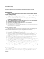
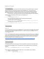
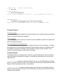
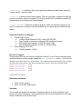
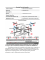
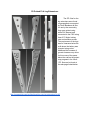
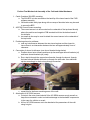
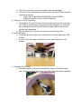
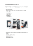
User Manual Autonomous Quadcopter Platform Hardware Setup WARNING: Experience with flying Remotely Controlled QuadCopter is required. Binding Procedure Binding is required the first time the craft is used with a new transmitter. It is done using the following procedure. 1. To place Rx into binding mode, pace a wire jumper across PCB board “Term 8” Pins 1 & 4. This will force the Rx into binding mode. 2. Connect the 4Cell 4aH LiPo battery to the craft using the yellow xt60 battery connectors at the bottom of the craft. 3. Wait for the orange “Bind Led” on the Radio Receiver (Rx) to begin flashing rapidly. 4. Follow binding procedure on DSM2 Tx of choice. 5. Bind LED will stop flashing and burn solid once Tx & Rx are bound. 6. Remove jumper from PCB“Term 8”. 7. Power Cycle Craft to confirm bind. Bind LED will turn on solid when communication between Tx and Rx is established. Prepping the Craft for Flight Before the flying craft ensure that it is in good flying condition. Visually inspect the Craft for wear and disconnected wires, repair using attached documentation. 1. Power on the DSM2 Compatible Transmitter (Tx). 2. Place the “Channel 5” (Often referred to as the Gear Switch) into “Position 0”. The setting with a 1000uS on time for Channel 5. This places the craft in direct user control. 3. Install the 4Cell 4Ah LiPo battery on to the craft, using the included Velcro strip. 4. Plug the yellow xt60 battery connector to the power lead of the craft. 5. The orange “Bind Led” on the Radio Receiver (Rx) will change to solid orange once a radio link between the Tx & Rx is established. 6. Before flying, the CC3D must be armed. This is done by giving a full Throttle down and a full Yaw CCW command on the left Tx stick. Hold this position and observe blue status LED on CC3D. Unit will flash rapidly for 5 seconds and go dark. Unit is now armed, and will respond immediately to Tx stick inputs. 7. To disarm the craft, giving a full Throttle down and full Yaw CW command on the left Tx stick. Additionally, unit will self disarm after 30 seconds of nonactivity from the Tx. Programming the CC3D The CC3D is responsible for leveling the craft. Before it can do that, it must first be configured to talk with the hardware. This is done using the OpenPilot Ground Control Software. Download the OpenPilot GCS software version 15.02.01 from https://wiki.openpilot.org/display/WIKI/OpenPilot+Downloads . Install the program using the default location and settings. Start the OpenPilot GCS program, at the welcome screen connect the CC3D to the computer using the mini USB port. On the welcome screen, use the vehicle setup wizard to configure the craft’s hardware settings. This will define the motor outputs and the Transmitter inputs. One important point where the P15230 Craft differs from the configuration wizard is in the Input settings. The current version of the OpenPilot GCS used pin 8 for the PPM input. The Craft is configured to use pin 3. To change this setting navigate to the “Configure pane” on the bottom of the screen. Click the “Hardware Button” at the top left. From there click the input drop down and select “PPM+NoOneShot”. Click the save button on the bottom right of the page to save the configuration. IMPORTANT, The OpenPilot program and the CC3D must be restarted to take effect. From here the Transmitter may be configured using the “Transmitter Setup Wizard”. This is located on the “Configure/Input” pane. Click the “Start Transmitter Startup Wizard” button, when complete click save on the bottom right hand corner of the page. Additional References Here is some additional information pertaining to flying an RC QuadCopter. This information links to 3rd party sites. This material is linked to often by the RC community, but is unvetted by the MSD Team. http://myfirstdrone.com/howtoflyaquadcopter/ Tutorial on Flight Introduction to Controls https://www.youtube.com/watch?v=P3E2pQnEDRI Tutorial on Flight Video (Part 1) https://vimeo.com/90043790 Tutorial on Flight Video (Part 2) http://blog.oscarliang.net/quadcoptertutorialhowtoflydrone/ Additional Tutorial http://www.uavcoach.com/howtoflyaquadcopterguide/ Detailed review on RC Terminology Software Setup Starting Program At start the default program will run once the start push button is pressed. This will run the compiled program ‘lmnoCopter’ located in the mainProg folder on the Raspberry Pi. The teensy will automatically run its program at power on. When a program is ran from the start button press all console output is directed to a log file timestamped and located in the logs folder within the mainProg folder. Starting the Craft With the crafts onboard computers started the user may use the transmitter to toggle between autonomous and user controlled operation. For safety purposes, the Teensy is unable to arm the CC3D, thus the CC3D must be armed by the user. Inorder to do this the craft is first placed into Direct Control Mode. This is done by placing Channel 5 into POS0. With the craft under direct user control, the user may now arm the CC3D. This procedure is covered in steps 6 & 7 of “Prepping the Craft for Flight”. Notes about direct user control. In Channel 5 :POS0 the unit is programmed for direct user control and self stabilization. Stick inputs correspond to displacement angles. that is 0% stick movement corresponds to 0° displacement, and 100% stick movement corresponds to 11° displacement. All controls are limited to 11° from level. Notes about autonomous control. In Channel 5: POS1 the unit is programmed for autonomous control. Commands from the onboard computers are passed to the CC3D. a. Note: POS1 initiates Auto Hover Mode with Rev03 Firmware. Environment Setup on New Hardware When starting with a blank teensy and Raspberry pi, the programs should be loaded and installed as follows. Additionally the Teensy program must be modified when binding to a new Tx. Teensy Program Developing Environment Download the Arduino Sketch environment from arduino.cc. Install version 1.6.4. Install the Teensyduino version 1.23 addon from https://www.pjrc.com/teensy/td_download.html . Follow installation guide and add All libraries when given the option. Add Arduino Libraries Within the Arduino Sketch environment the jmPID and sharedi2cCom libraries should be previously installed. This is done by adding the jmPID and sharedi2cCom folders into the PATH_TO_ARDUINO_WORKSPACE/Arduino/libraries folder. Additionally DEFINED_VALUES.h must be placed into the PATH_TO_CODE/TeensyRev04 folder. In order for Arduino sketch to recognize these libraries the IDE should be restarted. Load Program onto Teensy Within the Arduino Sketch environment press the verify button. The compiler will compile the program and assure that all libraries and include files are in the proper place. When the program compiles successfully, click the upload button within the Arduino Sketch environment. the TeensyDuino add on will pop up. At this time press the black button located on the Teensy Development board. The TeensyDuino will show a progress bar as it uploads the new code to the Teensy. At its completion the TeensyDunio addon will say Upload Complete. New Tx Setup with the Teensy The Teensy microcontroller is configured to emulate the user's Tx. Each Tx has its own offsets and errors around neutral. The Teesny must be configured to emulate these offsets and errors inorder for the CC3D tuning to work with the craft. These offsets may be determined using the following method. Download the OpenPilot GCS software version 15.02.01 from https://wiki.openpilot.org/display/WIKI/OpenPilot+Downloads . Install the program using the default location and settings. Start the OpenPilot GCS program, at the welcome screen connect the CC3D to the computer using the mini USB port. Click the Configure Tab at the bottom left hand corner of the window. This will bring up the configuration page. Click the input tab at the top left of the window to bring up a live telemetry of the current inputs. The neutral column will contain the offset value. To compute this offset, for throttle subtract 1000 from the neutral value. Here it is 100. For the Roll, Pitch, and Yaw channels subtract 1500 from the neutral value. Here it is 15, 19, 19. CC3D Program Installing the Program The CC3D is configured using the OpenPilot Ground Control Software. Download the OpenPilot GCS software version 15.02.01 from https://wiki.openpilot.org/display/WIKI/OpenPilot+Downloads . Install the program using the default location and settings. Reloading the P15230 PID Settings The CC3D uses PID control law to level and stabilize the craft in flight. The craft has previously been tuned by the team for stable flight. These values are already loaded on the CC3D but may be reloaded in the following way. Start the OpenPilot GCS program, at the welcome screen connect the CC3D to the computer using the miniUSB port. Click the system tab at the bottom of the window. Click File/Import UAV Setting. From the file browser window select the path to the P15230_CC3D File. Click Select, to load the settings onto the CC3D. NOTE: This will override the Tx calibration, and will require calibrating. Calibrating the Tx Calibration of the Tx can be completed using the Transmitter Setup Wizard. This software will walk the user through calibrating the CC3D to their particular transmitter. This will recompute new maximum and minimum values. Access the Transmitter Setup Wizard by clicking the configuration tab at the bottom of the screen. Click the “Start Transmitter Setup Wizard” button. When the program is complete, Click the Save button at the bottom right of the screen. R aspberry Pi Program Connecting to the Pi Most file transfers onto and from the pi was done via Secure Shell login on a shared network between the connecting computer and the Raspberry Pi. This can be done in Windows environments using shell clients such as Putty or through interfaces provided in MATLab and Simulink. In a Unix Environment, this can be done via the Terminal prompt. For this section, connection was done via a Unix terminal prompt with host computer enabling shared ethernet as a DHCP host for the Raspberry Pi. To login: $ ssh PIUSERNAME@ASSIGNED_IP You now should have access to the Pi’s terminal command prompt. To transfer files via secure shell to Pi: $ scp path_to_file/file PIUSERNAME@ASSIGNED_IP:path_to_pi_file/file To transfer files via secure shell from Pi: $ scp PIUSERNAME@ASSIGNED_IP:path_to_pi_file/file path_to_file/file Setup Pi LIbraries Enable I2C If you can’t find the I2C device on the Raspberry Pi, it may need to be manually removed from the blacklist that Raspbian supplied with its OS. To check if the driver is enabled on the Pi’s command prompt enter: $ ls /dev/ If “i2c1” is not listed check for other i2c named devices. If there is an I2C device of a different name, this name with have to be edited from the file (device handler) used to the openi2cBus function in the masteri2cCom source file. If no i2c device is listen it will have to be enabled. Follow the Adafruit tutorial to enable this device as https://learn.adafruit.com/adafruitsraspberrypilesson4gpiosetup/configuringi2c . Add Source Files to Pi Copy startup scripts The startup scripts that run the program from the pushbutton press should be copied to the home folder of the logged in user. This can be done via the command from your host Unix machine: $scp start PIUSERNAME@ASSIGNED_IP:/home/PIUSERNAME/ If the crontab isn’t modified to reference these files, it can be added to the crontab by; 1. making a cron log directory: $ cd #go to home directory $ mkdir logs #create log directory 2. open cron: $ sudo crontab e 3. edit to run script at reboot: @reboot sh /home/PIUSERNAME/start/launcher.sh > /home/PIUSERNAME/logs/cronlog 2>&1 Copy Main Program To transfer the main programs source code use the command: $scp mainProg PIUSERNAME@ASSIGNED_IP:/home/PIUSERNAME/c_code/ Changing Program Programs to Build From the Makefile provided in the mainProg folder many compile options are identified mostly for testing during system integration. Adding Programs To add programs to the source make sure that the Makefile is modified to compile and link those programs properly. Referencing Programs For Button Start The startup script runs the program compiled under the name ‘lmnoCopter’, to change the program that runs at the button press either the executable created in the Makefile could be modified to rename its executable, the executable could be manually renamed, or the reference in the lmnoCopter.sh script could be changed. Compile Program The Makefile makes recompiling easy. On the Pi’s command prompt just run the command make and whatever component to compile. The compile time can take up to 2 minutes from original source. $ make comlink : creates the main file that allows the user to send PPM packets of throttle, pitch, roll, and yaw values from the Pi to the Teensy slave device which will generate the PPM signals to send to the flight controller on the platform. $ make test_sonar : creates the comlink program with the option of requesting incoming data from the teensy which includes the four connected sonar sensors as well as current and voltage sensing readings. $ make test_acc : creates the test_acc program that displays all reading from the IMU in 10 polls spaced 1 second a piece. $ make all : creates the lmnoCopter program. This is the program in progress for applying autonomy for indoor waypoint navigation. Currently the craft has no localization method and forward and hover commands are unimplemented. $ make avoidance : creates the avoidance program, which is a following program for the craft. The craft tries to maintain a constant distance from a sensed object on the back sonar sensor. Potential Add-Ons to Program 1. 2. Finalize Flight Control a. Tuning of Flight Controls (CC3D, Teensy PID, RPi PID) b. Face Tracking or Alternative Following UAS with distance locking c. WiFi Positioning Integration To UAS For Indoor Flight d. GPS Positioning Integration To UAS For Outdoor Flight Indoor Mapping (2D or 3D) a. LIDAR Integration To UAS Errors In Program Though status LEDs are not currently configured for the RPi, the I2C communications status came be read by the main program reading the uint8_ti2cComStatus variable. A bit within that variable serves as a flag for the teensy slave , the compass and accelerometer slave sensors, the barometer slave sensor, and the gyroscope slave sensor. Each bit is defined below: # define COMSTATUS_COM_ACC # define COMSTATUS_BARO # define COMSTATUS_GYRO # define COMSTATUS_TEENSY (0x01) (0x02) (0x04) (0x08) Localization Program Necessary Hardware 1. Three 2.4 GHz routers 2. One 2.4 GHz WiFi USB receiver Software The software was designed to be used in conjunction with the A* search algorithm’s grid layout of an area of known size. There must be three WiFi routers at ground level, each with known coordinates on the A*search grid. The first part of the code takes the recorded signal strength of a router and calculates a distance based on the formula found here: http://stackoverflow.com/questions/11217674/howtocalculatedistancefromwifiroute rusingsignalstrength The 27.55 term is a constant based on both the units of the frequency of the signal and the units of the distance from the router. In this case, the frequency is measured in megahertz and the distance in meters, so 27.55 is used. More information on this constant can be found here: http://en.wikipedia.org/wiki/Freespace_path_loss#Freespace_path_loss_in_decibels The main function first tries to connect to each router (referred to as A, B, and C) in order based on a counter variable that increments once all calculations are finished for the currently connected router. In order to connect to the routers, the proper SSID and password must be entered in the code itself, replacing the terms “Router A/B/C” and “wifipassword” with the appropriate values. Once connected to a router, the frequency of the signal, and the signal strength at the craft’s location. Once it has these parameters, the calculations from above are run to convert the signal strength into a distance. This process is repeated until all three routers have a recorded distance. After all three distances have been recorded, these are used in geometrybased equations to pinpoint the craft’s <x,y,z> coordinates on the A* search grid. The process is then repeated. For best results, place Router A at <0,0,0>, Router B at an adjacent corner, and Router C on the far side, halfway between the endpoints. Issues First, WifI has been found to be unreliable for this purpose. NFC or bluetooth hotspots with dedicated connections to the Pi would be preferable. This will eliminate the need to cycle through connections. The method of obtaining the distance from each hotspot will need to be changed to reflect the change in hardware. Using WiFi, the 2.4GHz routers are not the most optimal choice. 5GHz routers would be much more preferable as the signal strength changes more noticeably with distance, allowing for more accurate distance calculations than the current setup. If the included WiFi receiver is used, there will not be a need to replace it for a 5GHz compatible model, as this is already supported. Mechanical Assembly ➢ ➢ ➢ ➢ ➢ ➢ ➢ ➢ ➢ ➢ ➢ ➢ ➢ ➢ ➢ ➢ ➢ ➢ ➢ ➢ ➢ Mechanical Bill of Materials: 10001 4mm0.70 Metric Nylon Lock Nuts (x12) 10002 4mm0.70 x 20mm PanHead Metric Machine Screws (x12) 10003 Velcro 10004 ZipTies (x8) 11001 Rotor Shroud EPS Foam 19''x19*x14'' 11002 Shroud Hold down upper brace (x4) 11003 Shroud Hold down lower brace (x4) 11004 3D printed leg extensions pt 1 (x4) 11005 3D printed leg extensions pt 2 (x4) 12005 DJI F450 Quad ARF Kit ○ Kit contains individual components/assembly documentation ■ See F450 Kit assembly below Relevant Electrical Hardware Bill of Materials: 20006 PCB Board 22000 Castle Creations 20A BEC 22002 HCSR04 (x4) 22004 GY80 22006 Raspberry Pi NOIR Camera 22009 ACS709 Current Sensor 75A to +75A 22010 CC3D 22011 OrangeRx R615X DSM2 22014 Turnegy NanoTech 4000mAH 30000 PJRC Teensy 30001 Raspberry Pi 2 F450 Kit Assembly: Assembly Materials: *** NOTE, MOTORS AND ESCs USED WERE FROM DJI E300 TUNED PROPULSION KIT WHICH INCLUDES 2212 DJI MOTORS, 30A ESCs AND 9.4x4.3” PROPELLERS.*** Required Tools for Assembly: Assembly Diagram: ***TAKE CARE WHEN THREADING M3x8 SCREWS INTO 2212 DJI MOTORS SO AS TO NOT STRIP THE INTERIOR THREADS ON THE MOTOR ASSEMBLIES*** This platform was chosen for its simplistic modular design where components are easily replaced if broken or found defective. It fit the original price range given for the purchase of a quadcopter platform. The E300 propulsion package was ordered for the additional thrust and well tuned ESC, motor and propeller pairing. The E300 configuration is rated for 600grams/axis maximum thrust output. 3D Printed PLA Leg Extensions: The STL files for the leg extensions were found on garagepilots.com posted by Gavin Bendtsen as files for use by the community, they were printed using white PLA filament and connected to the F450 using 4mm0.70 Nylon locking nuts and machine screws. The requirement of the legs was for clearance below the craft where the battery was mounted using velcro. Additional this increase of ground clearance may allow for future use of the space below the craft as the project may progress in the future. STL files can be found at the web page linked below. http://garagepilots.com/profiles/blogs/thenewlegextensionsfordji 1. 2. 3. 4. Further Final Mechanical Assembly of the Craft and Added Hardware: Castle Creations 20A BEC mounting: a. The 20A BEC is to be mounted on the back lip of the lower board of the F450 airframe assembly b. 3M double sided sticky tape along with one wrap of electrical wire may be used to secure the BEC. ASC709 Current Sensor mounting: a. The current sensor is to be mounted on the underside of the top board directly above the positive and negative PCB terminals built into the bottom board of the airframe. b. two small zip ties may be used to attach the current sensor to the underside of the top board. Positioning shroud on airframe: a. note any interferences between the rotor travel regions and the shroud to insure there is no intersection between the two and approximately 2mm of clearance. Connection of shroud to airframe: ( see shroud bracket design below ) a. Position shroud onto airframe and have zipties and upper shroud brackets (x4) and lower shroud brackets (x4) ready. b. Run a ziptie through the upper shroud bracket, through the shroud, through the lower shroud bracket and back up through the other side. Use additional zipties accordingly to chain a long enough connection. c. repeat this for the three remaining arms of the craft. 5. Attachment of HCSR04 sensors a. Cutouts in the rotor shroud should fit the HCSR04 sensors snugly as well as keep them recessed in order to minimize damage to the hardware components in the case of a collision or crash. b. All four HCSR04 sensors are to be attached at the parameters of the craft using hot glue c. Leading pins from the sensors should be directed towards upwards with the exception of the front sensor for which the pins should face forward of the craft. d. Hot glue may be used to secure the sensors to the respective locations about the craft. 6. The 3D printed leg extensions: a. To be mounted on each leg of the F450 frame using the two joining printed leg components and 3 bolt nut M40.70 pairs per leg leaving the bottom hole of the 3D printed leg open. i. The bottom hole is left vacant to reduce the weight of hardware of the craft and allow for a tether point. 7. PCB & CC3D: a. The PCB is to be mounted in the center cutout portion of the rotor shroud and recessed once again to mitigate any potential damage to the electrical hardware. b. Atop the PCB the CC3D may be mounted using hot glue on all four plastic standoffs. i. NOTE THE CC3D MUST BE CENTERED ON THE AIRFRAME AND HAVE THE DESIGNATED ARROW ON THE BOARD POINTED IN THE FORWARD DIRECTION. 8. GY80 & Teensy: a. The GY80 and Teensy are to be mounted on the same perfboard b. The board is then connected to the craft via velcro aft of the PCB but along the centerline of the craft. i. NOTE THE GY80 MUST BE ORIENTED IN THE PROPER DIRECTION WITH X AXIS FACING FORWARD 9. Raspberry Pi 2 & Pi Cam NOIR: a. The Raspbery Pi 2 and Pi Cam are to be mounted at the front of the craft with the Pi Cam at the front edge of the shroud and the Raspberry Pi 2 positioned as far aft between the cam and PCB while the ribbon cable for the cam still reaches both components. b. Both the Raspberry Pi 2 and Pi Cam may be mounted using Velcro. 10. 4000mAH Battery: a. The battery is to be mounted to the underside of the bottom plate of the F450 airframe b. A strip of velcro the length of the battery is to be used to connect it to the airframe. 11. OrangeRx R615X DSM2: a. The radio receiver can simply be attached with a piece of 3M double sided tape, or wrap of electrical tape to one arm of the craft underneath the propeller.