1
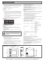
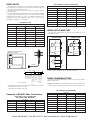
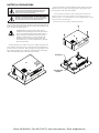
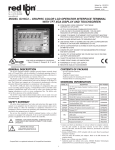
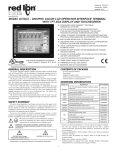
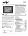
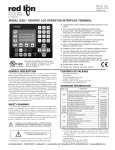
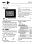
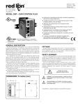
Bulletin No. G306A-G Drawing No. LP0666 Released 02/13 MODEL G306A - GRAPHIC COLOR LCD OPERATOR INTERFACE TERMINAL WITH TFT QVGA DISPLAY AND TOUCHSCREEN C UL R US LISTED FOR USE IN HAZARDOUS LOCATIONS: Class I, Division 2, Groups A, B, C, and D 43NH PROCESS CONTROL EQUIPMENT GENERAL DESCRIPTION CONFIGURED USING CRIMSON® SOFTWARE (BUILD 424 OR NEWER) UP TO 5 RS-232/422/485 COMMUNICATIONS PORTS (2 RS-232 AND 1 RS-422/485 ON BOARD, 1 RS-232 AND 1 RS422/485 ON OPTIONAL COMMUNICATIONS CARD) 10 BASE T/100 BASE-TX ETHERNET PORT TO NETWORK UNITS AND HOST WEB PAGES USB PORT TO DOWNLOAD THE UNIT’S CONFIGURATION FROM A PC OR FOR DATA TRANSFERS TO A PC UNIT’S CONFIGURATION IS STORED IN NON-VOLATILE MEMORY (8 MBYTE FLASH) COMPACTFLASH® SOCKET TO INCREASE MEMORY CAPACITY 5.7-INCH TFT ACTIVE MATRIX 256 COLOR QVGA 320 X 240 PIXEL LCD W/LED BACKLIGHT 5-BUTTON KEYPAD FOR ON-SCREEN MENUS THREE FRONT PANEL LED INDICATORS POWER UNIT FROM 24 VDC ±20% SUPPLY RESISTIVE ANALOG TOUCHSCREEN CONTENTS OF PACKAGE The G306A Operator Interface Terminal combines unique capabilities normally expected from high-end units with a very affordable price. It is built around a high performance core with integrated functionality. This core allows the G306A to perform many of the normal features of the Paradigm range of Operator Interfaces while improving and adding new features. The G306A is able to communicate with many different types of hardware using high-speed RS232/422/485 communications ports and Ethernet 10 Base T/100 Base-TX communications. In addition, the G306A features USB for fast downloads of configuration files and access to trending and data logging. A CompactFlash socket is provided so that Flash cards can be used to collect your trending and data logging information as well as to store larger configuration files. In addition to accessing and controlling of external resources, the G306A allows a user to easily view and enter information. Users can enter data through the touchscreen and/or front panel 5-button keypad. - G306A Operator Interface. - Panel gasket. - Template for panel cutout. - Hardware packet for mounting unit into panel. - Terminal block for connecting power. ORDERING INFORMATION MODEL NO. The protective conductor terminal is bonded to conductive parts of the equipment for safety purposes and must be connected to an external protective earthing system. PART NUMBER G306A G3CF CompactFlash Card 5 G3CFxxxx G3RS RS232/485 Optional Communication Card G3RS0000 G3CN CANopen Optional Communication Card G3CN0000 G3DN DeviceNet option card for G3 operator interfaces with isolated high speed communications ports G3DN0000 SAFETY SUMMARY All safety related regulations, local codes and instructions that appear in the manual or on equipment must be observed to ensure personal safety and to prevent damage to either the instrument or equipment connected to it. If equipment is used in a manner not specified by the manufacturer, the protection provided by the equipment may be impaired. Do not use the controller to directly command motors, valves, or other actuators not equipped with safeguards. To do so can be potentially harmful to persons or equipment in the event of a fault to the controller. DESCRIPTION Operator Interface for indoor applications, textured finish with embossed keys G3PBDP Profibus DP Optional Communication Card SFCRM2 Crimson 2.0 CBL 2 RS-232 Programming Cable CBLPROG0 USB Cable CBLUSB00 1 DIN Rail Mountable Adapter Products Replacement Battery G3FILM CBLxxxxx 3 4 Protective Films 1 WARNING - EXPLOSION HAZARD - SUBSTITUTION OF COMPONENTS MAY IMPAIR SUITABILITY FOR CLASS I, DIVISION 2 CAUTION: Risk Of Danger. Read complete instructions prior to installation and operation of the unit. CAUTION: Risk of electric shock. G3PBDP00 SFCRM200 Communications Cables DR G306A000 DRxxxxxx BNL20000 G3FILM06 Contact your Red Lion distributor or visit our website for complete selection. 2 Use this part number to purchase the Crimson® software on CD with a printed manual, USB cable, and RS-232 cable. Otherwise, download for free from Redlion website. 3 Red Lion offers RJ modular jack adapters. Refer to the DR literature for complete details. 4 Battery type is lithium coin type CR2025. 5 Industrial grade two million write cycles. CompactFlash is a registered trademark of CompactFlash Association. Phone: 800.894.0412 - Fax: 888.723.4773 - Web: www.clrwtr.com - Email: [email protected] Specifications 1. POWER REQUIREMENTS: Must use a Class 2 circuit according to National Electrical Code (NEC), NFPA-70 or Canadian Electrical Code (CEC), Part I, C22.1 or a Limited Power Supply (LPS) according to IEC 60950-1 or Limited-energy circuit according to IEC 61010-1. Power connection via removable three position terminal block. Supply Voltage: +24 VDC ±20% Typical Power1: 8W Maximum Power2: 10 W Notes: 1. Typical power with +24 VDC, RS232/485 communications, Ethernet communications, CompactFlash card installed, and display at full brightness. 2. Maximum power indicates the most power that can be drawn from the G306A. Refer to “Power Supply Requirements” under “Installing and Powering the G306A.” 3. The G306A’s circuit common is not connected to the enclosure of the unit. See “Connecting to Earth Ground” in the section “Installing and Powering the G306A.” 4. Read “Power Supply Requirements” in the section “Installing and Powering the G306A” for additional power supply information. 2. BATTERY: Lithium coin cell. Typical lifetime of 10 years. 3. LCD DISPLAY: SIZE 5.7-inch TYPE COLORS PIXELS BRIGHTNESS BACKLIGHT* TFT 256 320 X 240 380 cd/m2 50,000 HR TYP. *Lifetime at room temperature. Refer to “Display” in “Software/Unit Operation” 4. 5-KEY KEYPAD: for on-screen menus. 5. TOUCHSCREEN: Resistive analog 6. MEMORY: On Board User Memory: 8 Mbyte of non-volatile Flash memory. Memory Card: CompactFlash Type II slot for Type I and Type II CompactFlash cards. 7. COMMUNICATIONS: USB Port: Adheres to USB specification 1.1. Device only using Type B connection. WARNING - DO NOT CONNECT OR DISCONNECT CABLES WHILE POWER IS APPLIED UNLESS AREA IS KNOWN TO BE NON-HAZARDOUS. USB PORT IS FOR SYSTEM SET-UP AND DIAGNOSTICS AND IS NOT INTENDED FOR PERMANENT CONNECTION. Serial Ports: Format and Baud Rates for each port are individually software programmable up to 115,200 baud. PGM Port: RS232 port via RJ12. COMMS Ports: RS422/485 port via RJ45, and RS232 port via RJ12. DH485 TXEN: Transmit enable; open collector, VOH = 15 VDC, VOL = 0.5 V @ 25 mA max. Note: For additional information on the communications or signal common and connections to earth ground please see the “Connecting to Earth Ground” in the section “Installing and Powering the G306A.” Ethernet Port: 10 BASE-T / 100 BASE-TX RJ45 jack is wired as a NIC (Network Interface Card). Isolation from Ethernet network to G3 operator interface: 1500 Vrms 8. ENVIRONMENTAL CONDITIONS: Operating Temperature Range: 0 to 50°C Storage Temperature Range: -20 to 70°C Operating and Storage Humidity: 80% maximum relative humidity (noncondensing) from 0 to 50°C. Vibration according to IEC 68-2-6: Operational 5 to 8 Hz, 0.8" (p-p), 8 to 500 Hz, in X, Y, Z direction, duration: 1 hour, 3 g. Shock according to IEC 68-2-27: Operational 40 g, 9 msec in 3 directions. Altitude: Up to 2000 meters. 9. CERTIFICATIONS AND COMPLIANCES: SAFETY UL Listed, File #E245515, UL61010-1, ANSI/ISA 12.12.01-2007, CAN/CSA 22.2 No. 61010.1, CSA 22.2 No. 213-M1987 and File #E179259, UL61010‑1, CAN/CSA 22.2 No.61010-1 LISTED by Und. Lab. Inc. to U.S. and Canadian safety standards Type 4X Indoor Enclosure rating (Face only), UL50 IECEE CB Scheme Test Report #E179259-A1-CB-3 Issued by Underwriters Laboratories Inc. IEC 61010-1, EN 61010-1: Safety requirements for electrical equipment for measurement, control, and laboratory use, Part 1. IP66 Enclosure rating (Face only), IEC 529 ELECTROMAGNETIC COMPATIBILITY Emissions and Immunity to EN 61326: 2006: Electrical Equipment for Measurement, Control and Laboratory use. Immunity to Industrial Locations: Electrostatic discharge EN61000-4-2 Criterion A 4kV contact discharge 8kV air discharge Electromagnetic RF fields EN61000-4-3 Criterion A 10V/m (80 MHz to 1 GHz) 3 V/m (1.4 GHz to 2 GHz) 1 V/m (2 GHz to 2.7 GHz) Fast transients (burst) EN61000-4-4 Criterion A 2kV power 1kV I/O signal Surge EN61000-4-5 Criterion A 1kV L to L 2kV L to G power 1 kV signal RF conducted interference EN61000-4-6 Criterion A 3Vrms Power frequency magnetic EN61000-4-8 Criterion A 30A/m fields Emissions: Emissions EN55011 Class A Note: 1. Criterion A: Normal operation within specified limits. 10. CONNECTIONS: Compression cage-clamp terminal block. Wire Gage: 12-30 AWG copper wire Torque: 5-7 inch-pounds (56-79 N-cm) 11. CONSTRUCTION: Steel rear metal enclosure with NEMA 4X/IP66 aluminum front plate for indoor use only when correctly fitted with the gasket provided. Installation Category II, Pollution Degree 2. 12. MOUNTING REQUIREMENTS: Maximum panel thickness is 0.25" (6.3 mm). For NEMA 4X/IP66 sealing, a steel panel with a minimum thickness of 0.125" (3.17 mm) is recommended. Maximum Mounting Stud Torque: 17 inch-pounds (1.92 N-m) 13. WEIGHT: 3.0 lbs (1.36 Kg) DIMENSIONS In inches (mm) 2.30 (58.4) 8.83 (224.3) 7.08 (179.8) 7.42 (188.5) 5.67 (144) Phone: 800.894.0412 - Fax: 888.723.4773 - Web: www.clrwtr.com - Email: [email protected] Installing and Powering MOUNTING INSTRUCTIONS This operator interface is designed for through-panel mounting. A panel cutout diagram and a template are provided. Care should be taken to remove any loose material from the mounting cut-out to prevent that material from falling into the operator interface during installation. A gasket is provided to enable sealing to NEMA 4X/IP66 specification. Install the ten kep nuts provided and tighten evenly for uniform gasket compression. Note: Tightening the kep nuts beyond a maximum of 17 inch-pounds (1.92 N-m) may cause damage to the front panel. 8.25 (209.6) 10X Ø.188 (Ø4.8) 7.63 (193.8) 2.75 (69.9) 5.88 (149.4) 6.50 (165.1) All tolerances ±0.010" (±0.25 mm). ALL NONINCENDIVE CIRCUITS MUST BE WIRED USING DIVISION 2 WIRING METHODS AS SPECIFIED IN ARTICLE 501-4 (b), 502-4 (b), AND 503-3 (b) OF THE NATIONAL ELECTRICAL CODE, NFPA 70 FOR INSTALLATION WITHIN THE UNITED STATES, OR AS SPECIFIED IN SECTION 19-152 OF CANADIAN ELECTRICAL CODE FOR INSTALLATION IN CANADA. CONNECTING TO EARTH GROUND The protective conductor terminal is bonded to conductive parts of the equipment for safety purposes and must be connected to an external protective earthing system. Each G306A has a chassis ground terminal on the back of the unit. Your unit should be connected to earth ground (protective earth). the G306A The chassis ground is not connected to signal common of the unit. Maintaining isolation between earth ground and signal common is not required to operate your unit. But, other equipment connected to this unit may require isolation between signal common and earth ground. To maintain isolation between signal common and earth ground care must be taken when connections are made to the unit. For example, a power supply with isolation between its signal common and earth ground must be used. Also, plugging in a USB cable may connect signal common and earth ground.1 1 USB’s shield may be connected to earth ground at the host. USB’s shield in turn may also be connected to signal common. POWER SUPPLY REQUIREMENTS The G306A requires a 24 VDC power supply. Your unit may draw considerably less than the maximum rated power depending upon the options being used. As additional features are used your unit will draw increasing amounts of power. Items that could cause increases in current are additional communications, optional communications card, CompactFlash card, and other features programmed through Crimson. In any case, it is very important that the power supply is mounted correctly if the unit is to operate reliably. Please take care to observe the following points: – The power supply must be mounted close to the unit, with usually not more than 6 feet (1.8 m) of cable between the supply and the operator interface. Ideally, the shortest length possible should be used. – The wire used to connect the operator interface’s power supply should be at least 22-gage wire. If a longer cable run is used, a heavier gage wire should be used. The routing of the cable should be kept away from large contactors, inverters, and other devices which may generate significant electrical noise. – A power supply with an NEC Class 2 or Limited Power Source (LPS) and SELV rating is to be used. This type of power supply provides isolation to accessible circuits from hazardous voltage levels generated by a mains power supply due to single faults. SELV is an acronym for “safety extra-low voltage.” Safety extra-low voltage circuits shall exhibit voltages safe to touch both under normal operating conditions and after a single fault, such as a breakdown of a layer of basic insulation or after the failure of a single component has occurred. Installing An Option Card WARNING - EXPLOSION HAZARD - DO NOT DISCONNECT EQUIPMENT UNLESS POWER HAS BEEN DISCONNECTED AND THE AREA IS KNOWN TO BE NON-HAZARDOUS. Each option card comes with a cable for communications and three screws for ataching the option card to the G306’s rear cover. To install the option card, remove all power and I/O communications cables from the unit. Use the three screws provided to mount the option card to the rear cover of the G306 as shown in Figure 1. Figure 1 Connect the cable from the option card to CN11 on the main board of the G306 as shown in Figure 2. Be sure both ends of the cable are firmly seated into their appropriate connector housing. Carefully replace the rear cover by reversing the instructions for removing the rear cover. Figure 2 Phone: 800.894.0412 - Fax: 888.723.4773 - Web: www.clrwtr.com - Email: [email protected] Communicating With the G306A CONFIGURING A G306A CABLES AND DRIVERS The G306A is configured using Crimson® software. Crimson is available as a free download from Red Lion’s website, or it can be purchased on CD. Updates to Crimson for new features and drivers are posted on the website as they become available. By configuring the G306A using the latest version of Crimson, you are assured that your unit has the most up to date feature set. Crimson® software can configure the G306A through the RS232 PGM port, USB port, or CompactFlash. The USB port is connected using a standard USB cable with a Type B connector. The driver needed to use the USB port will be installed with Crimson. The RS232 PGM port uses a programming cable made by Red Lion to connect to the DB9 COM port of your computer. If you choose to make your own cable, use the “G306A Port Pin Out Diagram” for wiring information. The CompactFlash can be used to program a G3 by placing a configuration file and firmware on the CompactFlash card. The card is then inserted into the target G3 and powered. Refer to the Crimson literature for more information on the proper names and locations of the files. Red Lion has a wide range of cables and drivers for use with many different communication types. A list of these drivers and cables along with pin outs is available from Red Lion’s website. New cables and drivers are added on a regular basis. If making your own cable, refer to the “G306A Port Pin Outs” for wiring information. USB, DATA TRANSFERS FROM THE COMPACTFLASH CARD ETHERNET COMMUNICATIONS Ethernet communications can be established at either 10 BASE-T or 100 BASE-TX. The G306A unit’s RJ45 jack is wired as a NIC (Network Interface Card). For example, when wiring to a hub or switch use a straight-through cable, but when connecting to another NIC use a crossover cable. The Ethernet connector contains two LEDs. A yellow LED in the upper right, and a bi-color green/amber LED in the upper left. The LEDs represent the following statuses: LED COLOR WARNING - DO NOT CONNECT OR DISCONNECT CABLES WHILE POWER IS APPLIED UNLESS AREA IS KNOWN TO BE NON-HAZARDOUS. USB PORT IS FOR SYSTEM SET-UP AND DIAGNOSTICS AND IS NOT INTENDED FOR PERMANENT CONNECTION. DESCRIPTION YELLOW solid Link established. YELLOW flashing Data being transferred. GREEN 10 BASE-T Communications AMBER 100 BASE-TX Communications On the rear of each unit is a unique 12-digit MAC address and a block for marking the unit with an IP address. Refer to the Crimson manual and Red Lion’s website for additional information on Ethernet communications. In order to transfer data from the CompactFlash card via the USB port, a driver must be installed on your computer. This driver is installed with Crimson and is located in the folder C:\Program Files\Red Lion Controls\Crimson 2.0\Device\ after Crimson is installed. This may have already been accomplished if your G306A was configured using the USB port. Once the driver is installed, connect the G306A to your PC with a USB cable, and follow “Mounting the CompactFlash” instructions in the Crimson 2 user manual. USB TYPE B CTS (PIN 1) Rx COMM COMM Tx RTS (PIN 6) N/C 3 TxB (PIN 1) TxA RxA RxB TxEN COMM TxB TxA (PIN 8) 24V + - 20% 2 POWER CONNECTOR ETHERNET (NIC) CTS (PIN 1) Rx COMM COMM Tx RTS (PIN 6) COMMON 1 G306A PORT PIN OUTS RS232 RS485 RS232 COMMS PORT COMMS PORT PGM PORT Phone: 800.894.0412 - Fax: 888.723.4773 - Web: www.clrwtr.com - Email: [email protected] RS232 PORTS G3 to Modular Controller (CBLRLC05) The G306A has two RS232 ports. There is the PGM port and the COMMS port. Although only one of these ports can be used for programming, both ports can be used for communications with a PLC. The RS232 ports can be used for either master or slave protocols with any G306A configuration. Examples of RS232 communications could involve another Red Lion product or a PC. By using a cable with RJ12 ends on it, and a twist in the cable, RS232 communications with another G3 product or the Modular Controller can be established. Red Lion part numbers for cables with a twist in them are CBLPROG0 1, CBLRLC01 2, or CBLRC02 3. Name Modular Controller Name 1,4 TxB 1,4 TxB 4,1 RxB 4,1 RxB 2,3 TxA 2,3 TxA 3,2 RxA 3,2 RxA 5 TxEN 5 TxEN 6 COM 6 COM G3 RS232 to a PC 7 TxB 7 TxB Connections 8 TxA 8 TxA G3: RJ12 Name PC: DB9 Name 4 COMM 1 DCD 5 Tx 2 Rx 2 Rx 3 Tx N/C 4 DTR COM 5 GND N/C 6 DSR 1 CTS 7 RTS 6 RTS 8 CTS 3 Connections G3 N/C 9 RS422/485 COMMS PORT The G306A has one RS422/485 port. This port can be configured to act as either RS422 or RS485. RS422/485 4-WIRE CONNECTIONS RS485 2-WIRE CONNECTIONS 5V 5V 130K 7 1 RI 130K TxB 7 1 TX TxB TX/RX 8 130K 2 8 TxA 130K 2 TxA ICM5 5 CONNECTING A G306A OPERATOR INTERFACE TO AN ICM5 TxEN (OC) 5 TxEN (OC) 6 GND 5V 130K 4 RxB 3 RxA 6 GND RX 130K CBLPROG0 Note: All Red Lion devices connect A to A and B to B, except for Paradigm devices. Refer to Redlion website for additional information. OFF 422/ ON 485 OFF 422/ ON 485 NC OFF DCE/ ON DTE OFF DCE/ ON DTE OFF DTE/ ON DCE OFF DTE/ ON DCE 1 2 3 4 5 6 7 * * * * * 9600 BAUD 1 19200 BAUD 2 38400 BAUD 3 57600 BAUD 4 115200 BAUD 5 PULL DOWN 6 PULL UP 7 OFF 4 WIRE/ ON 2 WIRE 8 OFF 4 WIRE/ ON 2 WIRE 9 120 Ω TERMINATION 10 * * * * * ON ON ICM5 DIP Switch Settings DH485 COMMUNICATIONS The G306A’s RS422/485 COMMS port can also be used for Allen Bradley DH485 communications. * Application Dependent 1 CBLPROG0 can also be used to communicate with either a PC or an ICM5. 2 3 WARNING: DO NOT use a standard DH485 cable to connect this port to Allen Bradley equipment. A cable and wiring diagram are available from Red Lion. DB9 adapter not included, 1 foot long. DB9 adapter not included, 10 feet long. G3 to AB SLC 500 (CBLAB003) Examples of RS485 2-Wire Connections G3 to Red Lion RJ11 (CBLRLC00) DLC, IAMS, ITMS, PAXCDC4C Connections G3: RJ45 Name RLC: RJ11 Name 5 TxEN 2 TxEN 6 COM 3 COM 1 TxB 5 B- 2 TxA 4 A+ Connections RJ45: RLC Name RJ45: A-B 1 TxB 1 Name A 2 TxA 2 B 3, 8 RxA - 24V COMM 4, 7 RxB - 5 TxEN 5 TxEN 6 COMM 4 SHIELD 4, 7 TxB - COMM 3, 8 TxA - 24V Phone: 800.894.0412 - Fax: 888.723.4773 - Web: www.clrwtr.com - Email: [email protected] Software/Unit Operation CRIMSON® SOFTWARE TOUCHSCREEN Crimson® software is available as a free download from Red Lion’s website or it can be purchased on a CD, see “Ordering Information” for part number. The latest version of the software is always available from the website, and updating your copy is free. This operator interface utilizes a resistive analog touchscreen for user input. The unit will only produce an audible tone (beep) when a touch on an active touchscreen cell is sensed. The touchscreen is fully functional as soon as the operator interface is initialized, and can be operated with gloved hands. DISPLAY KEYPAD This operator interface uses a liquid crystal display (LCD) for displaying text and graphics. The display utilizes aa LED backlight for lighting the display. The backlight can be dimmed for low light conditions. The LED backlight has a limited lifetime. Backlight lifetime is based upon the amount of time the display is turned on at full intensity. Turning the backlight off when the display is not in use can extend the lifetime of your backlight. This can be accomplished through the Crimson® software when configuring your unit. The G306A keypad consists of five keys that can be used for on-screen menus. TROUBLESHOOTING YOUR G306A If for any reason you have trouble operating, connecting, or simply have questions concerning your new G306A, contact Red Lion’s technical support. For contact information, refer to the back page of this bulletin for phone and fax numbers. FRONT PANEL LEDS There are three front panel LEDs. Shown below is the default status of the LEDs. LED INDICATION RED (TOP, LABELED “PWR”) FLASHING STEADY Unit is in the boot loader, no valid configuration is loaded.1 Unit is powered and running an application. YELLOW (MIDDLE) OFF No CompactFlash card is present. STEADY Valid CompactFlash card present. FLASHING RAPIDLY CompactFlash card being checked. Unit is writing to the CompactFlash, either because it is FLICKERING storing data, or because the PC connected via the USB port has locked the drive.2 FLASHING SLOWLY Incorrectly formatted CompactFlash card present. GREEN (BOTTOM) FLASHING STEADY A tag is in an alarm state. Valid configuration is loaded and there are no alarms present. 1 The operator interface is shipped without a configuration. After downloading 2 a configuration, if the light remains in the flashing state continuously, try cycling power. If the LED still continues to flash, try downloading a configuration again. Do not turn off power to the unit while this light is flickering. The unit writes data in two minute intervals. Later Microsoft operating systems will not lock the drive unless they need to write data; Windows 98 may lock the drive any time it is mounted, thereby interfering with logging. Refer to “Mounting the CompactFlash” in the Crimson 2 User Manual. Phone: 800.894.0412 - Fax: 888.723.4773 - Web: www.clrwtr.com - Email: [email protected] BATTERY & TIME KEEPING WARNING - EXPLOSION HAZARD - THE AREA MUST BE KNOWN TO BE NON-HAZARDOUS BEFORE SERVICING/ REPLACING THE UNIT AND BEFORE INSTALLING OR REMOVING I/O WIRING AND BATTERY. WARNING - EXPLOSION HAZARD - DO NOT DISCONNECT EQUIPMENT UNLESS POWER HAS BEEN DISCONNECTED AND THE AREA IS KNOWN TO BE NON-HAZARDOUS. A battery is used to keep time when the unit is without power. Typical accuracy of the G306A time keeping is less than one minute per month drift. The battery of a G306A unit does not affect the unit’s memory, all configurations and data is stored in non-volatile memory. Remove the old battery* from the holder and replace with the new battery. Replace the rear cover, cables, and re-apply power. Using Crimson or the unit’s keypad, enter the correct time and date. * Please note that the old battery must be disposed of in a manner that complies with your local waste regulations. Also, the battery must not be disposed of in fire, or in a manner whereby it may be damaged and its contents come into contact with human skin. The battery used by the G306A is a lithium type CR2025. CAUTION: The circuit board contains static sensitive components. Before handling the operator interface without the rear cover attached, discharge static charges from your body by touching a grounded bare metal object. Ideally, handle the operator interface at a static controlled clean workstation. Also, do not touch the surface areas of the circuit board. Dirt, oil, or other contaminants may adversely affect circuit operation. To change the battery of a G306A, remove power, cabling, and then the rear cover of the unit. To remove the cover, remove the four screws designated by the arrows on the rear of the unit. Then, by lifting the top side, hinge the cover, thus providing clearance for the connectors on the bottom side of the PCB as shown in the illustration below. Install in the reverse manner. BATTERY LED DRIVER BOARD Phone: 800.894.0412 - Fax: 888.723.4773 - Web: www.clrwtr.com - Email: [email protected] Optional Features and Accessories OPTIONAL COMMUNICATION CARD COMPACTFLASH SOCKET Red Lion offers optional communication cards for fieldbus communications. These communication cards will allow your G306A to communicate with many of the popular fieldbus protocols. Red Lion is also offering a communications card for additional RS232 and RS422/485 communications. Visit Red Lion’s website for information and availability of these cards. CompactFlash socket is a Type II socket that can accept either Type I or II cards. Use cards with a minimum of 4 Mbytes and formatted to a maximum of 2 Gbytes (See Note box below) with the G306A’s CompactFlash socket. Cards are available at most computer and office supply retailers. CompactFlash can be used for configuration transfers, larger configurations, data logging, and trending. CUSTOM LOGO Each G3 operator interface has an embossed area containing the Red Lion logo. Red Lion can provide custom logos to apply to this area. Contact your distributor for additional information and pricing. C om (T pac op tF S las id h e) .51 (13) 1.65 (42) FRONT OVERLAY CompactFlashInsert Face Up Note: Do not remove or insert the CompactFlash card while power is applied. Refer to “Front Panel LEDs.” Information stored on a CompactFlash card by a G306A can be read by a card reader attached to a PC. This information is stored in IBM (Windows®) PC compatible FAT16 file format. NOTE For reliable operation of this and other Red Lion products, one of the following brands of CompactFlash card must be used... SimpleTechSMART® Modular SanDisk® Silicon Systems Not all of the above manufacturers offer CompactFlash cards recognized to UL standards, which may be required for your application. Although RLC products limit use of CompactFlash card memory to 2 GB, cards with a larger capacity can be used. They MUST be formatted to 2 GB and use the FAT 16 file system. It is recommended to format the CF card using the format utility from within Crimson. LIMITED WARRANTY The Company warrants the products it manufactures against defects in materials and workmanship for a period limited to two years from the date of shipment, provided the products have been stored, handled, installed, and used under proper conditions. The Company’s liability under this limited warranty shall extend only to the repair or replacement of a defective product, at The Company’s option. The Company disclaims all liability for any affirmation, promise or representation with respect to the products. The customer agrees to hold Red Lion Controls harmless from, defend, and indemnify RLC against damages, claims, and expenses arising out of subsequent sales of RLC products or products containing components manufactured by RLC and based upon personal injuries, deaths, property damage, lost profits, and other matters which Buyer, its employees, or sub-contractors are or may be to any extent liable, including without limitation penalties imposed by the Consumer Product Safety Act (P.L. 92-573) and liability imposed upon any person pursuant to the Magnuson-Moss Warranty Act (P.L. 93-637), as now in effect or as amended hereafter. No warranties expressed or implied are created with respect to The Company’s products except those expressly contained herein. The Customer acknowledges the disclaimers and limitations contained herein and relies on no other warranties or affirmations. Phone: 800.894.0412 - Fax: 888.723.4773 - Web: www.clrwtr.com - Email: [email protected]