1
Dialogic® CX 2000C CompactPCI Station
Interface Board Installation and Developer’s
Manual
October 2010
64-0487-03 Rev A
www.dialogic.com
Copyright and legal notices
Copyright © 2002-2010 Dialogic Corporation. All Rights Reserved. You may not reproduce this document in whole or in
part without permission in writing from Dialogic Corporation at the address provided below.
All contents of this document are furnished for informational use only and are subject to change without notice and do not
represent a commitment on the part of Dialogic Corporation or its subsidiaries (“Dialogic”). Reasonable effort is made to
ensure the accuracy of the information contained in the document. However, Dialogic does not warrant the accuracy of this
information and cannot accept responsibility for errors, inaccuracies or omissions that may be contained in this document.
INFORMATION IN THIS DOCUMENT IS PROVIDED IN CONNECTION WITH DIALOGIC® PRODUCTS. NO LICENSE, EXPRESS
OR IMPLIED, BY ESTOPPEL OR OTHERWISE, TO ANY INTELLECTUAL PROPERTY RIGHTS IS GRANTED BY THIS DOCUMENT.
EXCEPT AS PROVIDED IN A SIGNED AGREEMENT BETWEEN YOU AND DIALOGIC, DIALOGIC ASSUMES NO LIABILITY
WHATSOEVER, AND DIALOGIC DISCLAIMS ANY EXPRESS OR IMPLIED WARRANTY, RELATING TO SALE AND/OR USE OF
DIALOGIC PRODUCTS INCLUDING LIABILITY OR WARRANTIES RELATING TO FITNESS FOR A PARTICULAR PURPOSE,
MERCHANTABILITY, OR INFRINGEMENT OF ANY INTELLECTUAL PROPERTY RIGHT OF A THIRD PARTY.
Dialogic products are not intended for use in medical, life saving, life sustaining, critical control or safety systems, or in
nuclear facility applications.
Due to differing national regulations and approval requirements, certain Dialogic products may be suitable for use only in
specific countries, and thus may not function properly in other countries. You are responsible for ensuring that your use of
such products occurs only in the countries where such use is suitable. For information on specific products, contact Dialogic
Corporation at the address indicated below or on the web at www.dialogic.com.
It is possible that the use or implementation of any one of the concepts, applications, or ideas described in this document,
in marketing collateral produced by or on web pages maintained by Dialogic may infringe one or more patents or other
intellectual property rights owned by third parties. Dialogic does not provide any intellectual property licenses with the sale
of Dialogic products other than a license to use such product in accordance with intellectual property owned or validly
licensed by Dialogic and no such licenses are provided except pursuant to a signed agreement with Dialogic. More detailed
information about such intellectual property is available from Dialogic’s legal department at 9800 Cavendish Blvd., 5th
Floor, Montreal, Quebec, Canada H4M 2V9. Dialogic encourages all users of its products to procure all necessary
intellectual property licenses required to implement any concepts or applications and does not condone or encourage any
intellectual property infringement and disclaims any responsibility related thereto. These intellectual property licenses may
differ from country to country and it is the responsibility of those who develop the concepts or applications to be aware of
and comply with different national license requirements.
Any use case(s) shown and/or described herein represent one or more examples of the various ways, scenarios or
environments in which Dialogic® products can be used. Such use case(s) are non-limiting and do not represent
recommendations of Dialogic as to whether or how to use Dialogic products.
Dialogic, Dialogic Pro, Brooktrout, Diva, Cantata, SnowShore, Eicon, Eicon Networks, NMS Communications, NMS
(stylized), Eiconcard, SIPcontrol, Diva ISDN, TruFax, Exnet, EXS, SwitchKit, N20, Making Innovation Thrive, Connecting to
Growth, Video is the New Voice, Fusion, Vision, PacketMedia, NaturalAccess, NaturalCallControl, NaturalConference,
NaturalFax and Shiva, among others as well as related logos, are either registered trademarks or trademarks of Dialogic
Corporation or its subsidiaries. Dialogic's trademarks may be used publicly only with permission from Dialogic. Such
permission may only be granted by Dialogic’s legal department at 9800 Cavendish Blvd., 5th Floor, Montreal, Quebec,
Canada H4M 2V9. Any authorized use of Dialogic's trademarks will be subject to full respect of the trademark guidelines
published by Dialogic from time to time and any use of Dialogic’s trademarks requires proper acknowledgement.
Windows is a registered trademark of Microsoft Corporation in the United States and/or other countries. The names of
actual companies and product mentioned herein are the trademarks of their respective owners.
This document discusses one or more open source products, systems and/or releases. Dialogic is not responsible for your
decision to use open source in connection with Dialogic products (including without limitation those referred to herein), nor
is Dialogic responsible for any present or future effects such usage might have, including without limitation effects on your
products, your business, or your intellectual property rights.
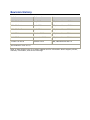
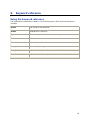
Revision history
Revision
Release date
Notes
9000-62161-10
May 2002
NBS, Natural Access 2002-1
9000-62161-11
April 2003
SRG, Natural Access 2003-1
9000-62161-12
April 2004
SRR, Natural Access 2004-1
64-0487-01
October 2009
LBG, NaturalAccess R9.0
64-0487-02
December 2009
LBG, NaturalAccess R9.0.1
64-0487-03 Rev A
October 2010
LBG, NaturalAccess R9.0.4
Last modified: 2010-10-15
Refer to www.dialogic.com for product updates and for information about support policies,
warranty information, and service offerings.
Table Of Contents
1.
Introduction .................................................................................................. 7
2.
Overview of the CX 2000C board.................................................................. 10
CX 2000C board features........................................................................................ 10
Power supply ..................................................................................................... 13
Developer's cable kit ........................................................................................... 13
Software components ............................................................................................ 13
Natural Access ................................................................................................... 13
NMS OAM .......................................................................................................... 14
CX board plug-in ................................................................................................ 14
Configuration files............................................................................................... 15
CDI service ........................................................................................................ 15
CX driver software .............................................................................................. 15
Installation summary ............................................................................................. 16
3.
Installing a CX 2000C board ........................................................................ 17
System requirements ............................................................................................. 17
Selecting a CompactPCI chassis............................................................................ 18
Board components................................................................................................. 20
Configuring the internal ringer unit .......................................................................... 22
Grounding the chassis ............................................................................................ 23
Keying the chassis ................................................................................................. 23
Installing the board ............................................................................................... 27
Connecting to station telephones ............................................................................. 29
Cabling considerations......................................................................................... 29
Cable connections ............................................................................................... 31
Developer's cable kit ........................................................................................... 34
4.
Connecting a power supply .......................................................................... 35
Using the NMS rack mount power supply chassis ....................................................... 35
Normal configuration........................................................................................... 36
Redundant power supply configuration .................................................................. 36
Rack mount considerations .................................................................................. 37
Connecting the NMS power supply ........................................................................ 38
Powering up the power supply .............................................................................. 40
Using an alternative power supply ........................................................................... 41
Power supply requirements .................................................................................. 41
Connecting an alternative power supply ................................................................ 43
5.
Configuring the board .................................................................................. 44
Referencing the CDI manager for Natural Access ....................................................... 44
Adding board configurations to the NMS OAM database .............................................. 44
Configuring and starting the system using oamsys .................................................... 45
Creating a system configuration file for oamsys......................................................... 45
Sample system configuration file .......................................................................... 47
Running oamsys .................................................................................................... 47
Changing configuration parameter settings ............................................................... 48
Configuring ring cadences ...................................................................................... 49
Default ring cadences.......................................................................................... 50
Using the Hot Swap features ................................................................................... 51
Configuring board clocking...................................................................................... 52
CX 2000C clocking capabilities ............................................................................. 52
iv
Table Of Contents
Clocking configurations........................................................................................ 55
Configuring CX 2000C board clocking using keywords ............................................. 56
Examples........................................................................................................... 58
CX 2000C clocking exceptions .............................................................................. 61
Notes on modem connections ................................................................................. 62
6.
Verifying the installation.............................................................................. 63
CX 2000C status indicator LEDs .............................................................................. 63
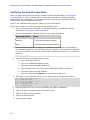
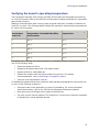
Verifying the board installation ................................................................................ 65
Verifying the board's operation................................................................................ 66
Verifying the board's operating temperature ............................................................. 67
7.
Implementing switching .............................................................................. 68
CX 2000C switch model .......................................................................................... 68
H.110 streams ................................................................................................... 68
Local streams..................................................................................................... 68
Switch model ..................................................................................................... 69
Lucent T8100A switch blocking ............................................................................. 69
Default connections for a standalone board............................................................... 70
Using the Switching service .................................................................................... 70
Opening the switch ............................................................................................. 70
Configuring local devices ..................................................................................... 70
Accessing the line gain ........................................................................................... 71
Getting the line gain ........................................................................................... 71
Setting the line gain ............................................................................................ 73
8.
Keyword summary ....................................................................................... 75
Using keywords ..................................................................................................... 75
Setting keyword values ....................................................................................... 75
Retrieving keyword values ................................................................................... 76
Editable keywords ................................................................................................. 77
Informational keywords.......................................................................................... 79
Retrieving board information ................................................................................ 79
Retrieving EEPROM information ............................................................................ 79
Plug-in keywords ................................................................................................... 80
9.
Keyword reference....................................................................................... 81
Using the keyword reference................................................................................... 81
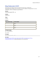
AutoStart ............................................................................................................. 82
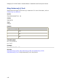
AutoStop .............................................................................................................. 83
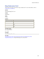
Boards[x] ............................................................................................................. 84
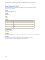
BootDiagnosticLevel............................................................................................... 85
Clocking.HBus.AutoFallBack .................................................................................... 86
Clocking.HBus.ClockMode ....................................................................................... 87
Clocking.HBus.ClockSource..................................................................................... 88
Clocking.HBus.ClockSourceNetwork ......................................................................... 90
Clocking.HBus.FallbackClockSource ......................................................................... 91
Clocking.HBus.NetRef2Source ................................................................................. 93
Clocking.HBus.NetRef2Speed .................................................................................. 94
Clocking.HBus.NetRefSource ................................................................................... 95
Clocking.HBus.NetRefSpeed .................................................................................... 96
Clocking.HBus.SClockSpeed .................................................................................... 97
Clocking.HBus.Segment ......................................................................................... 98
Clocking.Type ....................................................................................................... 99
DebugMask......................................................................................................... 100
v
Dialogic® CX 2000C Station Interface Board Installation and Developer's Manual
DefaultQslacFile .................................................................................................. 102
DetectedBoards[x] .............................................................................................. 103
DSPFile .............................................................................................................. 104
DSP.Image ......................................................................................................... 105
Encoding ............................................................................................................ 106
ExternalRingerEnable ........................................................................................... 107
HighBatteryEnable ............................................................................................... 108
Location.PCI.Bus ................................................................................................. 109
Location.PCI.Slot ................................................................................................. 110
LowBatteryEnable................................................................................................ 111
Name................................................................................................................. 112
Number.............................................................................................................. 113
Products[x]......................................................................................................... 114
Ring.Cadences[x].Toff1 ........................................................................................ 115
Ring.Cadences[x].Toff2 ........................................................................................ 116
Ring.Cadences[x].Toff3 ........................................................................................ 117
Ring.Cadences[x].Ton1 ........................................................................................ 118
Ring.Cadences[x].Ton2 ........................................................................................ 119
Ring.Cadences[x].Ton3 ........................................................................................ 120
Ring.Period ......................................................................................................... 121
RingVoltageEnable ............................................................................................... 122
SignalingLoopbackEnable ..................................................................................... 123
SwitchConnections............................................................................................... 124
SwitchDriver.Name .............................................................................................. 125
Version.Major ..................................................................................................... 126
Version.Minor...................................................................................................... 127
10. Demonstration program............................................................................. 128
Using CX demonstration programs......................................................................... 128
Interactive test program: cditest ........................................................................... 129
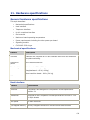
11. Hardware specifications............................................................................. 131
General hardware specifications ............................................................................ 131
Mechanical specifications ................................................................................... 131
Host interface .................................................................................................. 131
Telephone interface .......................................................................................... 132
H.110 compliant interface .................................................................................. 132
Environment .................................................................................................... 132
Maximum board operating temperature ............................................................... 132
Power requirements .......................................................................................... 133
Signaling module .............................................................................................. 133
CX 2000C-32-R ringer ....................................................................................... 134
Rack mount ringing power supply specifications ................................................... 134
12.
vi
Index ......................................................................................................... 137
1.
Introduction
The Dialogic® CX 2000C CompactPCI Station Interface Board Installation and Developer’s
Manual explains how to:
•
Select a proper chassis for safety and heat considerations
•
Install a CX 2000C board in a chassis
•
Configure external power supplies
•
Install the driver software
•
Verify that the board has been installed correctly and is operating correctly
•
Perform CT bus switching
This manual targets programmers and system integrators who develop media server
applications. This manual defines telephony terms where applicable, but assumes that the
reader is familiar with basic telephony and Internet data communication concepts,
switching, and the C programming language.
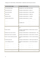
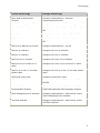
Terminology
Note: The product to which this document pertains is part of the NMS Communications
Platforms business that was sold by NMS Communications Corporation (“NMS”) to Dialogic
Corporation (“Dialogic”) on December 8, 2008. Accordingly, certain terminology relating to
the product has been changed. Below is a table indicating both terminology that was
formerly associated with the product, as well as the new terminology by which the product
is now known. This document is being published during a transition period; therefore, it may
be that some of the former terminology will appear within the document, in which case the
former terminology should be equated to the new terminology, and vice versa.
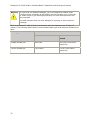
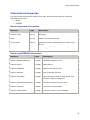
Former terminology
Dialogic terminology
CG 6060 Board
Dialogic® CG 6060 PCI Media Board
CG 6060C Board
Dialogic® CG 6060C CompactPCI Media Board
CG 6565 Board
Dialogic® CG 6565 PCI Media Board
CG 6565C Board
Dialogic® CG 6565C CompactPCI Media Board
CG 6565e Board
Dialogic® CG 6565E PCI Express Media Board
CX 2000 Board
Dialogic® CX 2000 PCI Station Interface Board
CX 2000C Board
Dialogic® CX 2000C CompactPCI Station Interface
Board
AG 2000 Board
Dialogic® AG 2000 PCI Media Board
AG 2000C Board
Dialogic® AG 2000C CompactPCI Media Board
7
Dialogic® CX 2000C Station Interface Board Installation and Developer's Manual
Former terminology
Dialogic terminology
AG 2000-BRI Board
Dialogic® AG 2000-BRI Media Board
NMS OAM Service
Dialogic® NaturalAccess™ OAM API
NMS OAM System
Dialogic® NaturalAccess™ OAM System
NMS SNMP
Dialogic® NaturalAccess™ SNMP API
Natural Access
Dialogic® NaturalAccess™ Software
Natural Access Service
Dialogic® NaturalAccess™ Service
Fusion
Dialogic® NaturalAccess™ Fusion™ VoIP API
ADI Service
Dialogic® NaturalAccess™ Alliance Device
Interface API
CDI Service
Dialogic® NaturalAccess™ CX Device Interface API
Digital Trunk Monitor Service
Dialogic® NaturalAccess™ Digital Trunk Monitoring
API
MSPP Service
Dialogic® NaturalAccess™ Media Stream Protocol
Processing API
Natural Call Control Service
Dialogic® NaturalAccess™ NaturalCallControl™ API
NMS GR303 and V5 Libraries
Dialogic® NaturalAccess™ GR303 and V5 Libraries
Point-to-Point Switching Service
Dialogic® NaturalAccess™ Point-to-Point Switching
API
Switching Service
Dialogic® NaturalAccess™ Switching Interface API
Voice Message Service
Dialogic® NaturalAccess™ Voice Control Element
API
NMS CAS for Natural Call Control
Dialogic® NaturalAccess™ CAS API
NMS ISDN
Dialogic® NaturalAccess™ ISDN API
NMS ISDN for Natural Call Control
Dialogic® NaturalAccess™ ISDN API
NMS ISDN Messaging API
Dialogic® NaturalAccess™ ISDN Messaging API
8
Terminology
Former terminology
Dialogic terminology
NMS ISDN Supplementary
Services
Dialogic® NaturalAccess™ ISDN API
Supplementary Services
NMS ISDN Management API
Dialogic® NaturalAccess™ ISDN Management API
NaturalConference Service
Dialogic® NaturalAccess™ NaturalConference™
API
NaturalFax
Dialogic® NaturalAccess™ NaturalFax™ API
SAI Service
Dialogic® NaturalAccess™ Universal Speech Access
API
NMS SIP for Natural Call Control
Dialogic® NaturalAccess™ SIP API
NMS RJ-45 interface
Dialogic® MD1 RJ-45 interface
NMS RJ-21 interface
Dialogic® MD1 RJ-21 interface
NMS Mini RJ-21 interface
Dialogic® MD1 Mini RJ-21 interface
NMS Mini RJ-21 to NMS RJ-21
cable
Dialogic® MD1 Mini RJ-21 to MD1 RJ-21 cable
NMS RJ-45 to two 75 ohm BNC
splitter cable
Dialogic® MD1 RJ-45 to two 75 ohm BNC splitter
cable
NMS signal entry panel
Dialogic® Signal Entry Panel
Video Access Utilities
Dialogic® NaturalAccess™ Video Access Toolkit
Utilities
Video Mail Application
Demonstration Program
Dialogic® NaturalAccess™ Video Access Toolkit
Video Mail Application Demonstration Program
Video Messaging Server Interface
Dialogic® NaturalAccess™ Video Access Toolkit
Video Messaging Server Interface
3G-324M Interface
Dialogic® NaturalAccess™ Video Access Toolkit
3G-324M Interface
9
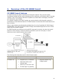
2.
Overview of the CX 2000C board
CX 2000C board features
CX 2000C boards are station interfaces for Enterprise markets. They provide analog
interfaces to analog devices such as telephones, fax machines, and modems within a private
network. They can be used to build such systems as private branch exchanges, automatic
call distributors, and IP-PBXs.
In a system containing CX 2000C boards, any communication with the public network is
performed by trunk interface boards. CX 2000C boards communicate with these boards over
the H.110 bus.
Refer to www.dialogic.com/declarations/default.htm for a list of available CX 2000C board
configurations, for a list of countries where Dialogic has obtained approval for the CX 2000
board, and for product updates.
CX 2000C boards have sufficient on-board DSP resources for simple, low-level call control
functions. More complex, resource-intensive operations (such as voice play or record
functions) must be performed by other boards.
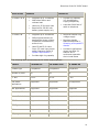
The following table describes each CX 2000C board model:
Board model
CX 2000C-32
Features
•
Supports up to 32 stations
•
Maximizes airflow and
reduces heat
•
Uses only J5 for telco lines
•
Provides high ring capacity
Limitations
•
Requires external ring
voltage supply
10
Overview of the CX 2000C board
Board model
Features
CX 2000C-32-R
CX 2000C-48
Limitations
•
Supports up to 32 stations
•
Maximizes airflow and
reduces heat
•
Uses only J5 for telco lines
•
Requires 24-32V DC talk
battery power supply only
•
Supports up to 48 stations
•
Offers highest density for
applications where number
of stations simultaneously
active is low
•
Uses J3 and J5 for telco
lines. (J3 must have proper
safety clearance. Refer to
System requirements.)
•
Provides high ring capacity
•
Limited ring capacity
(12 simultaneous
ringing telephones)
•
Less than 2000 feet of
cable to telephone
•
Requires external ring
voltage supply
•
Requires chassis
features described in
Selecting a CompactPCI
chassis
•
Limited to applications
where less than 24
stations are in
continuous operation
due to heat issues
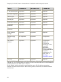
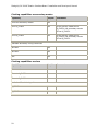
The following table summarizes the CX 2000C board features:
Feature
CX 2000C-32
CX 2000C-32-R
CX 2000C-48
Chassis type
CompactPCI
CompactPCI
CompactPCI
Number of ports
32
32
48
CT bus
H.110
H.110
H.110
Call center
applications
Supported
Supported
Not supported
PBX applications
Supported
Supported
Supported
Detect on/off hook
Supported
Supported
Supported
Detect flash-hook
Supported
Supported
Supported
DTMF detection
Supported
Supported
Supported
DTMF generation
Supported
Supported
Supported
Dial tone
Supported
Supported
Supported
Call progress tones
Supported
Supported
Supported
11
Dialogic® CX 2000C Station Interface Board Installation and Developer's Manual
Feature
CX 2000C-32
CX 2000C-32-R
CX 2000C-48
CT bus switching API
Supported
Supported
Supported
Heart beat diagnostic Supported
Supported
Supported
Transmit gain
Supported
Supported
Supported
Receive gain
Supported
Supported
Supported
Temperature sensors
Supported
Supported
Supported
On premise
extensions
Supported
Supported
Supported
Off premise
extensions
Supported
Not supported
Supported
Wiring between
buildings
Supported
Supported
Supported
Internal ringing
supply
Not supported
Supported
Not supported
Easy chassis
selection
Supported
Supported
Not supported.
Hot Swap
Supported
Because the
CX 2000C-48
exceeds the 32-line
CompactPCI
specification,
selecting a chassis
for these applications
has special
considerations. For
details, refer to
Selecting a
CompactPCI chassis.
Supported
Supported
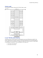
The CX 2000C fully supports the H.110 bus specification. Switching is implemented with the
T8100A chip. The T8100A offers full support for the H.110 bus within the H.110 architecture
providing access to all 4096 slots on the bus.
On the boards, switch connections are allowed for up to 128 full duplex connections
between local devices and the bus. Non-blocking switch connections are allowed between
local devices.
12
Overview of the CX 2000C board
Power supply
To provide power for talk battery and for ringing station phones (if necessary), an external
power supply is required. NMS Communications supplies a rack mount power supply chassis
that can contain up to four interchangeable supply modules. Alternatively, you can obtain a
power supply from another source. You can connect the power supply to each board.
Alternately, if you are using a CompactPCI chassis whose backplane has a telecom power
bus, you can use a single cable to connect one of the modules to the bus.
For more information on choosing and connecting power supplies, refer to Using the NMS
rack mount power supply chassis.
Developer's cable kit
To make connecting telephones to CX 2000C boards easier, a developer's cable kit is
available. It consists of the following components:
•
Two RJ-21, twenty-five pair, 10 feet cables
•
Two breakout boxes RJ-21 to 25 RJ-11
For more information about the developer's cable kit, refer to Connecting to station
telephones.
Software components
CX 2000C boards require the following software components:
•
The Natural Access development environment that provides services for call control,
voice store and forward, and other functions.
•
NMS OAM (Operations, Administration, and Maintenance) software and related
utilities
•
The CX 2000C software package that includes the:
•
CX board plug-in
•
Configuration files
•
CDI service DLLs and libraries that provide the call control functions on
CX 2000C boards
•
CX device drivers and downloadable firmware
Natural Access
Natural Access is a complete software development environment for voice applications. It
provides a standard set of functions grouped into logical services. Each service has a
standard programming interface. For more information about standard and optional Natural
Access services, refer to the Natural Access Developer's Reference Manual.
13
Dialogic® CX 2000C Station Interface Board Installation and Developer's Manual
NMS OAM
NMS OAM manages and maintains the telephony resources in a system. These resources
include hardware components (including CX boards) and low-level board management
software modules (such as clock management).
Using NMS OAM, you can:
•
Create, delete, and query the configuration of a component
•
Start (boot), stop (shut down), and test a component
•
Receive notifications from components
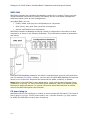
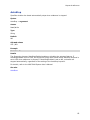
NMS OAM maintains a database containing records of configuration information for each
component, as shown in the following illustration. This information consists of parameters
and values.
Each NMS OAM database parameter and value is expressed as a keyword name and value
pair (for example, Encoding = MuLaw). You can query the NMS OAM database for keyword
values in any component. Keywords and values can be added, modified, or deleted.
Note: Before using NMS OAM or any related utility, verify that the Natural Access Server
(ctdaemon) is running. For more information about ctdaemon, refer to the Natural Access
Developer's Reference Manual. For general information about NMS OAM and its utilities,
refer to the NMS OAM System User's Manual.
CX board plug-in
NMS OAM uses the CX board plug-in module to communicate with CX boards. The name of
the CX plug-in is cx.bpi. This file must reside in the \ nms\bin directory (or /opt/ nms/bin
for UNIX) for NMS OAM to load it when it starts up.
14
Overview of the CX 2000C board
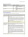
Configuration files
NMS OAM uses two types of configuration files:
File type
Description
System
configuration
Contains a list of boards in the system and the name of one or more
board keyword files for each board.
Board keyword
Contains parameters to configure the board. These settings are
expressed as keyword name and value pairs.
Several sample board keyword files are installed with Natural Access. You can reference
these files in your system configuration file or modify them.
When you run oamsys, it creates NMS OAM database records based on the contents of the
specified system configuration file and board keyword files. oamsys directs NMS OAM to
start the boards and configure them according to the specified parameters.
Refer to Configuring and starting the system using oamsys for more information.
CDI service
The CX Devices Interface (CDI) service is a Natural Access service that performs low-level
station-oriented call control and board management functions for CX boards. These
functions include tone generation, DTMF detection, signaling, on-board timer actuation,
temperature monitoring, power detection, and station module detection.
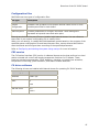
CX driver software
The following drivers are installed with Natural Access for operating CX 2000C boards:
Operating system Driver names
Windows
cxddrv.sys
UNIX
cx
cxsw
Red Hat Linux
cx.o
cxsw.o
15
Dialogic® CX 2000C Station Interface Board Installation and Developer's Manual
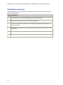
Installation summary
The following table summarizes the steps required to install CX 2000C hardware and
software components:
Step Description
1
Ensure that your PC system meets the system requirements.
2
Install the board and connect it to station telephones.
3
Connect a power supply. Refer to the Connecting a power supply section for
more information.
4
Install Natural Access. Refer to the Natural Access installation booklet for more
information.
5
Configure the system.
6
Verify that your installation is operational.
16
3.
Installing a CX 2000C board
System requirements
To install and use CX 2000C boards, your system must have:
•
Natural Access installed.
•
An uninterruptable power supply (UPS). Although a UPS is not strictly required, it is
strongly recommended for increased system reliability. The UPS does not need to
power the PC video monitor except in areas prone to severe lightning storms.
•
A CompactPCI chassis with an H.110 compliant telephony backplane with an
available CompactPCI bus slot. For more information about chassis, refer to Selecting
a CompactPCI chassis.
Note: The CX 2000C board will power up and function only in a chassis with a
telephony backplane.
•
A protective earth connection (required by UL and CSA safety approval). A grounded
lug must be provided on the chassis. The lug must be connected to a permanent
ground such as a metal water pipe.
•
A power supply. For more information, refer to Using the NMS rack mount power
supply chassis or Using an alternative power supply.
Caution: Each CX board is shipped in a protective anti-static container. Leave the board
in its original container until you are ready to install it. Handle the board
carefully and hold it only by its handles. We recommend that you wear an antistatic wrist strap connected to a good earth ground whenever you handle the
board.
17
Dialogic® CX 2000C Station Interface Board Installation and Developer's Manual
Selecting a CompactPCI chassis
Use the following guidelines when choosing a CompactPCI chassis:
•
The chassis must have high enough air flow to cool the CX 2000C. If the chassis
manufacturer specifies air flow, the air flow rating must provide at least 200 linear
feet per minute per slot of room temperature air.
If an air flow rating is not specified, use one fan with a rating of at least 50 cubic feet
per minute (CFM) for every four CX 2000C boards. There should be no preheating of
the air before cooling the CX 2000C board.
•
The chassis must have provisions for a protective grounding lug to maintain UL, CSA,
and EN 60950 certifications.
•
The chassis must have a telephony backplane with H.110 bus support.
•
Ideally, the chassis contains busses to distribute power from the ringing power
supply to the boards. Busses reduce the amount of cabling required. Six distribution
busses across the backplane are needed, rated as shown in this table:
Chassis connection
Chassis backplane current per board
-V bat
1A
V bat Rtn
1A
SELVbat
1A
SELVbatRtn
1A
VRG
0.250A
VRGRtn
0.250A
NMS supplies a cable to connect a power supply to a chassis with a telecom power
bus. One end of the cable has spade lugs to connect to the chassis. To learn more
about connecting power in this way, refer to Using the NMS rack mount power supply
chassis.
18
•
If you install an uninterrupted power supply and use it to back up the NMS rack
mount power supply (described in Using the NMS rack mount power supply chassis),
it should be rated for at least 1.8 kW.
•
Hot Swap support is recommended as a chassis and host CPU feature.
•
To allow insertion of the rear I/O transition board, the chassis must have the rear
I/O connector alignment feature. Some older CompactPCI chassis do not have this
feature. Contact the chassis manufacturer to find out if your chassis supports this
rear alignment feature.
•
Early CompactPCI chassis without alignment pins are not supported.
•
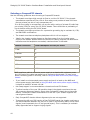
To support the 48 port, PBX version of the CX 2000C board, the chassis must have a
500 Vdc breakdown between the pins on J3 listed in the following table, and all other
signals (most importantly the +5 and ground layers). This is necessary to maintain
safety approvals and to support ringing signals.
Installing a CX 2000C board
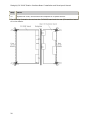
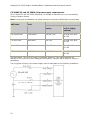
The following table shows the pins requiring clearance for J3/P3:
Pos# RowZ RowA RowB RowC RowD RowE RowF
19
18
T33
17
R33
T39
T44
16
T34
R39
R44
15
R34
T40
T45
14
T35
R40
R45
13
R35
T41
T46
12
T36
R41
R46
11
R36
T42
T47
10
T37
R42
R47
9
R37
T43
T48
8
T38
R43
R48
7
R38
6
5
4
RING2
3
2
1
19
Dialogic® CX 2000C Station Interface Board Installation and Developer's Manual
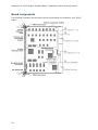
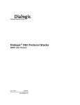
Board components
The following illustration shows where various components are located on a CX 2000C
board:
20
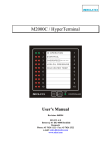
Installing a CX 2000C board
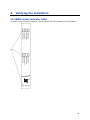
The following illustration shows where various components are located on the CX 2000C
rear I/O transition board:
21
Dialogic® CX 2000C Station Interface Board Installation and Developer's Manual
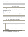
Configuring the internal ringer unit
A CX 2000C-32-R board includes an internal ringer unit: circuitry that can ring a limited
number of telephones based on chassis power. This board can ring 12 telephones with a
ringer equivalence of 1.0 at one time. Cable length is limited to 3000 feet.
The internal ringer unit circuitry is located on the CX 2000C-32-R rear I/O transition board.
If your board contains an internal ringer unit, you must select the ringing frequency. On the
rear I/O transition board, switches 3 and 4 on DIP switch S1 control the ringing frequency.
Set the switches as shown in the following table:
For a ringing frequency
setting of...
Set S1 switches 3 and 4 (rear I/O transition
board) to the following settings...
Switch 3
Switch 4
20 Hz (default)
OFF
OFF
16.7 Hz
OFF
ON
25 Hz
ON
OFF
50 Hz
ON
ON
On the rear I/O transition board, switches 1 and 2 on DIP switch S1 control other ringer
configuration options. These settings are preset.
DIP switch S1
(rear I/O transition
board)
Description
1
Ringer enabled (default). Set to ON if the internal ringer unit
is present on the board.
2
Battery return to ground. Must always be set to ON. Do not
change this setting.
Jumper pin block JP1 on the rear I/O transition board specifies the source of the ring
voltage:
JP1 setting
(rear I/O transition board)
Description
Jumper on pins 1 and 2
Ring voltage comes from the internal ringer unit
circuitry.
Jumper on pins 2 and 3
Ring voltage comes from the external power connector
(J8).
22
Installing a CX 2000C board
Jumper pin block JP4 on the main board specifies whether ring voltage is coming from the
rear I/O transition board or from the CompactPCI telecom power bus. For more information,
refer to Using the NMS rack mount power supply chassis.
JP4 setting (main
board)
Description
Jumper on pins 1 and 2
External ring voltage from rear transition board (default).
Jumper on pins 2 and 3
Ringing voltage from CompactPCI telecom power bus.
Grounding the chassis
Connect a permanent ground wire complying with international color code conventions
(green wire with a yellow stripe) from the permanent ground lug on the CompactPCI chassis
to a permanent earth grounding point within the building or facility. This should be done in
accordance with national electric code and local building code standards.
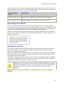
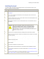
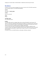
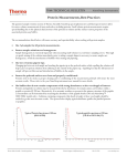
Attach the warning label supplied with the board or an equivalent label on the permanent
ground wire or near the ground stud on the CompactPCI chassis. The label is shown in the
following illustration:
Keying the chassis
A CX 2000C board has several mechanical interlocks, called keys, that prevent the board
from being inserted in a non-compatible chassis. Keying protects the board and other
devices in the chassis from damage.
Before you install CX 2000C boards, configure the keying of your chassis to be compatible
with the CX 2000C keying. This keying helps ensure that you do not accidentally insert an
incompatible board in the chassis.
This topic describes how to key the slots in your chassis for CX 2000C boards. For detailed
information on CompactPCI chassis keying, refer to the CompactPCI Computer Telephony
Specification PICMG 2.5 R1.0 and to the IEEE 1101.10.
Warning: To protect yourself and your equipment, allow only qualified personnel to
install keying. The personnel must be familiar with the CompactPCI Computer
Telephony Specification PICMG 2.5, R1.0 document. NMS is not responsible if
you install a board into a chassis where keying has not been properly
installed.
Note: A CX 2000C board will not function in a chassis that does not have a telephony
backplane.
23
Dialogic® CX 2000C Station Interface Board Installation and Developer's Manual
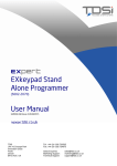
The following illustration shows how the CX 2000C board keys are configured:
24
Installing a CX 2000C board
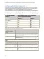
The following illustration shows the keying chambers in a CompactPCI chassis that you must
configure for a CX 2000C. You must also key rear panel keying chambers A through F that
are not shown.
Chambers A, D, E, and F are defined by backplane wiring and network signaling levels.
Chambers B and C are specific to the manufacturer.
25
Dialogic® CX 2000C Station Interface Board Installation and Developer's Manual
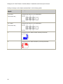
Configure keying in the chassis as described in the following table:
Keying chambers on
chassis
Configuration
A, B, and C
Configure as shown in this illustration:
(Front and rear)
D, E, and F
Configure as shown in this illustration:
(Front and rear)
J1
Configure with a male brilliant blue key as shown:
J4
Configure with a male strawberry red key as shown:
26
Installing a CX 2000C board
Installing the board
To initially install a CX 2000C board equipped with a rear I/O transition board in your
system, complete the following steps:
Step
Action
1
Make sure you have attached the permanent ground, as described in Grounding
the chassis.
2
Turn off the computer and disconnect it from the power source. Remove the
cover and set aside.
3
Choose a chassis slot for the CX 2000C board. Remove the access panels to the
chassis slot (both front and rear).
4
Verify that the chassis slot has the appropriate keying, as described in Keying
the chassis.
5
Slide the rear I/O transition board into a slot at the rear of the chassis.
Warning: Some older CompactPCI chassis may not have a rear I/O
connector alignment feature. The rear I/O transition board
requires this feature to allow insertion. Contact the chassis
manufacturer to find out if your chassis supports this rear
alignment feature. Use caution when inserting the board into the
backplane mating connector.
6
Seat the rear I/O transition board by rotating the top and bottom handles.
7
Fasten the rear I/O transition board to the chassis with the screws on the upper
and lower handles.
8
Slide the CX 2000C board into the corresponding slot in the front of the chassis.
9
Seat the CX 2000C board into the backplane by rotating the top and bottom
handles toward each other.
10
Fasten the CX 2000C board to the chassis with the screws on the upper and
lower handles.
11
Connect the computer to its power source.
12
Install Natural Access as described in the Natural Access installation booklet.
13
Connect station telephones to the board as described in Connecting to station
telephones.
14
Connect a power supply to the board as described in Using the NMS rack mount
power supply chassis or Using an alternative power supply.
27
Dialogic® CX 2000C Station Interface Board Installation and Developer's Manual
Step
Action
15
Replace the cover, and connect the computer to its power source.
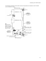
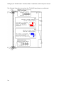
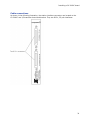
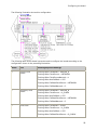
The following illustration shows how the CX 2000C board and the rear I/O transition board
sit in the chassis.
28
Installing a CX 2000C board
Connecting to station telephones
This topic describes how to connect station telephones or other devices to a CX 2000C
board:
•
Cabling considerations
•
Cable connections
•
Developer's cable kit
Warning: Important safety notes for telephony connections
•
Allow only qualified technical personnel to install this board and its
associated telephone wiring.
•
Never install telephone wiring during a lightning storm.
•
Safety regulations require that you properly ground the board by
connecting the ground stud on the chassis to a good earth ground.
•
If your site connects to private lines that leave the building, make sure
that external protection is provided.
Cabling considerations
When cabling your stations (especially off-premises stations), consider the following issues:
•
As the cable length increases, the DC resistance increases. Most telephones operate
correctly if the loop current is at least 20 mA. To maintain this minimum current, the
total cable resistance (the resistance on the tip wire plus the resistance on the ring
wire) must be less than 1500 Ohms over the expected temperature range. When
Telcordia guidelines are followed, the cable length cannot exceed 18,000 feet. If
these guidelines are exceeded, the attached device may not operate properly.
•
As the cable length increases, the cable presents an impedance to the audio path.
This attenuates the audio signals in both directions and creates an echo path.
Attempting to compensate for the loss by increasing gain will increase the echo and
other noise. The 18,000 foot cable limit also sets a limit of acceptable audio quality
for traditional telephony services. To improve the frequency response of the loop,
many telephone networks add a device called loading coils when subscriber loops
approach or exceed 18,000 feet. This can increase the echo.
•
Telephone networks offer services commonly called foreign exchange circuits. These
should be considered for applications requiring longer loops.
•
If any section of the wiring between the board and connected local telephone lines
runs outdoors or between buildings (buried or above ground), be sure to provide
adequate lightning protection.
29
Dialogic® CX 2000C Station Interface Board Installation and Developer's Manual
Warning: For lines that run between buildings, you or the approved installer must
provide primary protectors at the building service entrance point. These can
be carbon block or gas discharge protectors, but solid-state protectors are
recommended.
The NMS warranty does not cover damage by lightning or other electrical
discharge.
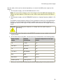
NMS recommends 24 AWG (0.6 mm) twisted pair cable for distances over 50 feet (15
meters). The following table lists the recommended cable types and maximum distances for
each:
Cable type
Recommended maximum distance
CX 2000C-32-R
All other CX 2000C
boards
24 AWG twisted pair
2000 feet
18 k feet (1500 Ohms
maximum)
0.6 mm twisted pair
700 meters
5.5 km (1500 Ohms
maximum)
30
Installing a CX 2000C board
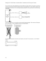
Cable connections
As shown in the following illustration, the station interface connectors are located on the
CX 2000C rear I/O transition board and bracket. They are RJ-21, 25-pair interfaces.
31
Dialogic® CX 2000C Station Interface Board Installation and Developer's Manual
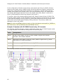
The connectors are each designed to accommodate a 25-pair cable. This cable is commonly
wired to a punch-down block or break-out box. The telephones or other station devices are
connected to the block or box through standard telephone wiring as shown in the following
illustration:
The RJ-21 connector on the cable must be the 180-degree design. The common 90 degree
RJ-21 connector is not compatible with the CX 2000C board.
The following illustration shows the pin locations for the RJ-21 connectors on a CX 2000C
board:
32
Installing a CX 2000C board
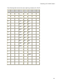
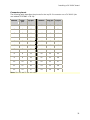
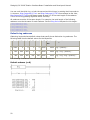
Connector pinout
The following table describes the pinouts for the top RJ-21 connector on a CX 2000C (the
one labeled STATIONS 1 TO 24):
Station
Ring
pin
Tip pin
Station
Ring pin
Tip pin
1
1
26
13
13
38
2
2
27
14
14
39
3
3
28
15
15
40
4
4
29
16
16
41
5
5
30
17
17
42
6
6
31
18
18
43
7
7
32
19
19
44
8
8
33
20
20
45
9
9
34
21
21
46
10
10
35
22
22
47
11
11
36
23
23
48
12
12
37
24
24
49
Note: Pins 25 and 50 are not used.
33
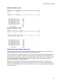
Dialogic® CX 2000C Station Interface Board Installation and Developer's Manual
The following table describes the pinouts for the bottom RJ-21 connector on a CX 2000C
(the one labeled STATIONS 25 TO 48):
Station
Ring
pin
Tip pin
Station
Ring pin
Tip pin
25
1
26
37
13
38
26
2
27
38
14
39
27
3
28
39
15
40
28
4
29
40
16
41
29
5
30
41
17
42
30
6
31
42
18
43
31
7
32
43
19
44
32
8
33
44
20
45
33
9
34
45
21
46
34
10
35
46
22
47
35
11
36
47
23
48
36
12
37
48
24
49
Note: Pins 25 and 50 are not used.
Developer's cable kit
NMS provides an optional developer's cable kit. The kit contains two 10 foot RJ-21 cables
and two breakout boxes. Each breakout box connects one RJ-21 to 24 standard RJ-11
(POTS) jacks for individual telephones. Use the cables to connect to the breakout boxes or
to standard 66 or 110 blocks.
All components of the developer's cable kit sold by NMS are also commercially available
from telephone product distributors such as Graybar and Anixter. These distributors can
provide variations in cable lengths.
34
4.
Connecting a power supply
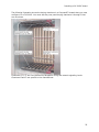
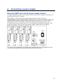
Using the NMS rack mount power supply chassis
To supply talk battery power to the station phones and to power ringing (if necessary), an
external power supply is required.
NMS supplies a rack mount power supply chassis that can contain up to four
interchangeable supply modules. Each module can power up to two CX 2000C boards. Four
modules produce a total combined output of 8.8 A for -48 V and -30 V/-24 V. The ring
output total is 0.68 A. The supply outputs are isolated from ground and rely on the
CX 2000C board to ground the return line. This provides the best EMI performance. The
following illustration shows a rack mount power supply chassis with four modules:
The power supply autoranges for global power standards and can be configured for local
ring frequency standards to satisfy global deployment requirements.
35
Dialogic® CX 2000C Station Interface Board Installation and Developer's Manual
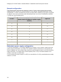
Normal configuration
The following table indicates the required number of power supply chassis and modules,
based upon the number of CX 2000C boards in your system. The table assumes a normal
configuration, in which all stations are active on each board. Sufficient ring signal is supplied
so that for short (not continuous) peak demand periods, more than 20 telephones rated at
1.0 REN can ring simultaneously.
Number of CX
boards
Power supply chassis required
(Each chassis includes one power supply
module)
Expansion modules
required
1
1
0
2
1
0
3
1
1
4
1
1
5
1
2
6
1
2
7
1
3
8
1
3
Redundant power supply configuration
To provide redundancy, or to supply additional ring power to your system, install one more
power supply module then you need. The module-to-board connectors on all modules are
wired in parallel, so if one module fails, another module supplies power to the first module's
board connector. This helps ensure uninterrupted power to any connected boards in the
unlikely event that a module fails.
If you connect the power supply to a UPS, the contribution of a fully populated power supply
chassis is 1.8 kW.
36
Connecting a power supply
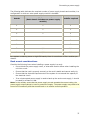
The following table indicates the required number of power supply chassis and modules, in a
configuration in which an extra power supply module is installed:
Number of CX
boards
Power supply chassis required
(Each chassis includes one power supply
module)
Expansion
modules required
1
1
1
2
1
1
3
1
2
4
1
2
5
1
3
6
1
3
7
N/A
N/A
8
N/A
N/A
In a system containing seven or eight CX boards, there is a maximum of four modules per
chassis.
Rack mount considerations
Consider the following items when installing a power supply in a rack:
•
Do not block the power supply vents, or otherwise restrict airflow when installing the
unit into a rack.
•
Ensure that the rack is properly secured, so the rack is stable and cannot easily tip.
•
Ensure that the electrical requirements of the system do not exceed the capacity of
the electrical circuit.
•
If an uninterrupted power supply is used to back up the rack mount supply, it should
be rated for at least 1.8 kW.
Note: In the unlikely event that the power supply current exceeds the current rating, the
power supply output clamps to zero to protect the supply. The power supply may need to be
turned off momentarily and then turned back on to restore normal operation.
37
Dialogic® CX 2000C Station Interface Board Installation and Developer's Manual
Connecting the NMS power supply
You can connect power supply modules directly to CX 2000C boards. Alternately, if you are
using a CompactPCI chassis whose backplane has a telecom power bus, you can use a
single cable to connect one of the modules to the bus. Since the modules are wired in
parallel, all power will reach the bus regardless of which module you physically connect.
NMS supplies two cables for these connections:
•
Shipped with the module - a cable with a male 8-pin Positronic connector on one end
(to connect to the module), and two 10-pin MOLEX mini junior connectors on the
other end to connect to the TELCO POWER connectors on CX 2000C boards.
•
Can be ordered separately - a cable with a male 8-pin Positronic connector on one
end (to connect to the module), and #8 spade lugs on the other end to connect to
the chassis telecom power bus.
Connecting directly to boards
To connect the NMS power supply directly to each board:
1. On the power supply chassis, set the VOLTAGE switch to 30 V.
2. On the power supply, set the FREQUENCY switch to a ringing frequency (default = 20
Hz).
The default ringing frequency setting (20 Hz) operates correctly for most applications.
However, you can change this setting if a station does not ring when directed, or to
change the sound of the ringer to match that of other devices in the target country or
region.
Warning: Do not change the frequency or voltage while the power supply is
operating.
3. Plug the Y end of the cable into the TELCO POWER connectors on the CX 2000C
boards. This connector is located on the rear transition board.
4. Plug the other end of the cable into the power supply.
5. When you have finished configuring the power supply, plug it into a power source.
Connecting to a CompactPCI chassis telecom power bus
If your CompactPCI chassis contains busses to distribute power from the ringing power
supply to the boards, you can connect the NMS power supply directly to the chassis instead
of to each board. This reduces the amount of cabling required.
Six distribution busses across the backplane are needed: Vbat, VbatRtn, SELVbat,
SELVbatRtn, VRG, and VRGRtn. These busses must be rated for a minimum of 1 A per
CX 2000C board. The cable interface to the bus should be lugs on the bus.
38
Connecting a power supply
Use the cable, which can be ordered separately, to connect the NMS power supply to the
chassis:
1. On the power supply, set the VOLTAGE switch to 30 V.
Note: You can set the voltage to 24 V if the length of the 24 AWG cable between the
system and each station is 2000 feet or less, with a total resistive load of 600 Ohms
or less.
2. On the power supply, set the FREQUENCY switch to a ringing frequency (default = 20
Hz).
The default ringing frequency setting (20 Hz) operates correctly for most applications.
However, you can change this setting if a station does not ring when directed, or to
change the sound of the ringer to match that of other devices in the target country or
region.
Warning: Do not change the frequency or voltage while the power supply is
operating.
3. Connect one end of the cable to the OUTPUTS connector on any module in the power
supply chassis.
4. At the other end of the cable, connect each wire as described in the following table:
Power supply
output
Chassis
connection
Chassis backplane current per
board
-48
-V bat
1A
-48 return
V bat Rtn
1A
-30
SELVbat
1A
-30 return
SELVbatRtn
1A
Ring
VRG
.250 A
Ring return
VRGRtn
.250 A
Chassis ground
Frame ground
5. When you have finished configuring the power supply, plug it into a power source.
39
Dialogic® CX 2000C Station Interface Board Installation and Developer's Manual
Alarm signal connector
The NMS rack mount power supply has a DB9 connector on the rear panel that can be used
to indicate an alarm condition. The following table lists the pinouts of this connector:
Pin
Description
1
Chassis ground
2
1.5K resistor to +12 V DC
3
4.7K resistor to +5 V DC
4
Alarm signal output. This is an open collector NPN transistor with the emitter
connected to COMMON. The transistor is normally on. It is turned off for an alarm
condition. The transistor is rated for 20 V DC and 5 mA. The 4.7K resistor on pin 3
or pin 7 can provide pull-up to +5 V DC.
5
Optional signal
6
+5 V DC @ 3 mA
7
4.7 K resistor to +5 V DC
8
COMMON
9
COMMON
Powering up the power supply
To power up the supply, turn on the POWER ON switch located on the rear panel of the unit.
When the unit is operating properly, the green POWER ON indicator on the front panel
glows. In addition, the POWER ON indicator on each module glows (visible on the rear panel
of the unit).
40
Connecting a power supply
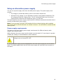
Using an alternative power supply
You can use a power supply other than the NMS power supply. This power supply must
provide:
•
DC voltage to provide talk battery power to the station telephones.
•
AC and DC ring voltage, if your application involves ringing station telephones. The
AC voltage provides the ringing power. The DC voltage provides loop current that
signals the CX board when the telephone goes on or off hook.
This topic specifies the power supply requirements for different boards and describes how to
connect an alternative power supply.
Note: If you are using CX 2000C-32-R boards with the on-board ringing option enabled,
you do not need to provide external ring voltage. However, you still need to provide the talk
battery power.
Power supply requirements
The tables in this topic specify power supply requirements for different boards, cable
lengths, and resistive loads.
Cables between the power supply and the board must be rated for 2 A per board or greater.
Twisted pair cabling is recommended for noise reduction.
Warning: In the worst case, the ring voltage must not exceed 92 V AC, and the DC
voltage must not exceed 52 V DC.
An AG 2000 power supply can be substituted for the rack mount supply for one CX 2000C
board. The cable supplied with the AG 2000 power supply will mate with the connector on
the board.
41
Dialogic® CX 2000C Station Interface Board Installation and Developer's Manual
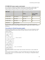
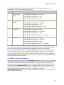
CX 2000C-32 and CX 2000C-48 power supply requirements
For CX 2000C-32 and CX 2000C-48 boards, AC voltage is required only if you are enabling
ringing of station phones.
Note: In this type of installation, all cables must be a minimum of 8000 feet to control heat.
Length of 24
AWG cable
Maximum resistive
load
Recommended output
Talk
battery
Ring voltage
(only if ringing
required)
0 to 18,000 feet
1500 Ohms
-30/-48 V DC
80 to 89 V AC and 48 V DC
0 to 2000 feet
600 Ohms
-24 V DC
55 to 89 V AC and 24 V DC
0 to 8000 feet
800 Ohms
-30 V DC
55 to 89 V AC and 30 V DC
8000 to 18,000 feet
1500 Ohms
-48 V DC
80 to 89 V AC and 48 V DC
The dual output -30/-48 V DC supply is preferred. However, if the cable lengths to all
stations fit into one of the other categories listed above, a supply with a single DC output is
satisfactory.
The ring signal circuitry in the power supply must be equivalent to the following illustration:
42
Connecting a power supply
CX 2000C-32-R power supply requirements
For CX 2000C-32-R boards, AC voltage is required only if you want to enable ringing, and
are not using the on-board ringer option. In this case, CX 2000C-32-R power supply
requirements are identical to those of the CX 2000C-32 and CX 2000C-48.
Length of 24
AWG cable
Max resistive load
Recommended output
Talk
battery
Ring voltage
(only if ringing
required)
0 to 8000 feet
1500 Ohms
-30/-48 V DC
N/A
0 to 2000 feet
600 Ohms
-24 V DC
N/A
0 to 8000 feet
800 Ohms
-30 V DC
N/A
> 8000 feet
Not supported.
The dual output -30/-48 V DC supply is preferred. However, if the cable lengths to all
stations fit into one of the other categories listed above, a supply with a single DC output is
satisfactory.
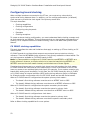
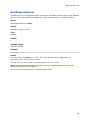
Connecting an alternative power supply
Connect the power supply to the TELCO POWER connector on the rear I/O transition board.
The following illustration shows the power connector pinouts for the CX 2000C (rear I/O
transition board):
The mating connector is Molex 43025-1000 with Molex 43030-0001 or Molex 43030-007
pins.
If only one DC output is available, it must be connected to both the high battery input and
the low battery input. For more information, refer to Connecting to a CompactPCI chassis
telecom power bus.
43
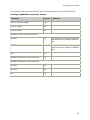
5.
Configuring the board
Referencing the CDI manager for Natural Access
For the CDI manager component to be available to the Natural Access server when it boots,
the CDI manager must be referenced in the Natural Access configuration file, cta.cfg, as
shown below:
[ctasys]
Service =
Service =
Service =
Service =
Service =
Service =
Service =
Service =
Service =
ncc,
adi,
cdi,
ais,
dtm,
ppx,
swi,
vce,
oam,
adimgr
adimgr
cdimgr
aismgr
adimgr
ppxmgr
swimgr
vcemgr
oammgr
For more information about cta.cfg and its contents, refer to the Natural Access Developer's
Reference Manual.
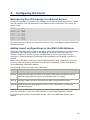
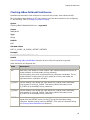
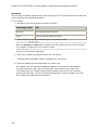
Adding board configurations to the NMS OAM database
Each board that NMS OAM configures and starts must have a separate set of configuration
parameters. Each parameter value is expressed as a keyword name/value pair (for
example, Encoding = MuLaw). You can use NMS OAM to retrieve parameters for any
component. These parameters (set through board keywords) can be added, modified, or
deleted.
Before using NMS OAM, make sure that the Natural Access Server (ctdaemon) is running.
For more information about the Natural Access Server (ctdaemon), refer to the Natural
Access Developer's Reference Manual.
The following utilities are shipped with NMS OAM:
Utility
Description
oamsys
Configures and starts up boards on a system-wide basis. Attempts to start all
specified boards based on system configuration files you supply.
oamcfg
Provides greater access to individual NMS OAM configuration functions.
oaminfo Displays keywords and settings for one or more components. Can also set
individual keywords.
Applications can use OAM service functions to retrieve and modify configuration parameters.
For more information, refer to the NMS OAM Service Developer's Reference Manual.
For general documentation of NMS OAM utilities, refer to the NMS OAM System User's
Manual.
44
Configuring the board
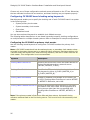
Configuring and starting the system using oamsys
To configure a system using oamsys:
Step
Action
1
Install the boards as described in the section Installing a CX 2000C board.
2
Determine which board keyword file you will use, or edit one of the sample CX
2000 board keyword files, to specify appropriate configuration information for
each board. For more information, refer to Using keywords.
3
Determine the PCI bus and slot locations of the boards, using the pciscan utility.
pciscan identifies the NMS PCI boards installed in the system and returns each
board's bus, slot, interrupt, and board type. For more information about pciscan,
refer to the NMS OAM System User's Manual.
4
Create a system configuration file, or edit a sample system configuration file, to
point to all the board keyword files for your system. Specify a unique name and
board number for each board. A sample system configuration file is provided.
5
Start oammon to monitor the NMS OAM system and all NMS boards. For more
information about oammon, refer to the NMS OAM System User's Manual.
Start oammon before running oamsys. Keep oammon running to see the status
of all boards in your system and to view error and tracing messages.
6
Use oamsys to start all the installed boards (ctdaemon must be running when
you use oamsys) according to the configuration information specified in the
system configuration file and any associated board keyword files. For more
information, refer to Running oamsys.
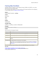
Creating a system configuration file for oamsys
Create a system configuration file describing all of the boards in your system. oamsys
creates records, and then directs NMS OAM to start the boards, configured as specified. The
system configuration file is typically named oamsys.cfg. By default, oamsys looks for a file
with this name when it starts up. Refer to the NMS OAM System User's Manual for specific
information about the syntax and structure of this file.
Note: You can use the oamgen utility (included with the NMS OAM software) to create a
sample system configuration file for your system. The system configuration file created by
oamgen may not be appropriate for your configuration. You may need to make further
modifications to the file before running oamsys to configure your boards based on the file.
For more information about oamgen, refer to the NMS OAM System User's Manual.
45
Dialogic® CX 2000C Station Interface Board Installation and Developer's Manual
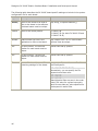
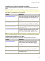
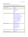
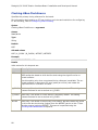
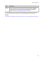
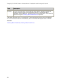
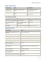
The following table describes the CX 2000C board-specific settings to include in the system
configuration file for each board:
Keyword Description
Allowed values for CX 2000C products
[name]
Name of the board to be used to
refer to the board in the software.
The board name must be unique.
Any string, in square brackets [].
Product
Name of the board product.
CX 2000C-48
CX 2000C-32 (for both CX 2000C-32 and
CX 2000C-32-R)
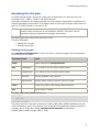
Number
Board number you use in the
application to refer to the board.
Any integer from 0 to 31. Each board's
number must be unique.
Bus
PCI bus number. The bus:slot
location for each board must be
unique.
Values returned by pciscan.
Slot
PCI slot number. The bus:slot
location for each board must be
unique.
Values returned by pciscan.
File
Name of the board keyword file
containing settings for the board.
You can specify more than one file after
the File keyword:
File = mya.cfg myb.cfg myc.cfg
Alternatively, you can specify the File
keyword more than once:
File = mya.cfg
File = myb.cfg
File = myc.cfg
Board keyword files are sent in the order
listed. The value for a given keyword in
each file overrides any value specified for
the keyword in earlier files.
46
Configuring the board
Sample system configuration file
The following system configuration file describes two CX 2000C boards:
•
Board number 0 is located at bus 0, slot 15. It is assigned a keyword file named cxmaster.cfg.
•
Board number 1 is located at bus 0, slot 16. It is assigned a keyword file named cxslave.cfg.
•
[CX-0]
Product
Number
Bus
Slot
File
=
=
=
=
=
CX 2000C-48
0
0
15
c:\nms\cx\cfg\cx-master.cfg
[CX-1]
Product
Number
Bus
Slot
File
=
=
=
=
=
CX 2000C-32
1
0
16
c:\nms\cx\cfg\cx-slave.cfg
Running oamsys
To run oamsys, enter the following command:
oamsys -f filename
where filename is the name of an NMS OAM system configuration file.
Note: If you invoke oamsys without command line options, NMS OAM searches for a file
named oamsys.cfg in the paths specified in the AGLOAD environment variable.
When you invoke oamsys with a valid file name, oamsys performs the following tasks:
•
Checks the syntax of the system configuration file to make sure that all required
keywords are present. oamsys discards any unrecognized keywords and reports any
syntax errors it finds. oamsys verifies the file syntax of system configuration files,
but not of board keyword files.
•
Checks for uniqueness of board names, board numbers, and board bus and slot
numbers.
•
Shuts down all boards recognized by NMS OAM (if any).
•
Deletes all board configuration information currently maintained for the recognized
boards (if any).
•
Sets up the NMS OAM database and creates all records as described in the system
configuration file.
•
Attempts to start all boards as specified in the system configuration file and the
board keyword files it references.
The Natural Access Server (ctdaemon) must be running for oamsys to operate. For more
information about the Natural Access Server, refer to the Natural Access Developer's
Reference Manual.
47
Dialogic® CX 2000C Station Interface Board Installation and Developer's Manual
Changing configuration parameter settings
When you run oamsys, the utility starts all boards according to the configuration parameters
specified in their associated board keyword files.
Specify parameters in board keyword files as name/value pairs such as AutoStart = NO.
To change a parameter:
•
Use or modify one of the sample board keyword files corresponding to your country
and board type. Refer to the NMS OAM System User's Manual for information about
the syntax of NMS OAM board keyword files.
•
Specify parameter settings using the oamcfg utility. Refer to the NMS OAM System
User's Manual for information about oamcfg.
•
Create a new board keyword file either with additional keywords or with keywords
whose values override earlier settings.
•
Specify the settings using the OAM service functions. Refer to the NMS OAM Service
Developer's Reference Manual for more information.
A sample board keyword file, cx2000.cfg, is installed by Natural Access. You can copy this
file and modify it. The file is located in one of the following paths, depending upon your
operating system:
Operating system
Path to cx2000.cfg
Windows
\nms\cx\cfg
UNIX
/opt/nms/cx/cfg
The contents of cx2000.cfg are shown in the following example. For information about NMS
OAM board keyword files, refer to the NMS OAM System User's Manual.
#
# Standalone operation
#
Clocking.HBus.ClockMode
= STANDALONE
Clocking.HBus.ClockSource = OSC
#
# Master the CT Bus (drive clock A)
#
#Clocking.HBus.ClockMode
= MASTER_A
#Clocking.HBus.ClockSource = OSC
#
# Slave to the CT Bus (slave from clock A)
#
#Clocking.HBus.ClockMode
= SLAVE
#Clocking.HBus.ClockSource = A_CLOCK
You can customize additional features:
48
•
Configuring ring cadences
•
Configuring board clocking
Configuring the board
Configuring ring cadences
For CX 2000C boards, you can specify up to three different ring patterns (cadences) to use
at different times. For example, you can configure one cadence to signify an extension-toextension call, another cadence to signify an outside call, and another cadence to signify a
callback.
Each cadence can have up to three rings per cycle. For example, your first cadence could
consist of one 2000 ms ring followed by 4000 ms of silence (like a typical ring tone in the
United States). Your second cadence could sound more like the ring tone in the UK (ring
ring...ring ring...). Your third cadence could have three rings (ring ring ring...ring ring
ring...).
Ring cadencing is controlled with board keywords. Cadencing keywords have default values
that specify three distinctive ring cadences. The following keywords determine each
cadence:
Keyword
Description
Ring.Cadences[x].Ton1 Determines the length (in ms) of the first ring in the cadence.
Ring.Cadences[x].Toff1 Determines the length (in ms) of the silence between the first
and second rings in the cadence.
Ring.Cadences[x].Ton2 Determines the length (in ms) of the second ring in the cadence.
Ring.Cadences[x].Toff2 Determines the length (in ms) of the silence between the second
and last rings in the cadence.
Ring.Cadences[x].Ton3 Determines the length (in ms) of the last ring in the cadence.
Ring.Cadences[x].Toff3 Determines the length (in ms) of the silence between the last
ring in the cadence and the first ring of the next cadence. This
value must be equal to 2/3 of the total length of the cadence.
Ring.Period
Must be set to the total length of the cadence (in ms).
The following illustration shows the role of each keyword in determining a cadence:
49
Dialogic® CX 2000C Station Interface Board Installation and Developer's Manual
You can omit the third ring, or both the second and third rings, by setting their keywords to
0. However, Ring.Cadences[x].Ton1 and Ring.Cadences[x].Toff3 must always be set. Also,
Ring.Cadences[x].Toff3 must always equal at least 2/3 of the total length of the cadence.
This is so the ring phasing algorithm works correctly.
All cadences must be of the same length. For example, the total length of the following
cadences must be the same for each cadence. Set the Ring.Period keyword to this length.
+
+
+
+
+
Ring.Cadences[x].Ton1
Ring.Cadences[x].Toff1
Ring.Cadences[x].Ton2
Ring.Cadences[x].Toff2
Ring.Cadences[x].Ton3
Ring.Cadences[x].Toff3
Default ring cadences
Cadencing keywords have default values that specify three distinctive ring cadences. The
following table lists the default values for the keywords:
x
Ton1 Toff1 Ton2 Toff2 Ton3 Toff3 Total
ms
Ring pattern
0
2000
0
0
0
0
4000
6000 ring...(silence)...
1
600
800
600
0
0
4000
6000 ring...ring...(silence)...
2
400
400
400
400
400
4000
6000 ring...ring...ring...(silence)...
The following illustrations show the three default cadences.
Default cadence (x=0)
50
Configuring the board
Default cadence (x=1)
Default cadence (x=2)
Using the Hot Swap features
Hot Swap functionality is an integral part of NMS OAM. It is designed for use with the CX
2000C boards and is supported on Windows and UNIX systems.
The CX 2000C board includes a switch built into the ejector handle and an end bracket Hot
Swap LED. When you insert a board into the system, the switch signals that the board is
fully seated with the handle closed and that the software connection can be initiated. When
you remove a board, the switch signals that the board is being extracted and that the
software disconnection can be initiated.
When lit, the Hot Swap LED indicates that the software disconnection is complete and
extraction is permitted. You can open the handle the rest of the way and eject the board.
Refer to the NMS OAM System User's Manual for information on configuring and starting the
Hot Swap process.
51
Dialogic® CX 2000C Station Interface Board Installation and Developer's Manual
Configuring board clocking
When multiple boards are connected to the CT bus, you must set up a bus clock to
synchronize timing between them. In addition, you can configure alternative (or fallback)
clock sources to provide the clock signal if the primary source fails.
This topic describes:
•
Clocking capabilities
•
Clocking configurations
•
Configuring using keywords
•
Examples
•
Clocking exceptions
To create a robust clocking configuration, you must understand basic clocking concepts such
as clock mastering and fallback. This topic assumes that you have a basic understanding of
clocking. For a complete overview of board clocking, refer to the NMS OAM System User's
Manual.
CX 2000C clocking capabilities
This topic describes the rules and limitations that apply to setting up CT bus clocking on CX
2000C boards.
CX 2000C boards do not have direct access to any external source to derive a timing
reference. Thus the NETWORK timing reference is not directly available to these boards. The
only timing source available to CX 2000C boards is OSC.
Note: It is also possible to configure a CX 2000C board to use NETREF1 or NETREF2 as a
timing reference. However, a simpler solution is to have the board driving NETREF1 or
NETREF2 serve as the clock master instead, and eliminate use of these signals.
If another board has access to an outside clock signal, use this board as the clock master.
CX 2000C boards are best used as clock masters only if none of the boards on the CT bus
have any access to an outside digital clock signal (for example, if your system contains only
boards with analog trunk interfaces). In this case, the CX 2000C board can drive A_CLOCK
or B_CLOCK using its internal oscillator (OSC) as the timing reference. Refer to Examples
for a sample system configuration with one CX 2000C board and two AG Series boards.
When a CX 2000C board is configured as the system primary clock master:
•
The board's first timing reference must be set to a NETREF clock or OSC.
•
The board's fallback timing reference must be set to a NETREF reference or OSC.
When a CX 2000C board is configured as the system secondary clock master:
•
The board's first timing reference must be the system's primary clock.
•
The board's fallback timing reference must be set to a NETREF source or OSC.
When a CX 2000C board is configured as a clock slave:
•
The board's first timing reference must be the system's primary clock.
•
The board's fallback timing reference must be the system's secondary clock.
Refer to Other clocking capabilities for more options.
52
Configuring the board
The following tables summarize the CT bus clocking capabilities of the CX 2000C board:
Clocking capabilities as primary master
Capability
Yes/No
Serve as primary master
Yes
Drive A_CLOCK
Yes
Drive B_CLOCK
Yes
Comments
Available primary timing references:
NETREF1
Yes
The application must reconfigure the
board as soon as possible if NETREF1
fails.
NETREF2
Yes
The application must reconfigure the
board as soon as possible if NETREF2
fails.
OSC
Yes
Fallback to secondary timing reference
Yes
Available secondary timing references:
NETREF1
Yes
NETREF2
Yes
OSC
Yes
53
Dialogic® CX 2000C Station Interface Board Installation and Developer's Manual
Clocking capabilities as secondary master
Capability
Yes/No
Comments
Serve as secondary master
Yes
Drive A_CLOCK
Yes
If the primary master drives
B_CLOCK, the secondary master
drives A_CLOCK.
Drive B_CLOCK
Yes
If the primary master drives
A_CLOCK, the secondary master
drives B_CLOCK.
Available secondary timing references:
NETREF1
Yes
NETREF2
Yes
OSC
Yes
Clocking capabilities as slave
Capability
Yes/No
Serve as slave
Yes
Slave to A_CLOCK
Yes
Slave to B_CLOCK
Yes
Available fallback timing references:
A_CLOCK
Yes
B_CLOCK
Yes
54
Comments
Configuring the board
Other clocking capabilities
Capability
Yes/No
Comments
Drive NETREF1
Yes
This board can drive either
NETREF1 or NETREF2, but not both
at once.
Drive NETREF2
Yes
This board can drive either
NETREF1 or NETREF2, but not both
at once.
Operate in standalone mode
Yes
Clocking configurations
You can configure board clocking in your system in one of two ways:
Method
Description
Using clockdemo
application model
Create an application that assigns each board its clocking mode,
monitors clocking changes, and reconfigures clocking if clock
fallback occurs.
A sample clocking application, clockdemo, is provided with Natural
Access. clockdemo provides a robust fallback scheme that suits most
system configurations. clockdemo source code is included, allowing
you to modify the program if your clocking configuration is complex.
For more information about clockdemo, refer to the NMS OAM
System User's Manual.
Note: Most clocking applications (including clockdemo) require all
boards on the CT bus to be started in standalone mode.
Using board
keywords (with or
without application
intervention)
For each board on the CT bus, set the board keywords to determine
the board's clocking mode and to determine how each board
behaves if clock fallback occurs.
This method is documented in this topic. Unlike the clockdemo
application, which allows you to specify several boards to take over
mastery of the clock when another board fails, the board keyword
method allows you to specify only a single secondary master. For
this reason, the board keyword method is best used to implement
clock fallback in your system, or in test configurations where clock
reliability is not a factor.
The board keyword method does not create an autonomous clock
timing environment. If you implement clock fallback using this
method, an application must still intervene when clock fallback
occurs to reset system clocking before other clocking changes occur.
If both the primary and secondary clock masters stop driving the
clocks, and an application does not intervene, the boards default to
standalone mode.
55
Dialogic® CX 2000C Station Interface Board Installation and Developer's Manual
Choose only one of these configuration methods across all boards on the CT bus. Otherwise,
the two methods interfere with one another, and board clocking may not operate properly.
Configuring CX 2000C board clocking using keywords
Board keywords enable you to specify the clocking role of each CX 2000C board in a system
in the following ways:
•
System primary clock master
•
System secondary clock master
•
Clock slave
•
Standalone board
You can also use board keywords to establish clock fallback sources.
The following tables describe how to use board keywords to specify clocking configurations
on multiple-board or multiple-chassis systems. Refer to Examples for sample configurations.
Configuring the CX 2000C as primary clock master
Use the following board keywords to configure a CX 2000C board as the primary clock
master.
Note: A CX 2000C board should not be used as primary or secondary clock master unless
no board in the system has access to an external timing reference. Use these settings only
if another board has access to an external timing reference, and the CX board must act as
clock master. This configuration is not recommended.
Keyword
Description
Clocking.HBus.ClockSource
Specifies the source from which this board derives its
timing. Set this keyword to a network source
(NETREF, NETREF2, or OSC).
Clocking.HBus.ClockMode
Specifies the CT bus clock that the board drives. Set
this keyword to either A_CLOCK (MASTER_A) or
B_CLOCK (MASTER_B).
Clocking.HBus.AutoFallBack
Enables or disables clock fallback on the board. Set
to YES if Clocking.HBus.ClockSource is set to NETREF
or NETREF2. Otherwise, set to NO.
Clocking.HBus.FallbackClockSource Specifies an alternate timing reference to use when
the master clock source fails. Set this keyword to a
timing source other than the one specified with
Clocking.HBus.ClockSource: NETREF, NETREF2, or
OSC.
Note: If the primary master's first source fails and then returns, the board's timing
reference switches back to the first timing source. This is not true for the secondary clock
master.
56
Configuring the board
Configuring the CX 2000C as secondary clock master
Use the following board keywords to configure a CX 2000C board as the secondary clock
master.
Note: A CX 2000C should not be used as primary or secondary clock master unless no
board in the system has access to an external timing reference. Use these settings only if
another board has access to an external timing reference, and the CX board must act as
clock master. This configuration is not recommended.
Keyword
Description
Clocking.HBus.ClockSource
Specifies the source from which this board derives its
timing. Set this keyword to the clock driven by the
primary clock master. For example, if the primary
master drives A_CLOCK, set the keyword to
A_CLOCK.
Clocking.HBus.ClockMode
Specifies the CT bus clock that the secondary master
drives. Set this keyword to the clock not driven by
the primary clock master (MASTER_A or MASTER_B).
Clocking.HBus.AutoFallBack
Enables or disables clock fallback on the board. Set
this keyword to YES.
Clocking.HBus.FallbackClockSource Specifies an alternate timing reference to use when
the master clock does not function properly. Set this
keyword to a timing reference not used by the
primary clock master: NETREF, NETREF2, or OSC.
Note: If the primary master's timing reference recovers, the secondary master continues to
drive the clock referenced by all clock slaves in the system until the application intervenes.
Configuring the CX 2000C as a clock slave
Use the following board keywords to configure a CX 2000C board as a clock slave:
Keyword
Description
Clocking.HBus.ClockMode
Specifies the CT bus clock from which the board
derives its timing. Set this keyword to SLAVE to
indicate that the board does not drive any CT bus
clock (although the board can still drive NETREF or
NETREF2).
Clocking.HBus.ClockSource
Specifies the source from which this clock derives its
timing. Set this keyword to the clock driven by the
primary clock master (A_CLOCK or B_CLOCK).
Clocking.HBus.AutoFallBack
Enables or disables clock fallback on the board. Set
this keyword to YES.
57
Dialogic® CX 2000C Station Interface Board Installation and Developer's Manual
Keyword
Description
Clocking.HBus.FallbackClockSource Specifies the alternate clock reference to use when
the master clock does not function properly. Set this
keyword to the clock driven by the secondary clock
master (B_CLOCK or A_CLOCK).
Configuring the CX 2000C as a standalone board
To configure a CX 2000C board in standalone mode so the board references its own clocking
information, set Clocking.HBus.ClockMode to STANDALONE. In standalone mode, the board
uses only its own oscillator as a timing signal reference. However, the board cannot make
switch connections to the CT bus.
Examples
Example 1: System with mixed board types
The following example assumes a system configuration in which one CX 2000C board and
two AG Series boards reside in a single chassis. The boards are configured in the following
way:
Board
Configuration
Board 0
AG Series board. Primary bus master. Drives A_CLOCK, based on signal from
network (trunk 1). Falls back to signal from network (trunk 3).
Board 1
AG Series board. Secondary bus master. Drives B_CLOCK, based on signal
from A_CLOCK. Falls back to signal from network (trunk 2).
Board 2
CX 2000C board. Clock slave to A_CLOCK (auto-fallback enabled).
This configuration assigns the following clocking priorities:
Priority Timing reference
First
Board 0, digital trunk 1.
A network signal from a digital trunk provides the primary master clock source.
Second
Board 0, digital trunk 3.
A network signal from a digital trunk provides the primary master clock source.
Third
Board 1, digital trunk 2.
A network signal from a digital trunk provides the secondary master clock
fallback source.
When multiple boards are connected to the CT bus, you must set up a bus clock to
synchronize timing between them. In addition, you can configure alternative (or fallback)
clock sources to provide the clock signal if the primary source fails.
58
Configuring the board
The following illustration shows this configuration:
The following table shows board keywords used to configure the boards according to the
configuration shown in the preceding illustration:
Board
Role
Clocking keyword settings
0
Primary clock
master
Clocking.HBus.ClockMode = MASTER_A
Clocking.HBus.ClockSource = NETWORK
Clocking.HBus.ClockSourceNetwork = 1
Clocking.HBus.AutoFallBack = YES
Clocking.HBus.FallBackClockSource = NETWORK
Clocking.HBus.FallBackNetwork = 3
1
Secondary clock
master
Clocking.HBus.ClockMode = MASTER_B
Clocking.HBus.ClockSource = A_CLOCK
Clocking.HBus.AutoFallBack = YES
Clocking.HBus.FallBackClockSource = NETWORK
Clocking.HBus.FallBackNetwork = 2
2
Clock slave
Clocking.HBus.ClockMode = SLAVE
Clocking.HBus.ClockSource = A_CLOCK
Clocking.HBus.AutoFallBack = YES
Clocking.HBus.FallBackClockSource = B_CLOCK
59
Dialogic® CX 2000C Station Interface Board Installation and Developer's Manual
In this configuration, Board 0 is the primary clock master and drives A_CLOCK. All slave
boards on the system use A_CLOCK as their first timing reference. Board 0 references its
timing from a network timing signal received on its own trunk 1. Board 0 also uses the
network timing signal from its own trunk 3 as its clock fallback source. This means that if
the network timing signal derived from its own digital trunks fails, Board 0 continues to
drive A_CLOCK based on the timing reference from trunk 3.
If, however, both of the signals used by Board 0 fail, Board 0 stops driving A_CLOCK. The
secondary master (Board 1) then falls back to a timing reference received on its own trunk
2, and uses this signal to drive B_CLOCK. B_CLOCK then becomes the timing source for all
boards that use B_CLOCK as their backup timing reference. The primary master also
attempts to slave to B_CLOCK.
Note: For this clock fallback scheme to work, all the clock slaves must specify A_CLOCK as
the clock source, and B_CLOCK as the clock fallback source.
Example 2: System with CX 2000C boards only, CX is master
The following example assumes a system configuration where four CX 2000C boards reside
on a single chassis. The boards are configured in the following way:
Board
Configuration
Board 0
Primary clock master. Drives A_CLOCK, based on signal from internal
oscillator. Auto-fallback disabled.
Board 1
Secondary clock master. Drives B_CLOCK, based on signal from A_CLOCK.
Falls back to its internal oscillator.
Board 2
Clock slave to A_CLOCK. Falls back to B_CLOCK.
Board 3
Clock slave to A_CLOCK. Falls back to B_CLOCK.
The following illustration shows this configuration:
60
Configuring the board
The following table shows keywords used to configure the boards according to the
configuration shown in the preceding illustration:
Board
Role
Clocking keyword settings
0
Primary clock
master
Clocking.HBus.ClockMode = MASTER_A
Clocking.HBus.ClockSource = OSC
Clocking.HBus.AutoFallBack = NO
1
Secondary clock
master
Clocking.HBus.ClockMode = MASTER_B
Clocking.HBus.ClockSource = A_CLOCK
Clocking.HBus.AutoFallBack = YES
Clocking.HBus.FallBackClockSource = OSC
2
Clock slave
Clocking.HBus.ClockMode = SLAVE
Clocking.HBus.ClockSource = A_CLOCK
Clocking.HBus.AutoFallBack = YES
Clocking.HBus.FallBackClockSource = B_CLOCK
3
Clock slave
Clocking.HBus.ClockMode = SLAVE
Clocking.HBus.ClockSource = A_CLOCK
Clocking.HBus.AutoFallBack = YES
Clocking.HBus.FallBackClockSource = B_CLOCK
In this configuration, Board 0 is the primary master and drives A_CLOCK. All slave boards
on the system use A_CLOCK as their first timing reference. Board 0 references its timing
from a signal derived from its oscillator. Auto-fallback is disabled for this board.
Board 1 is the secondary master, driving B_CLOCK based on A_CLOCK. If Board 0 stops
driving A_CLOCK, Board 1 continues driving B_CLOCK based upon its internal oscillator.
All other boards are slaves to A_CLOCK. If Board 0 stops driving the clock, all boards fall
back to B_CLOCK, which is driven by Board 1. If Board 1 stops driving B_CLOCK, all boards
fall back to their internal oscillators.
CX 2000C clocking exceptions
Applications can poll clock status with swiGetBoardClock periodically to capture snapshots
of the board clock status and to detect clocking events, such as the loss of a source. While
most boards provide an instantaneous clock status, CX boards provide a latched clock
status, which locks in the clock status until it is cleared. When polling the clock status on a
CX 2000C board, swiGetBoardClock reports a status of BAD on each clock source that
experienced an error any time since the last configuration command was issued. To clear
the errors and refresh the status information, an application must call
swiConfigBoardClock. For information about using these functions, refer to the Switching
Service Developer's Manual.
61
Dialogic® CX 2000C Station Interface Board Installation and Developer's Manual
The sample swish script that follows shows a strategy for obtaining the most current clock
status:
#
#
Obtaining fresh clock status on CX 2000 boards.
#
#
When querying clocks on most boards, the query returns an
#
instantaneous clock status. CX 2000 is different in that it latches
#
clock errors when they occur. Errors remain latched until the next
#
configuration command is issued. In some cases the latched data
#
is stale and fresher status is desired. This example swish script
#
shows how to use a query-config-query strategy for obtaining fresh
#
status.
#
#
Initialize clocking
#
OpenSwitch b1 = cxsw 1
ConfigBoardH100Clock b1 type=h100 source=h100_a h100mode=slave fallback=enable
fallbacksource=h100_b
# When polling clock status:
#
Query clocks to obtain current clock configuration, ignoring status
#
Re-issue same clock configuration for purpose of clearing error latches
#
Query clocks to obtain fresh status
#
QueryBoardClock
b1 type=h100
ConfigBoardH100Clock b1 type=h100 source=h100_a h100mode=slave fallback=enable
fallbacksource=h100_b
QueryBoardClock
b1 type=h100
Notes on modem connections
The CX 2000C board interface can provide the same grade of connection to high-speed
modems (such as V.34 and V.90) as PBXs and telephone office switches. However, the
speed of the connections is not guaranteed to be at the highest rates. The following system
factors are important in obtaining optimum modem performance:
•
Cables from the board to the modem must be short, telephone grade twisted pair.
Avoid routing cables near noise sources. Avoid moisture in cables.
•
There should be only one 2-wire analog loop connection from the modem to the ISP.
Also, there should be at most one analog-to-digital conversion in the link from the
modem to the ISP. Digital trunks to the public network are preferred for V.34 and
are required by V.90 technology.
•
Add loss in the uplink connection to speed up the downlink connection if analog
trunks are used. This reduces the echo signal.
Even with these precautions, network impairments such as noise, echo, or distortion can
continue to limit modem performance, causing slower transfer speeds than desired. These
are limitations of the network and modem technologies.
62
6.
Verifying the installation
CX 2000C status indicator LEDs
As shown in the following illustration, the CX 2000C has LEDs located on its end bracket:
63
Dialogic® CX 2000C Station Interface Board Installation and Developer's Manual
The following table describes each LED:
LED
Description
Application
Indicator that is optionally controlled by the application.
Ring Voltage
LED on verifies that a ring signal is available to the board.
Low Battery
LED on verifies -30 V DC is available to the board.
High Battery
LED on verifies -48 V DC is available to the board.
BLOCATE
Not used.
All Ports Idle
LED on indicates all circuits are idle on the board.
Rear Board In
LED on indicates that a rear transition board is installed.
DSP Active
The blink rate of this LED indicates whether the CPU is active:
Blink rate
CPU status
1 second cycle
Active
> 1 second cycle
No clock signal
After the board is inserted, all LEDs are on momentarily. If this LED
stays on after you boot the board, the DSP is halted.
Hot Swap LED
(blue)
Illuminated when it is safe to remove the CX 2000C board from the
system. The LED illuminates under one of the following conditions:
•
•
•
If the board is fully inserted when the backplane is powered up, the
blue LED momentarily flashes. This is a normal part of the
initialization process.
After opening the handles (during the extraction process), the LED
illuminates to indicate that it is safe to remove the board. Do not
remove the board until the LED illuminates. This occurs only if Hot
Swap software is present.
If the LED remains illuminated during insertion of a board, the
board failed to successfully perform its primary hardware
initialization. While it is safe to remove the board, this condition
indicates a problem.
For more information about Hot Swap, refer to the Dialogic®
NaturalAccess™ OAM System Developer's Manual.
When the board is not configured, all LEDs are ON.
64
Verifying the installation
Verifying the board installation
To verify that you have installed a CX 2000C board correctly:
1. Install the hardware, as described in Installing the board. For simplicity, ensure that
no other telephony boards are driving bus clocks.
2. Install the software. Refer to the Natural Access installation booklet for more
information.
3. Connect the power supply to the rear power connector as described in Using the NMS
rack mount power supply chassis.
4. Run pciscan to determine the location of NMS boards on the system.
To run pciscan, enter:
pciscan
pciscan displays the PCI bus and PCI slot locations of the boards that are configured in
the system.
To flash an LED on a specific board under Windows, run pciscan with the PCI bus and
PCI slot locations. For example:
pciscan 2 14
The Hot Swap LED begins flashing. Press any key to stop the flashing LED. For more
information about pciscan, refer to the NMS OAM System User's Manual.
5. Edit the system configuration file to reflect the PCI settings. For information about
this file, refer to Configuring and starting the system using oamsys.
6. Configure the target board to operate in standalone mode by driving clocks with the
internal oscillator. To do so, add the following keyword statements to the board
keyword file:
Clocking.HBus.ClockMode = STANDALONE
Clocking.HBus.ClockSource = OSC
SwitchConnections = Auto
7. Attach a telephone to the port for station number 1. Port numbering is 1-based;
timeslot numbering is 0-based. To determine the timeslot for a port, subtract 1 from
the port number.
For information on attaching telephones to the board, refer to Connecting to station
telephones.
8. Run the oammon utility to monitor for board errors and other events.
9. Run oamsys to boot the board. oamsys interprets the system configuration file and
loads the parameters in the keyword files to the boards. oamsys searches for
configuration files in the AGLOAD path.
To run oamsys, open a command window and enter oamsys.
For information about oamsys, refer to the NMS OAM System User's Manual.
10. Examine the oammon output for errors and other events.
65
Dialogic® CX 2000C Station Interface Board Installation and Developer's Manual
Verifying the board's operation
Once you have verified that the board is properly installed (as described in Verifying the
board installation), use the cditest utility to check that the board is operating correctly.
Using cditest and a telephone, you can see off-hook/on-hook events, play dial tone, see
DTMF events, ring the telephone and more.
Refer to the Interactive test program: cditest for more information.
Follow this procedure to perform a simple board operation test:
1. Set up the board, and verify that it is working correctly in standalone mode as
described in Verifying the board installation.
2. Run the cditest utility. cditest is found in one of these directories:
Operating system
Path
Windows
\ nms\ctaccess\demos\cditest
UNIX
/opt/nms/ctaccess/demos/cditest
3. On the cditest command line, specify the address of the DSP port corresponding to
the attached telephone's line interface port. For example, if the telephone is attached
to port 1 (timeslot 0) on board 0, and the DSP is attached to stream 4, run cditest by
entering:
cditest -b 0 -s 4:0
3. Type the following commands at the prompt:
a. Type op to open the port.
b. Type et to enable talk battery power.
c. Type eb to start the signaling detector.
d. Take the phone off-hook. The event CDIEVN_OFF_HOOK is displayed.
e. Type ed to start the DTMF detector.
f.
Type gn, and press the Return key to generate a dial tone.
4. Dial digits on the telephone. As you do so, digit events are displayed as follows:
Event:
Event:
Event:
Event:
Event:
Event:
CDIEVN_DTMF_STARTED, digit 1
CDIEVN_DTMF_ENDED
CDIEVN_DTMF_STARTED, digit 2
CDIEVN_DTMF_ENDED
CDIEVN_DTMF_STARTED, digit 3
CDIEVN_DTMF_ENDED
5. Place the phone on-hook. The event CDIEVN_ON_HOOK is displayed.
6. Type sr to start ringing the phone. The phone rings.
7. Type ar to stop ringing the phone.
8. Type cp to close the port.
9. Type q to quit cditest.
66
Verifying the installation
Verifying the board's operating temperature
The CX Devices Interface (CDI) service provides API functions for temperature monitoring
on CX 2000C boards. Refer to the CDI Service Developer's Reference Manual for information
about these functions.
Readings should be taken after running under a typical load (with a number of stations offhook) for one hour. The following tables indicate the maximum safe operating temperatures
for various environments:
On-board
temperature
sensor ID
Maximum temperature reading in
temperature controlled laboratory
environment
Maximum field operating
temperature
0
65° C
95° C
1
65° C
95° C
2
65° C
95° C
3
55° C
85° C
4
60° C
90° C
Exceeding these readings will cause warnings of overheating. Reduce the temperature in
one of the following ways:
•
Clean the chassis air filters.
•
Replace a 48 station board with a 32 station board.
•
Replace a failed or underrated fan.
•
Replace the chassis with one that provides more air flow. For chassis
recommendations, refer to Selecting a CompactPCI chassis.
•
Improve room temperature controls.
CX boards that operate beyond the maximum field operating temperatures may exhibit one
or more of the following symptoms:
•
Events are sent to the application to warn of overheating. For more information
about these events, refer to the CDI Service Developer's Reference Manual.
•
New calls receive a strange tone in place of the dial tone.
•
The loop current may be reduced. This reduction in current may impact the operation
of telephones or other attached devices.
67
7.
Implementing switching
CX 2000C switch model
This topic describes:
•
The specific use of each stream, as shown for H.110 streams and local streams
•
An illustration of the CX 2000C switch model
•
Lucent T8100A switch blocking
H.110 streams
H.110 streams
H.110 Bus
Streams 0..31, timeslots 0..127 (Streams clocked at 8 MHz)
Local streams
Local streams
Station voice information
Stations 0 - 47: Streams 0 and 1, timeslots 0..47 for 48 ports
Stations 0 - 31: Streams 0 and 1, timeslots 0..31 for 32 ports
Station signaling
information
Stations 0 - 47: Streams 2 and 3, timeslots 0..47 for 48 ports
DSP voice information
Streams 4 and 5, timeslots 0..47 for 48 ports
Stations 0 - 31: Streams 2 and 3, timeslots 0..31 for 32 ports
Streams 4 and 5, timeslots 0..31 for 32 ports
DSP signaling
information
Streams 6 and 7, timeslots 0..47 for 48 ports
Streams 6 and 7, timeslots 0..31 for 32 ports
68
Implementing switching
Switch model
The following illustration shows the CX 2000C switch model:
Lucent T8100A switch blocking
Switching on the CX 2000C board is implemented by the Lucent T8100A chip (HMIC). The
Lucent T8100A chip can perform local bus to local bus switching in full non-blocking fashion.
The number of H.110 connections is limited to a maximum of 128 full duplex or 256 simplex
(or half duplex) connections, in any combination, from either the:
•
H.110 bus to the local bus
•
H.110 bus to H.110 bus
69
Dialogic® CX 2000C Station Interface Board Installation and Developer's Manual
Default connections for a standalone board
For a standalone CX 2000C board, disable H.110 connectivity in the configuration file
(Clocking.HBus.ClockMode = DISABLE). In this case, default connections are made on the
board to connect the voice and signaling information to DSP resources.
Station type
Setting
Full duplex voice station
Local:0:0..47 => Local:5:0..47, Local:4:0..47 => Local:1:0..47
for 48 ports
Local:0:0..31 => Local:5:0..31, Local:4:0..31 => Local:1:0..31
for 32 ports
Full duplex signaling
station
Local:2:0..47 => Local:7:0..47, Local:6:0..47 => Local:3:0..47
for 48 ports
Local:2:0..31 => Local:7:0..31, Local:6:0..31 => Local:3:0..31
for 32 ports
Using the Switching service
To use the Natural Access Switching service (SWI) with CX 2000C boards, applications must
create a context and open the Switching service on that context. Since switching is a boardlevel function, applications typically open the Switching service on a non-DSP port, such as
0:0.
Refer to the Natural Access Developer's Reference Manual and the Switching Service
Developer's Reference Manual for additional information and examples of opening services.
Opening the switch
After opening the Switching service, applications can open the switch block on the board to
obtain a switch handle for further Switching service calls. To open the switch block on a
board, specify the switching driver name in the call to swiOpenSwitch. For CX 2000C
boards, the driver name is cxsw. The following example shows how to use cxsw in an
application:
//Open the switchblock for the board using the proper driver
dwRetValue = swiOpenSwitch(hContext,
"cxsw",
BoardNumber,
0x0,
&hSwitch);
Configuring local devices
Local device configuration on CX 2000C boards is controlled by the Switching service. The
Switching service provides generic API functions for accessing device configuration
parameters defined by the underlying hardware and device driver.
Applications can use swiConfigLocalTimeslot and swiGetLocalTimeslotInfo to configure
a device on a given local stream and timeslot by specifying a particular parameter and
providing a data structure specific to that parameter. For more information about these
functions, refer to the Switching Service Developer's Reference Manual.
70
Implementing switching
Accessing the line gain
CX 2000C boards support input and output gain configurations on network voice ports
(timeslots) from -6 dB to +6 dB in one dB increments.
Input gain is applied to the signal received from the network. Output gain is applied to the
signal transmitted to the network. The default value for both input line gain and output line
gain on CX 2000C boards is nominally 0 dB.
Caution: Increasing gain can also increase noise, echo, degrade DTMF detection, and
possibly cause oscillations on the telephone network. There also may be
regulatory authority implications. Use gain with caution.
Decreasing gain may reduce echo and other noise.
This topic describes:
•
Getting the line gain
•
Setting the line gain
Getting the line gain
Use swiGetLocalTimeslotInfo to query the input or output line gain. Set the arguments
for this function as follows:
Argument Field
Value
swihd
Handle returned by swiOpenSwitch.
args
localstream
0 or 1. Refer to the CX 2000C switch model.
localtimeslot
0..47. Refer to the CX 2000C switch model.
deviceid
MVIP95_ANALOG_LINE_DEVICE
parameterid
MVIP95_INPUT_GAIN or MVIP95_OUTPUT_GAIN
buffer
Points to the NMS_LINE_GAIN_PARMS structure.
size
Size of buffer, in bytes.
The NMS_LINE_GAIN_PARMS structure is:
typedef struct
{
INT32 gain;
} NMS_LINE_GAIN_PARMS;
The value returned in the gain component of NMS_LINE_GAIN_PARMS represents the gain
in dB multiplied by 1000. For example, if the input gain on a particular network timeslot is
currently set to -3 dB, after calling swiGetLocalTimeslotInfo for parameter
MVIP95_INPUT_GAIN, the gain field is -3000.
71
Dialogic® CX 2000C Station Interface Board Installation and Developer's Manual
The following sample code shows how to retrieve line gain applied to a signal received from
the network:
#include "swidef.h"
#include "mvip95.h"
#include "nmshw.h"
/*
/*
/*
Natural Access Switching service
MVIP-95 definitions
NMS hardware-specific definitions
*/
*/
*/
DWORD myGetReceiveGain ( SWIHD swihd, SWI_TERMINUS terminus, INT32*
gain_dB )
{
SWI_LOCALTIMESLOT_ARGS args;
NMS_LINE_GAIN_PARMS
device ;
DWORD
rc ;
args.localstream
args.localtimeslot
args.deviceid
args.parameterid
=
=
=
=
terminus.stream ;
terminus.timeslot ;
MVIP95_ANALOG_LINE_DEVICE ;
MVIP95_INPUT_GAIN ;
rc = swiGetLocalTimeslotInfo(
swihd,
/* Natural Access switch handle
& args,
/* target device and config item
(void*) & device, /* buffer (defined by parameterid)
sizeof(device)); /* buffer size in bytes
*gain_dB
=
device.gain / 1000
*/
*/
*/
*/
;
return rc ;
}
The following sample code shows how to retrieve line gain applied to a signal transmitted to
the network:
#include "swidef.h"
#include "mvip95.h"
#include "nmshw.h"
/*
/*
/*
Natural Access Switching service
MVIP-95 definitions
NMS hardware-specific definitions
*/
*/
*/
DWORD myGetTransmitGain ( SWIHD swihd, SWI_TERMINUS terminus,
INT32* gain_dB )
{
SWI_LOCALTIMESLOT_ARGS args;
NMS_LINE_GAIN_PARMS
device ;
DWORD
rc ;
args.localstream
args.localtimeslot
args.deviceid
args.parameterid
=
=
=
=
terminus.stream ;
terminus.timeslot ;
MVIP95_ANALOG_LINE_DEVICE ;
MVIP95_OUTPUT_GAIN ;
rc = swiGetLocalTimeslotInfo(
swihd,
/* Natural Access switch handle
& args,
/* target device and config item
(void*) & device, /* buffer (defined by parameterid)
sizeof(device)); /* buffer size in bytes
*gain_dB
=
return rc ;
}
72
device.gain / 1000
;
*/
*/
*/
*/
Implementing switching
Setting the line gain
Use swiConfigLocalTimeslot to set the input or output line gain. Set the arguments for
this function as follows:
Argument Field
Value
swihd
Handle returned by swiOpenSwitch.
args
localstream
0 or 1. Refer to the CX 2000C switch model.
localtimeslot
0..47 (maximum 31 in 32 station models). Refer to the CX
2000C switch model.
deviceid
MVIP95_ANALOG_LINE_DEVICE
parameterid
MVIP95_INPUT_GAIN or MVIP95_OUTPUT_GAIN
buffer
Points to the NMS_LINE_GAIN_PARMS structure.
size
Size of buffer, in bytes.
The NMS_LINE_GAIN_PARMS structure is:
typedef struct
{
INT32 gain;
} NMS_LINE_GAIN_PARMS;
Multiply the desired gain setting in dB by 1000. For example, to set the input line gain on a
network voice port to -4 dB, set the gain field of NMS_LINE_GAIN_PARMS to -4000.
The following sample code shows how to configure gain applied to a signal received from
the network:
#include "swidef.h" /* Natural Access Switching service
*/
#include "mvip95.h" /* MVIP-95 definitions
*/
#include "nmshw.h"
/* NMS hardware-specific definitions
*/
*/
DWORD mySetReceiveGain ( SWIHD swihd, SWI_TERMINUS terminus, INT32 gain_dB )
{
SWI_LOCALTIMESLOT_ARGS args;
NMS_LINE_GAIN_PARMS
device ;
args.localstream
args.localtimeslot
args.deviceid
args.parameterid
device.gain
=
=
=
=
=
terminus.stream ;
terminus.timeslot ;
MVIP95_ANALOG_LINE_DEVICE ;
MVIP95_INPUT_GAIN ;
gain_dB * 1000
;
return swiConfigLocalTimeslot (
swihd,
/* Natural Access switch handle
& args,
/* target device and config item
(void*) & device, /* buffer (defined by parameterid)
sizeof(device)); /* buffer size in bytes
*/
*/
*/
*/
}
73
Dialogic® CX 2000C Station Interface Board Installation and Developer's Manual
The following sample code shows how to configure line gain applied to a signal transmitted
to the network:
#include "swidef.h" /* Natural Access Switching service
#include "mvip95.h" /* MVIP-95 definitions
#include "nmshw.h"
/* NMS hardware-specific definitions
*/
DWORD mySetTransmitGain ( SWIHD swihd, SWI_TERMINUS terminus, INT32
{
SWI_LOCALTIMESLOT_ARGS args;
NMS_LINE_GAIN_PARMS
device ;
args.localstream
args.localtimeslot
args.deviceid
args.parameterid
device.gain
=
=
=
=
=
74
gain_dB )
terminus.stream ;
terminus.timeslot ;
MVIP95_ANALOG_LINE_DEVICE ;
MVIP95_OUTPUT_GAIN ;
gain_dB * 1000
;
return swiConfigLocalTimeslot (
swihd,
/* Natural Access switch handle
& args,
/* target device and config item
(void*) & device, /* buffer (defined by parameterid)
sizeof(device)); /* buffer size in bytes
}
*/
*/
*/
*/
*/
*/
*/
8.
Keyword summary
Using keywords
The keywords for a CX 2000C board describe that board's configuration. Some keywords are
read/write and others are read-only:
Keyword type
Description
Read/write
(editable)
Determines how the board is configured when it starts up.
Changes to these keywords become effective after the board is
rebooted.
Read-only
(informational)
Indicates the board's current configuration. Read-only keywords
cannot be modified.
This topic describes:
•
Setting keyword values
•
Retrieving keyword values
Note: To learn how to use NMS OAM utilities such as oamsys and oamcfg, refer to the NMS
OAM System User's Manual. To learn about setting and retrieving keywords using OAM
service functions, refer to the NMS OAM Service Developer's Reference Manual.
Plug-in keywords exist in a separate record in the NMS OAM database. They indicate certain
board family-level information.
A keyword has the general syntax:
keyword = value
Keywords are not case sensitive except where operating system conventions prevail (for
example, file names under UNIX). All values are strings, or strings that represent integers.
An integer keyword can have a fixed numeric range of legal values. A string keyword can
support a fixed set of legal values or can accept any string.
Setting keyword values
There are several ways to set the values of read/write keywords:
•
Use or modify one of the sample board keyword files corresponding to your country
and board type. Specify the name of this new file in the File statement in
oamsys.cfg, and run oamsys again. Refer to the NMS OAM System User's Manual for
information about board keyword file syntax.
Note: Using oamsys reboots all boards in the system.
•
Create a new board keyword file, either with additional keywords or with keywords
whose values override earlier settings.
•
Specify parameter settings using the oamcfg utility. Refer to the NMS OAM System
User's Manual for information about oamcfg.
•
Specify the settings using OAM service functions. Refer to the NMS OAM Service
Developer's Reference Manual for more information.
75
Dialogic® CX 2000C Station Interface Board Installation and Developer's Manual
To set board keywords, specify the board name in the system configuration file or on the
oamcfg command line. To set CX plug-in level keywords, specify the CX plug-in name
(cx.bpi).
Note: Keyword values take effect after the board is rebooted.
Retrieving keyword values
To retrieve the values of read/write and read-only keywords:
•
Run the oaminfo sample program. From the command line, specify the board using
either its name (with the -n option) or number (with the -b option):
oaminfo -n boardname
oaminfo -b boardnum
To access CX plug-in level keywords, specify the CX plug-in name on the command
line:
oaminfo -n cx.bpi
oaminfo returns a complete list of keywords and values. For more information about
oaminfo, refer to the NMS OAM Service Developer's Reference Manual.
•
76
Use the OAM service. Refer to the NMS OAM Service Developer's Reference Manual
for more information.
Keyword summary
Editable keywords
The following table summarizes the keywords that you can change:
To...
Use these keywords...
Specify whether the board is started or
stopped automatically
AutoStart
Specify information about the board
Encoding
AutoStop
Location.PCI.Bus
Location.PCI.Slot
Name
Number
Set up clocking information
Clocking.HBus.AutoFallBack
Clocking.HBus.ClockMode
Clocking.HBus.ClockSource
Clocking.HBus.ClockSourceNetwork
Clocking.HBus.FallbackClockSource
Clocking.HBus.NetRefSource
Clocking.HBus.NetRef2Source
Clocking.HBus.NetRefSpeed
Clocking.HBus.NetRef2Speed
Clocking.HBus.SClockSpeed
Clocking.HBus.Segment
Clocking.Type
Configure ring cadences
Ring.Cadences[x].Ton1
Ring.Cadences[x].Toff1
Ring.Cadences[x].Ton2
Ring.Cadences[x].Toff2
Ring.Cadences[x].Ton3
Ring.Cadences[x].Toff3
Ring.Period
Configure switching
SwitchConnections
SwitchDriver.Name
Configure debugging information
DebugMask
77
Dialogic® CX 2000C Station Interface Board Installation and Developer's Manual
To...
Use these keywords...
Specify files to download to the board
DefaultQslacFile
DSPFile
Configure the DSP
DSP.Image
Enable/disable power to station phones
ExternalRingerEnable
HighBatteryEnable
LowBatteryEnable
RingVoltageEnable
SignalingLoopbackEnable
78
Keyword summary
Informational keywords
You cannot edit the keywords listed in this topic. Use these keywords for retrieving
information about the:
•
Board
•
EEPROM
Retrieving board information
Keyword
Type
Description
Location.Type
String
Bus type.
State
String
State of the physical board.
Driver.Name
String
Operating system independent root name of the
driver.
Product
String
Product type of the CX board.
Retrieving EEPROM information
Keyword
Type
Description
Eeprom.AssemblyRevision
Integer
Hardware assembly level.
Eeprom.Family
Integer
Board family.
Eeprom.MFGWeek
Integer
Week of the last full test.
Eeprom.MFGYear
Integer
Year of the last full test.
Eeprom.SerialNum
Integer
Serial number unique to each board. This
number is factory configured.
Eeprom.SoftwareCompatibility
Integer
Minimum software revision level.
Eeprom.TestLevel
Integer
Test level of the EEPROM.
Eeprom.TestLevelRev
Integer
Test level revision of the EEPROM.
79
Dialogic® CX 2000C Station Interface Board Installation and Developer's Manual
Plug-in keywords
The CX plug-in keywords include:
80
•
Boards[x]
•
BootDiagnosticLevel
•
DetectedBoards[x]
•
Products[x]
•
Version.Major
•
Version.Minor
9.
Keyword reference
Using the keyword reference
The keywords are presented in detail in the following topics. Each keyword description
includes:
Syntax
The syntax of the keyword
Access
Read/Write or read-only
Type
The data type of the value: string or integer
Default
Default value
Allowed values
A list of all possible values
Example
An example of usage
Description
A detailed description of the keyword's function
See also
A list of related keywords
81
Dialogic® CX 2000C Station Interface Board Installation and Developer's Manual
AutoStart
Specifies whether the board automatically starts when ctdaemon is started or when the
board is inserted using Hot Swap functionality.
Syntax
AutoStart = argument
Access
Read/Write
Type
String
Default
NO
Allowed values
YES | NO
Example
AutoStart = NO
Details
The Supervisor keyword AutoStartEnabled enables or disables the autostart feature. If
AutoStartEnabled is set to YES, the Supervisor starts each board whose AutoStart keyword
is set to YES when ctdaemon is started. If AutoStartEnabled is set to NO, no boards are
started automatically, regardless of the setting of the AutoStart keyword.
For details, refer to the NMS OAM System User's Manual.
See also
AutoStop
82
Keyword reference
AutoStop
Specifies whether the board automatically stops when ctdaemon is stopped.
Syntax
AutoStop = argument
Access
Read/Write
Type
String
Default
NO
Allowed values
YES | NO
Example
AutoStart = NO
Details
The Supervisor keyword AutoStopEnabled enables or disables the autostop feature. If
AutoStopEnabled is set to YES, the Supervisor stops each board whose AutoStop keyword is
set to YES when ctdaemon is stopped. If AutoStopEnabled is set to NO, no boards are
stopped automatically, regardless of the setting of the AutoStop keyword.
For details, refer to the NMS OAM System User's Manual.
See also
AutoStart
83
Dialogic® CX 2000C Station Interface Board Installation and Developer's Manual
Boards[x]
Contains a list of all boards managed by the plug-in (the list of all CX 2000C boards that
have managed objects in the NMS OAM database).
Syntax
Boards[x] = board_name
Access
Read-only (plug-in)
Type
String
Allowed values
Any valid board name.
Details
The NMS OAM supervisor managed object also contains a Boards[x] array keyword. All
values in each plug-in Boards[x] array keyword are added to the keyword at the Supervisor
level. You can retrieve the values in the Boards[x] array keyword at the Supervisor level to
determine the names of boards currently managed by NMS OAM.
You can retrieve the value of the Supervisor Boards.Count keyword to determine the
number of items in the Supervisor Boards[x] array keyword. Retrieve the value of the board
plugin Boards.Count keyword to determine the number of items in the plugin Boards[x]
array keyword.
For details, refer to the NMS OAM Service Developer's Reference Manual.
84
Keyword reference
BootDiagnosticLevel
Specifies the level of diagnostics performed during initialization of the board. When disabled
(set to 0) the board ignores any diagnostic errors returned while it is being initialized.
Syntax
BootDiagnosticLevel = level
Access
Read/Write (plug-in level)
Type
Integer
Default
1
Allowed values
-65535 to 65535
Example
BootDiagnosticLevel = 1
Details
The valid values for level are 0, and 1. Zero (0) indicates that no diagnostics are
performed, and 1 is the maximum level.
If a test fails, the test number is reported back as the error code.
Note: Some tests can pass back more than one error code, depending on the options
selected and/or the mode of failure.
You must be running oammon to view diagnostic results.
85
Dialogic® CX 2000C Station Interface Board Installation and Developer's Manual
Clocking.HBus.AutoFallBack
Enables or disables clock fallback on the board. This keyword specifies whether or not the
board automatically switches to a secondary timing reference if its primary timing reference
fails.
For information about setting up CT bus clocking, and rules and restrictions for configuring
CT bus clocking, refer to Configuring board clocking.
Syntax
Clocking.HBus.AutoFallBack = argument
Access
Read/Write
Type
String
Default
NO
Allowed values
YES | NO
Example
Clocking.HBus.AutoFallBack = NO
Details
The primary timing reference is specified by the Clocking.HBus.ClockSource keyword. The
secondary timing reference is specified by the Clocking.HBus.FallbackClockSource keyword.
Note: Use the swish command queryBoardClock to determine what timing reference the
board is actively using.
For more information about clock fallback, refer to the NMS OAM System User's Manual.
See also
Clocking.HBus.ClockMode, Clocking.HBus.NetRefSource, Clocking.HBus.NetRef2Source
86
Keyword reference
Clocking.HBus.ClockMode
Specifies whether the board is a clock master driving A_CLOCK or B_CLOCK, or is a clock
slave driven by one of these clocks.
For information about setting up CT bus clocking, and rules and restrictions for configuring
CT bus clocking, refer to Configuring board clocking.
Syntax
Clocking.HBus.ClockMode = setting
Access
Read/Write
Type
String
Default
STANDALONE
Allowed values
MASTER_A | MASTER_B | SLAVE | STANDALONE
Example
Clocking.HBus.ClockMode = MASTER_A
Details
Valid entries for this keyword include:
Value
Description
MASTER_A
The board is a clock master that drives A_CLOCK.
MASTER_B
The board is a clock master that drives B_CLOCK.
SLAVE
The board is a clock slave that derives its timing from the primary bus
master.
STANDALONE The board does not drive any CT bus clocks.
Connections are not allowed to the board's CT bus timeslots in standalone
mode. For more information about this mode, refer to CX 2000C clocking
capabilities.
For more information about clocking, refer to the NMS OAM System User's Manual.
See also
Clocking.HBus.AutoFallBack, Clocking.HBus.ClockSource,
Clocking.HBus.FallbackClockSource, Clocking.HBus.NetRefSource,
Clocking.HBus.NetRef2Source
87
Dialogic® CX 2000C Station Interface Board Installation and Developer's Manual
Clocking.HBus.ClockSource
Specifies the primary timing reference for the board.
For information about setting up CT bus clocking, and rules and restrictions for configuring
CT bus clocking, refer to Configuring board clocking.
Syntax
Clocking.HBus.ClockSource = argument
Access
Read/Write
Type
String
Default
OSC
Allowed values
OSC | A_CLOCK | B_CLOCK | NETREF | NETREF2
Example
Clocking.HBus.ClockSource = OSC
Details
Valid entries for this keyword are:
Value
Description
OSC
Valid only if the board is the primary clock master or in standalone mode.
OSC causes the board to drive the bus clock using the signal from its onboard oscillator.
Use this setting only when no external timing reference is available. The onboard oscillator is accurate to 32 ppm (parts per million) and meets the
requirements for a Stratum 4E clock.
A_CLOCK
Valid only if the board is a clock slave or secondary master. This setting
causes the board to act as a slave to A_CLOCK.
B_CLOCK
Valid only if the board is a clock slave or secondary master. This setting
causes the board to act as a slave to B_CLOCK.
NETREF
Valid only if the board is the primary clock master. NETREF causes the board
to drive the bus clock using a signal from the NETREF carrier on the CT bus.
Another source is driving NETREF. This source is specified using the
Clocking.HBus.NetRefSource keyword.
88
Keyword reference
Value
Description
NETREF2
(H.110 only) Valid only if the board is the primary clock master. NETREF2
causes the board to drive the bus clock using a signal from the NETREF2
carrier on the CT bus. Another source is driving NETREF2. This source is
specified using the Clocking.HBus.NetRef2Source keyword.
The board returns an error if you select a CT bus clock source and no source is detected.
For more information about clocking, refer to the NMS OAM System User's Manual.
See also
Clocking.HBus.AutoFallBack, Clocking.HBus.ClockMode, Clocking.HBus.FallbackClockSource
89
Dialogic® CX 2000C Station Interface Board Installation and Developer's Manual
Clocking.HBus.ClockSourceNetwork
Specifies the number of the trunk that the board uses as its external network timing
reference for its internal clock.
For information about setting up CT bus clocking, and rules and restrictions for configuring
CT bus clocking, refer to Configuring board clocking.
Syntax
Clocking.HBus.ClockSourceNetwork = networknum
Access
Read/Write
Type
Integer
Default
0
Allowed values
0
Example
Clocking.HBus.ClockSourceNetwork = 0
Details
Since CX 2000C boards do not have digital trunks, this keyword is always set to 0.
See also
Clocking.HBus.ClockSource
90
Keyword reference
Clocking.HBus.FallbackClockSource
Specifies the secondary clock reference to use when the primary clock reference fails.
For information about setting up CT bus clocking, and rules and restrictions for configuring
CT bus clocking, refer to Configuring board clocking.
Syntax
Clocking.HBus.FallbackClockSource = argument
Access
Read/Write
Type
String
Default
OSC
Allowed values
OSC | A_CLOCK | B_CLOCK | NETREF | NETREF2
Example
Clocking.HBus.FallBackClockSource = OSC
Details
If the Clocking.HBus.AutoFallBack keyword is set to NO, this keyword is ignored.
Valid entries for this keyword are:
Value
Description
OSC
Valid only if the board is a clock master. OSC causes the board to use its onboard oscillator as its secondary timing reference.
Use this setting only when no external timing reference is available. The onboard oscillator is accurate to 32 ppm (parts per million) and meets the
requirements for a Stratum 4E clock.
A_CLOCK
Use the setting if the board is a clock slave to B_CLOCK, and a secondary
clock master is driving A_CLOCK. This setting causes the board to use
A_CLOCK as its secondary timing reference.
B_CLOCK
Use the setting if the board is a clock slave to A_CLOCK, and a secondary
clock master is driving B_CLOCK. This setting causes the board to use
B_CLOCK as its secondary timing reference.
NETREF
Valid only if the board is a clock master. NETREF causes the board to use the
signal from the NETREF carrier on the CT bus as its secondary timing
reference. Another source is driving NETREF. (This source is specified using
the Clocking.HBus.NetRefSource keyword.)
91
Dialogic® CX 2000C Station Interface Board Installation and Developer's Manual
Value
Description
NETREF2
(H.110 only) Valid only if the board is a clock master. NETREF2 causes the
board to use the signal from the NETREF2 carrier on the CT bus as its
secondary timing reference. Another source is driving NETREF2. This source is
specified using the Clocking.HBus.NetRef2Source keyword.
The board returns an error if you select a CT bus clock source and no source is detected.
For more information about clock fallback, refer to the NMS OAM System User's Manual.
See also
Clocking.HBus.ClockMode, Clocking.HBus.ClockSource
92
Keyword reference
Clocking.HBus.NetRef2Source
Specifies a source to drive the NETREF2 timing signal on the H.110 bus.
For information about setting up CT bus clocking, and rules and restrictions for configuring
CT bus clocking, refer to Configuring board clocking.
Syntax
Clocking.HBus.NetRef2Source = argument
Access
Read/Write
Type
String
Default
OSC
Allowed values
OSC | STANDALONE
Example
Clocking.HBus.NetRef2Source = OSC
Details
A CX 2000C board can drive this signal only from its internal oscillator. Use this
configuration for development purposes only.
For more information about clocking, refer to the NMS OAM System User's Manual.
See also
Clocking.HBus.AutoFallBack, Clocking.HBus.ClockMode, Clocking.HBus.ClockSource,
Clocking.HBus.FallbackClockSource, Clocking.HBus.NetRefSource,
Clocking.HBus.NetRefSpeed, Clocking.HBus.NetRef2Speed
93
Dialogic® CX 2000C Station Interface Board Installation and Developer's Manual
Clocking.HBus.NetRef2Speed
Specifies the speed of the NETREF2 timing signal on the CT bus.
For information about setting up CT bus clocking, and rules and restrictions for configuring
CT bus clocking, refer to Configuring board clocking.
Syntax
Clocking.HBus.NetRef2Speed = argument
Access
Read/Write
Type
String
Default
8K
Allowed values
8K | 1544M | 2048M
Example
Clocking.HBus.NetRef2Speed = 8K
Details
Only 8K is currently supported.
See also
Clocking.HBus.NetRef2Source
94
Keyword reference
Clocking.HBus.NetRefSource
Specifies a source to drive the NETREF timing signal on the H.110 bus.
For information about setting up CT bus clocking, and rules and restrictions for configuring
CT bus clocking, refer to Configuring board clocking.
Syntax
Clocking.HBus.NetRefSource = argument
Access
Read/Write
Type
String
Default
STANDALONE
Allowed values
OSC | STANDALONE
Example
Clocking.HBus.NetRefSource = STANDALONE
Details
A CX 2000C board can drive this signal only from its internal oscillator. Use this
configuration for development purposes only.
For more information about clocking, refer to the NMS OAM System User's Manual.
See also
Clocking.HBus.AutoFallBack, Clocking.HBus.ClockMode, Clocking.HBus.ClockSource,
Clocking.HBus.FallbackClockSource, Clocking.HBus.NetRef2Source,
Clocking.HBus.NetRefSpeed, Clocking.HBus.NetRef2Speed
95
Dialogic® CX 2000C Station Interface Board Installation and Developer's Manual
Clocking.HBus.NetRefSpeed
Specifies the speed of the NETREF timing signal on the CT bus.
For information about setting up CT bus clocking, and rules and restrictions for configuring
CT bus clocking, refer to Configuring board clocking.
Syntax
Clocking.HBus.NetRefSpeed = argument
Access
Read/Write
Type
String
Default
8K
Allowed values
8K | 1544M | 2048M
Example
Clocking.HBus.NetRefSpeed = 8K
Details
Only 8K is currently supported.
See also
Clocking.HBus.NetRefSource
96
Keyword reference
Clocking.HBus.SClockSpeed
Specifies the speed (in MHz) of the driven Sclock in configurations where a board acts as
primary clock master.
For information about setting up CT bus clocking, and rules and restrictions for configuring
CT bus clocking, refer to Configuring board clocking.
Syntax
Clocking.HBus.SClockSpeed = argument
Access
Read/Write
Type
String
Default
2M
Allowed values
2M | 4M | 8M
Example
Clocking.HBus.SClockSpeed = 2M
See also
Clocking.HBus.Segment
97
Dialogic® CX 2000C Station Interface Board Installation and Developer's Manual
Clocking.HBus.Segment
Specifies the CT bus segment to which the board is connected. In most cases, the chassis
contains only one segment.
For information about setting up CT bus clocking, and rules and restrictions for configuring
CT bus clocking, refer to Configuring board clocking.
Syntax
Clocking.HBus.Segment = speed
Access
Read/Write
Type
Integer
Default
1
Allowed values
0 to 65535
Example
Clocking.HBus.Segment = 1
See also
Clocking.HBus.SClockSpeed
98
Keyword reference
Clocking.Type
Specifies the type of CT bus with which the board is compatible.
For information about setting up CT bus clocking, and rules and restrictions for configuring
CT bus clocking, refer to Configuring board clocking.
Syntax
Clocking.Type = type
Access
Read/Write
Type
String
Default
HBus
Allowed values
HBus
Example
Clocking.Type = HBus
99
Dialogic® CX 2000C Station Interface Board Installation and Developer's Manual
DebugMask
Specifies the type and level of tracing that the board performs.
Syntax
DebugMask = mask
Access
Read/Write
Type
Integer
Default
0
Allowed values
mask = Any value shown in the following table.
Example
DebugMask = 0x00000200
Details
You can specify the following DebugMask parameters:
Value
Description
0x00000001 Additional initialization
messages.
0x00000002 Legacy initialization messages.
0x00000004 DLM download and start
address.
0x00000008 Total resources for each DSP.
0x00000080 DLM resolving and relocation.
0x00000100 Host interface up and down
messages.
0x00000200 Inter-manager messages
0x00000400 All manager messages.
0x80000000 Available memory.
0xFFFFFFFF
100
All of the above.
Keyword reference
DebugMask settings takes effect immediately. It is not necessary to reboot the board for
these settings to take effect.
101
Dialogic® CX 2000C Station Interface Board Installation and Developer's Manual
DefaultQslacFile
Specifies the QSLAC file.
Syntax
DefaultQslacFile = argument
Access
Read/Write
Type
String
Default
c2allsl6.slc
Allowed values
Any valid file name.
Example
DefaultQslacFile = c2allsl6.slc
102
Keyword reference
DetectedBoards[x]
Contains a list of all boards detected by the CX board plug-in in response to an invocation of
the OAM service function oamDetectBoards.
Syntax
DetectedBoards[x] = board_name
Access
Read-only (plug-in level)
Type
String
Allowed values
Any valid board name.
Details
The array is empty until this function is called.
Board detection actually takes place at the plug-in level. When oamDetectBoards is
invoked, the Supervisor directs each installed plug-in to detect all boards in the system of a
board type that the plug-in supports. The plug-in creates a name for each board, and adds
the name to the plug-in DetectedBoards[x] array keyword.
The NMS OAM supervisor managed object also contains a DetectedBoards[x] array keyword.
All values in each plug-in DetectedBoards[x] array keyword are added to the keyword at the
Supervisor level. You can retrieve the values in the DetectedBoards[x] array keyword at the
Supervisor level to determine the names of all detected boards.
You can retrieve the value of the Supervisor DetectedBoards.Count keyword to determine
the number of items in the Supervisor DetectedBoards[x] array keyword. Retrieve the value
of the board plugin DetectedBoards.Count keyword to determine the number of items in the
plug-in DetectedBoards[x] array keyword.
For details, refer to the NMS OAM Service Developer's Reference Manual.
103
Dialogic® CX 2000C Station Interface Board Installation and Developer's Manual
DSPFile
Specifies the name of the file to be loaded into the DSP.
Syntax
DSPFile = argument
Access
Read/Write
Type
String
Default
cx100.dsp
Allowed values
Any valid file name.
Example
DSPFile = cx100.dsp
104
Keyword reference
DSP.Image
Specifies the digital signal processor (DSP) operating system to use on the DSP.
Syntax
DSP.Image = filename
Access
Read/Write
Type
File name
Default
cx100.dsp
Allowed values
Valid DSP image file name.
Example
DSP.Image = cx100.dsp
105
Dialogic® CX 2000C Station Interface Board Installation and Developer's Manual
Encoding
Specifies the DSP and CODEC hardware companding mode.
Syntax
Encoding = mode
Access
Read/Write
Type
String
Default
MuLaw
Allowed values
ALaw | MuLaw
Example
Encoding = MuLaw
106
Keyword reference
ExternalRingerEnable
Enables use of external ringing voltage.
Syntax
ExternalRingerEnable = argument
Access
Read/Write
Type
String
Default
Enable
Allowed values
Enable | Disable
Example
ExternalRingerEnable = Enable
107
Dialogic® CX 2000C Station Interface Board Installation and Developer's Manual
HighBatteryEnable
Enables or disables high battery.
Syntax
HighBatteryEnable = argument
Access
Read/Write
Type
String
Default
Enable
Allowed values
Enable | Disable
Example
HighBatteryEnable = Enable
See also
LowBatteryEnable
108
Keyword reference
Location.PCI.Bus
Specifies the board's PCI or CompactPCI location.
Syntax
Location.PCI.Bus = busnum
Access
Read/Write
Type
Integer
Default
0
Allowed values
0 - 255
Example
Location.PCI.Bus = 0
Details
Every slot in the system is identified by a unique logical bus and slot number. A CompactPCI
board is identified in the system configuration file by specifying its logical bus and slot
number.
A PCI or CompactPCI board's address and interrupt is automatically set by the system. This
statement along with the Location.PCI.Slot keyword assigns the board number to the
physical board.
Use pciscan to determine the logical bus and slot assigned to boards. For more information
about this utility, refer to the NMS OAM System User's Manual.
109
Dialogic® CX 2000C Station Interface Board Installation and Developer's Manual
Location.PCI.Slot
Defines the logical slot location of the board on the PCI or CompactPCI bus.
Syntax
Location.PCI.Slot = slotnum
Access
Read/Write
Type
Integer
Default
0
Allowed values
0 - 255
Example
Location.PCI.Slot = 1
Details
Every CompactPCI slot in the system is identified by a unique bus and slot number. A
CompactPCI board is specified in the system configuration file by specifying its bus and slot
number.
A CompactPCI board's address and interrupt is automatically set by the system. This
statement along with Location.PCI.Bus assigns a board number to the physical board.
Use pciscan to determine the logical bus and slot assigned to the boards. For more
information about this utility, refer to the NMS OAM System User's Manual.
110
Keyword reference
LowBatteryEnable
Enables or disables low battery.
Syntax
LowBatteryEnable = argument
Access
Read/Write
Type
String
Default
Enable
Allowed values
Enable | Disable
Example
LowBatteryEnable = Enable
See also
HighBatteryEnable
111
Dialogic® CX 2000C Station Interface Board Installation and Developer's Manual
Name
Specifies the board name.
Syntax
Name = name
Access
Read/Write at board level; read-only at plug-in level
Type
String
Default
The product name, followed by a space and then a numeral. For example: CX 2000C-32 0.
Allowed values
(At board level) any valid board name.
(At plug-in level) cx.bpi
Example
Name = My_CX_2000C
Details
The name can be changed by modifying this keyword.
The plug-in Name keyword is read-only. It contains the name of the plug-in (cx.bpi).
See also
Number
112
Keyword reference
Number
Specifies the logical board number for this board.
Syntax
Number = xxx
Access
Read/Write
Type
Integer
Default
0
Allowed values
0 - 31
Example
Number = 0
Details
NMS OAM creates a board number that is guaranteed to be unique within a chassis. You can
override this value.
See also
Name
113
Dialogic® CX 2000C Station Interface Board Installation and Developer's Manual
Products[x]
Contains a list of all products supported by the CX plug-in.
Syntax
Products[x] = product_type
Access
Read-only (CX plug-in level)
Type
String
Allowed values
CX 2000C-48 | CX 2000C-32 | CX 2000C-16
Details
Model CX 2000C-16 is not available.
The contents of the Products[x] keywords in the CX plug-in (and all other installed plug-ins)
are added to the NMS OAM supervisor array keyword Products[x] at startup. You can
retrieve the values in the Supervisor keyword Products[x] to determine all products
supported by all installed plug-ins.
You can retrieve the value of the Supervisor Products.Count keyword to indicate the number
of items in the Supervisor Products[x] array keyword. Retrieve the value of the board plugin
Products.Count keyword to determine the number of items in the plugin Products[x] array
keyword.
114
Keyword reference
Ring.Cadences[x].Toff1
Determines the length of the interval after the first ring in cadence x. For more information,
refer to Configuring ring cadences.
Syntax
Ring.Cadences[x].Toff1 = n
Access
Read/Write
Type
Integer
Default
Ring.Cadences[x]
Toff1 default
0
0
1
800
2
400
Allowed values
n = 0 to 32766 ms
x = 0 to 2
Example
Ring.Cadences[1].Toff1 = 800
See also
Ring.Cadences[x].Toff2, Ring.Cadences[x].Toff3, Ring.Cadences[x].Ton1,
Ring.Cadences[x].Ton2, Ring.Cadences[x].Ton3, Ring.Period
115
Dialogic® CX 2000C Station Interface Board Installation and Developer's Manual
Ring.Cadences[x].Toff2
Determines the length of the interval after the second ring in cadence x. For more
information, refer to Configuring ring cadences.
Syntax
Ring.Cadences[x].Toff2 = n
Access
Read/Write
Type
Integer
Default
Ring.Cadences[x]
Toff2 default
0
0
1
0
2
400
Allowed values
n = 0 to 32766 ms
x = 0 to 2
Example
Ring.Cadences[1].Toff2 = 0
See also
Ring.Cadences[x].Toff1, Ring.Cadences[x].Toff3, Ring.Cadences[x].Ton1,
Ring.Cadences[x].Ton2, Ring.Cadences[x].Ton3, Ring.Period
116
Keyword reference
Ring.Cadences[x].Toff3
Determines the length of the interval after the third ring in cadence x.
Ring.Cadences[x].Toff3 must be at least 2/3 of the duration of Ring.Period. For more
information, refer to Configuring ring cadences.
Syntax
Ring.Cadences[x].Toff3 = n
Access
Read/Write
Type
Integer
Default
Ring.Cadences[x]
Toff3 default
0
4000
1
4000
2
4000
Allowed values
n = 0 to 32766 ms
x = 0 to 2
Example
Ring.Cadences[1].Toff3 = 4000
See also
Ring.Cadences[x].Toff1, Ring.Cadences[x].Toff2, Ring.Cadences[x].Ton1,
Ring.Cadences[x].Ton2, Ring.Cadences[x].Ton3, Ring.Period
117
Dialogic® CX 2000C Station Interface Board Installation and Developer's Manual
Ring.Cadences[x].Ton1
Determines the length of the first ring in cadence x. For more information, refer to
Configuring ring cadences.
Syntax
Ring.Cadences[x].Ton1 = n
Access
Read/Write
Type
Integer
Default
Ring.Cadences[x]
Ton1 default
0
2000
1
600
2
400
Allowed values
n = 0 to 32766 ms
x = 0 to 2
Example
Ring.Cadences[1].Ton1 = 600
See also
Ring.Cadences[x].Toff1, Ring.Cadences[x].Toff2, Ring.Cadences[x].Toff3,
Ring.Cadences[x].Ton2, Ring.Cadences[x].Ton3, Ring.Period
118
Keyword reference
Ring.Cadences[x].Ton2
Determines the length of the second ring in cadence x. For more information, refer to
Configuring ring cadences.
Syntax
Ring.Cadences[x].Ton2 = n
Access
Read/Write
Type
Integer
Default
Ring.Cadences[x]
Ton2 default
0
0
1
600
2
400
Allowed values
n = 0 to 32766 ms
x = 0 to 2
Example
Ring.Cadences[1].Ton2 = 600
See also
Ring.Cadences[x].Toff1, Ring.Cadences[x].Toff2, Ring.Cadences[x].Toff3,
Ring.Cadences[x].Ton1, Ring.Cadences[x].Ton3, Ring.Period
119
Dialogic® CX 2000C Station Interface Board Installation and Developer's Manual
Ring.Cadences[x].Ton3
Determines the length of the third ring in cadence x. For more information, refer to
Configuring ring cadences.
Syntax
Ring.Cadences[x].Ton1 = n
Access
Read/Write
Type
Integer
Default
Ring.Cadences[x]
Ton3 default
0
0
1
0
2
400
Allowed values
n = 0 to 32766 ms
x = 0 to 2
Example
Ring.Cadences[1].Ton3 = 0
See also
Ring.Cadences[x].Toff1, Ring.Cadences[x].Toff2, Ring.Cadences[x].Toff3,
Ring.Cadences[x].Ton1, Ring.Cadences[x].Ton2, Ring.Period
120
Keyword reference
Ring.Period
Specifies the duration of a full cycle of rings (usually six seconds). For more information,
refer to Configuring ring cadences.
Syntax
Ring.Period = n
Access
Read/Write
Type
Integer
Default
6000
Allowed values
n = 6 to 32766 ms
Example
Ring.Period = 6000
See also
Ring.Cadences[x].Toff1, Ring.Cadences[x].Toff2, Ring.Cadences[x].Toff3,
Ring.Cadences[x].Ton1, Ring.Cadences[x].Ton2, Ring.Cadences[x].Ton3
121
Dialogic® CX 2000C Station Interface Board Installation and Developer's Manual
RingVoltageEnable
Enables or disables ring voltage.
Syntax
RingVoltageEnable = argument
Access
Read/Write
Type
String
Default
Enable
Allowed values
Enable | Disable
Example
RingVoltageEnable = Enable
122
Keyword reference
SignalingLoopbackEnable
Enables or disables signaling loopback.
Syntax
SignalingLoopbackEnable = argument
Access
Read/Write
Type
String
Default
Enable
Allowed values
Enable | Disable
Example
SignalingLoopbackEnable = Disable
123
Dialogic® CX 2000C Station Interface Board Installation and Developer's Manual
SwitchConnections
Specifies whether the board nails up default switch connections when initialized.
Syntax
SwitchConnections = mode
Access
Read/Write
Type
String
Default
Auto
Allowed values
Yes | No | Auto
Example
SwitchConnections = No
Details
Valid entries include:
Value Description
No
Does not nail up switch connections.
Yes
Nails up switch connections regardless of the Clocking.HBus.ClockMode keyword
setting.
Auto
Nail up connections automatically if the Clocking.HBus.ClockMode keyword is set
to STANDALONE.
When running the Point-to-Point Switching service, set SwitchConnections = No. Use the
ppx.cfg file to define default connections. For more information, refer to the Point-to-Point
Switching Service Developer's Reference Manual.
124
Keyword reference
SwitchDriver.Name
Specifies the operating system independent root name of the switching driver.
Syntax
SwitchDriver.Name = filename
Access
Read/Write
Type
String
Default
cxsw
Allowed values
Any valid switch driver name.
Example
SwitchDriver.Name = cxsw
See also
SwitchConnections
125
Dialogic® CX 2000C Station Interface Board Installation and Developer's Manual
Version.Major
Indicates the major version number of the plug-in. The keyword value is incremented when
a change is made to the plug-in.
Syntax
Version.Major = number
Access
Read-only (plug-in level)
Type
Integer
Allowed values
Any integer.
See also
Version.Minor
126
Keyword reference
Version.Minor
Indicates the minor version number of the plug-in. The keyword value is incremented when
a change is made to the plug-in.
Syntax
Version.Minor = number
Access
Read-only (plug-in level)
Type
Integer
Allowed values
Any integer.
See also
Version.Major
127
10. Demonstration program
Using CX demonstration programs
The following demonstration programs are provided with the CX software:
Program Description
cditest
Verifies that the CDI service is operational and demonstrates CDI service
functions.
cdicc
Demonstrates a call center application using the CDI service, with mixed board
support in a single application.
cdipbx
Demonstrates a PBX application using the CDI service.
Refer to the CDI Service Developer's Reference Manual for information about cdicc and
cdipbx.
Before you start a demonstration program, ensure that:
•
Natural Access is properly installed.
•
The boards are properly installed.
•
One or more boards are booted.
128
Demonstration program
Interactive test program: cditest
Name
cditest
Purpose
Demonstrates CDI service functions executing in asynchronous mode. cditest is used to:
•
Verify proper installation and operation of the CDI service.
•
Expose working examples of Natural Access and CDI service functions.
Usage
cditest [options]
where options are:
Option
Description
Default
-b n
Board number n.
0
-s [strm:]slot
DSP [stream] and timeslot.
4:0
-?
Help
Featured functions
Natural Access system functions and CDI service functions are featured.
Description
cditest is a menu-driven interactive program. Enter one- and two-letter commands to
execute Natural Access and CDI service commands.
cditest operates only if default switch connections are nailed up on the board
(SwitchConnections=Yes, or SwitchConnections=Auto and
Clocking.HBus.ClockMode=STANDALONE, or the connections are made in another way).
129
Dialogic® CX 2000C Station Interface Board Installation and Developer's Manual
Procedure
The following procedure assumes that you are testing on a CX 2000C board with an external
power supply and an attached telephone.
To run cditest:
1. Navigate to the demonstration program directory:
Operating system
Path
Windows
nms\ctaccess\demos\cditest
UNIX
opt/nms/ctaccess/demos/cditest
2. Start cditest by entering the following at a command prompt:
cditest -b n -s [stream:]slot
Where n, stream and slot are the number and PCI stream and slot of the CX board.
For example, to open port 01 on board 0, enter:
ditest -b0 -s4:0
A menu of commands is displayed.
3. Enter OP to create a context and open the CDI service.
CTAEVN_OPEN_SERVICES_DONE is displayed on your screen.
4. Enter any additional commands that you want to use.
For example, the ET command enables the battery. EB enables the bit detector.
The stop event fetch (SE), get one event (GE), and continue event fetch (CE)
commands allow you to step through board operations one at a time, retrieving
events with each step. You can use these commands to answer questions you may
have relating to state/event combinations.
130
11. Hardware specifications
General hardware specifications
This topic describes:
•
Mechanical specifications
•
Host interface
•
Telephone interface
•
H.110 compliant interface
•
Environment
•
Maximum board operating temperature
•
Power requirements including the telco power per board
•
Signaling module
•
CX 2000C-32-R ringer
Mechanical specifications
Feature
Description
TDM Bus
Features one complete H.110 bus interface with MVIP-95 enhancedcompliant switching
Processing
power
One TMS320C549 DSP
Board weight
Main board: .65 lb (.28 kg)
Daughterboard: .15 lb (.08 kg)
Rear transition board: .60 lb (.24 kg)
Software
Natural Access
Host interface
Feature
Specification
Electrical
CompactPCI bus designed to CompactPCI PICMG specification
revision 2.1
Mechanical
Designed to the CompactPCI PICMG specifications revision 2.1 for
6U style boards
Bus Speed
33 MHz maximum
I/O Mapped Memory
Memory mapped interface for efficient block data transfers
131
Dialogic® CX 2000C Station Interface Board Installation and Developer's Manual
Feature
Specification
Addresses/Interrupts Automatically configured by CompactPCI BIOS (no jumpers or
switches)
Telephone interface
On the rear I/O transition board for the CX 2000C board, there are two RJ-21 connectors
with 24 circuits on the first connector and either 8 (for CX 2000C-32) or 24 (for CX 2000C48) circuits on the second connector. Refer to Cable connections for information on the pin
assignments.
H.110 compliant interface
•
Switchable access to any of 4096 H.110 timeslots.
•
H.110 clock master or clock slave (software-selectable).
•
Compatible with any H.110-compliant telephony interface.
Environment
Feature
Description
Operating temperature
0 to 50 degrees C
Storage temperature
-20 to 70 degrees C
Humidity
5% to 80%, non-condensing
Maximum board operating temperature
Thermometer ID
In temperature controlled laboratory
environment
In the field
0
65° C
95° C
1
65° C
95° C
2
65° C
95° C
3
55° C
85° C
4
60° C
90° C
For more information, refer to Verifying the board's operating temperature.
132
Hardware specifications
Power requirements
Board model
State
Requirement
CX 2000C-32 and
BD_SEL# Active/CX 2000C
Active
500 mA maximum @ 5.0 V
BD_SEL# Active/CX 2000C
Active
750 mA maximum @ 5.0 V
CX 2000C-32-R
CX 2000C-48
500 mA @ 3.3 V
500 mA @ 3.3 V
Telco power per board
Input power
Current
Maximum voltage
-24 to-30 V DC (low battery) 1.00 A maximum
30.5 V DC
-24 to -48 V DC (high
battery)
1.00 A maximum (with 32
stations active)
52.0 V DC
Ring voltage
0.25 A (with 20 ports active) 92.0 V AC, 52.0 V DC
Signaling module
Specification
Value
Return loss (ref. 600 Ohms +2.2 µF
standard)
20 dB minimum (ERL)
4 to 2 wire gain tolerance
+/- 1 dB
4 to 2 wire gain range
+6 to -6 dB
2 to 4 wire gain tolerance
+/- 1 dB
2 to 4 wire gain range
+6 to -6 dB
Frequency response
300 Hz - 3200 Hz. reference to 1 kHz
+/- 1 dB
Trans-hybrid loss
20 dB minimum @ 300 Hz - 3400 Hz into 600
Ohms
Signal overload level
+3 dBm at 0 dB gain
T-R input impedance
(300 - 3200 Hz)
600 ohms
Idle channel noise through connection < 20 dB rnC
133
Dialogic® CX 2000C Station Interface Board Installation and Developer's Manual
Specification
Value
Crosstalk transmit to receive
channels
< -70 dB @ 1 kHz
Operating loop current
Maximum: 25 to 30 mA
Minimum: 10 mA
Maximum ringer equivalence load
1.5
Ringing voltage output
CX 2000C power supply module: 86 V AC, -48 V
DC
CX 2000C-32-R (internal ring): 55 V AC, -30 V DC
CX 2000C-32-R ringer
Specification
Value
Maximum number of telephones that 12 (for telephones with ringer equivalence = 1.0)
can ring simultaneously
Maximum cable length
3000 ft
Rack mount ringing power supply specifications
Description
A 19" w x 5.25" h rack mount chassis containing four separate
modules, each rated for 2.2 A (DC) and 0.1 7 A (DC) output current.
The modules operate in a parallel mode output current.
Input power
90-132/180-264 V AC 47-63 Hz automatic range selection.
DC output
24 V C/ 30 V DC and -48 V DC @ 2.2 A/module total.
DC output
regulation
Less than 1%.
DC output ripple
Less than 0.5% peak to peak.
Output isolation
24 V DC and -48 V DC isolated from chassis ground. AC output is
referenced by -48 V DC output.
AC output
0.17 A/module with 100% duty cycle.
AC output
frequency
17, 20, 25, or 50 Hz +/-1 0% switch selectable.
AC output
regulation
Less than 10% for the full input voltage range and no load to full
load. 90 V AC maximum.
134
Hardware specifications
Description
A 19" w x 5.25" h rack mount chassis containing four separate
modules, each rated for 2.2 A (DC) and 0.1 7 A (DC) output current.
The modules operate in a parallel mode output current.
AC output wave
form
Simulated sine wave with less than 20% distortion.
Current limiting
All outputs have current limiting with full protection and auto
recovery.
Output indicator
Green LED on the module indicates that all outputs are operating.
External signal indicates an alarm condition.
Module failure
protection
A failure in any module results in its outputs being automatically
taken offline.
Temperature
range
Ambient temperature range is 0 to 50 degrees C for full load
operation.
EMI design
standards
Approved to FCC 20780, Part 15, Class B, EN55022, Class B, and
EN50082-1.
Safety design
standards
Approved to EN60950, UL1950 3rd edition and 1/24/00 CSA C22.2950.
The following illustration shows the NMS power supply pinouts:
The mating connector is Positronics PLBO8M0050 with MC116N pins.
135
12. Index
A
internal ringer unit .......................... 22
alternative power supply ..................... 41
parameter settings .......................... 48
AutoStart .......................................... 82
system configuration file .................. 45
AutoStop ........................................... 83
CX board plug-In................................ 14
B
CX driver software.............................. 15
Boards[x] .......................................... 84
D
BootDiagnosticLevel ........................... 85
DebugMask ..................................... 100
C
DefaultQslacFile ............................... 102
cadence ............................................ 49
demonstration programs ................... 128
CDI service........................................ 15
DetectedBoards[x] ........................... 103
CDI manager .................................. 44
Driver.Name ...................................... 79
CDI service functions ..................... 129
DSP.Image ...................................... 105
verifying functions ......................... 129
DSPFile ........................................... 104
cdicc............................................... 128
E
cdipbx ............................................ 128
editable keywords .............................. 77
cditest ............................................ 129
Eeprom.AssemblyRevision ................... 79
clocking ............................................ 52
Eeprom.Family................................... 79
Clocking.HBus.AutoFallBack ................. 86
Eeprom.MFGWeek .............................. 79
Clocking.HBus.ClockMode .................... 87
Eeprom.MFGYear................................ 79
Clocking.HBus.ClockSource ................. 88
Eeprom.SerialNum ............................. 79
Clocking.HBus.ClockSourceNetwork ...... 90
Eeprom.SoftwareCompatibility ............. 79
Clocking.HBus.FallbackClockSource ...... 91
Eeprom.TestLevel ............................... 79
Clocking.HBus.NetRef2Source .............. 93
Eeprom.TestLevelRev ......................... 79
Clocking.HBus.NetRef2Speed ............... 94
Encoding ......................................... 106
Clocking.HBus.NetRefSource................ 95
environment .................................... 132
Clocking.HBus.NetRefSpeed................. 96
ExternalRingerEnable........................ 107
Clocking.HBus.SClockSpeed................. 97
H
Clocking.HBus.Segment ...................... 98
hardware specifications ..................... 131
Clocking.Type .................................... 99
board components ........................... 20
CODEC............................................ 106
cable kit ......................................... 34
CompactPCI chassis............................ 18
environment ................................. 132
configuration files............................... 15
features ......................................... 10
configuring ........................................ 45
LEDs .............................................. 63
adding board configurations.............. 44
power requirements....................... 133
board keyword files ......................... 48
power supply .................................. 35
137
Dialogic® CX 2000C Station Interface Board Installation and Developer's Manual
rack mount ringing power supply..... 134
Location.PCI.Bus .............................. 109
system requirements ....................... 17
Location.PCI.Slot .............................. 110
temperature ................................. 132
Location.Type .................................... 79
HighBatteryEnable............................ 108
LowBatteryEnable ............................ 111
hot swap ................................ 17, 51, 63
M
humidity ......................................... 132
maximum temperature ..................... 132
I
modem connections............................ 62
informational keywords ....................... 79
N
installing ........................................... 16
Name ............................................. 112
alternative power supply .................. 41
Natural Access ................................... 13
board ............................................. 23
NMS OAM .......................................... 14
rack mount power supply chassis ...... 35
Number .......................................... 113
standalone board............................. 70
O
station telephones ........................... 29
OAM ................................................. 14
verification ..................................... 65
oamsys ............................................. 45
internal ringer unit ............................. 22
operating temperature ...................... 132
K
P
keywords .......................................... 75
parameter settings ............................. 48
board information ... 106, 109, 110, 112,
113
plug-in keywords................................ 80
clocking . 86, 87, 88, 90, 91, 93, 94, 95,
96, 97, 98, 99
power supply ..................................... 35
configuring debugging information... 100
configuring ring cadences 115, 116, 117,
118, 119, 120, 121
power requirements ......................... 133
Product ............................................. 79
Products[x] ..................................... 114
R
configuring switching .............. 124, 125
rack mount ringing power supply ....... 134
configuring the DSP ....................... 105
ring cadence ...................................... 49
CX plug-in ...................................... 80
Ring.Cadences[x].Toff1 ..................... 115
downloading files.................... 102, 104
Ring.Cadences[x].Toff2 ..................... 116
editable.......................................... 77
Ring.Cadences[x].Toff3 ..................... 117
informational .................................. 79
Ring.Cadences[x].Ton1 ..................... 118
powering station telephones ... 107, 108,
111, 122, 123
Ring.Cadences[x].Ton2 ..................... 119
read/write ...................................... 77
Ring.Period...................................... 121
read-only ....................................... 79
ringer unit ......................................... 22
stopping or starting a board........ 82, 83
ringing power supply ........................ 134
Ring.Cadences[x].Ton3 ..................... 120
L
RingVoltageEnable............................ 122
LEDs................................................. 63
S
line gain ............................................ 71
signaling module .............................. 133
138
Index
SignalingLoopbackEnable .................. 123
T
software components.......................... 13
test program ................................... 129
specifications ............................ 131, 134
V
State ................................................ 79
verifying ........................................... 65
switch model ..................................... 68
board operation............................... 66
SwitchConnections ........................... 124
LEDs .............................................. 63
SwitchDriver.Name........................... 125
temperature ................................... 67
Switching service ............................... 70
Version.Major .................................. 126
system requirements .......................... 17
Version.Minor .................................. 127
139