1
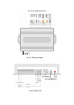
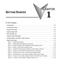
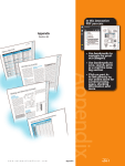
SPECIFICATIONS
CHAPTER
2
In This Chapter...
Available Models . . . . . . . . . . . . . . . . . . . . . . . . . . . . . . . . . . . . . . . . . . . . . . . . . . . .2–2
Model Specifications . . . . . . . . . . . . . . . . . . . . . . . . . . . . . . . . . . . . . . . . . . . . . . . . .2–4
Panel Dimensions (all models) . . . . . . . . . . . . . . . . . . . . . . . . . . . . . . . . . . . . . . . . .2–6
Communications Ports . . . . . . . . . . . . . . . . . . . . . . . . . . . . . . . . . . . . . . . . . . . . . . .2–7
Chemical Compatibility . . . . . . . . . . . . . . . . . . . . . . . . . . . . . . . . . . . . . . . . . . . . . . .2–8
Chapter 2: Specifications
1
2
3
4
5
6
7
8
9
10
11
12
13
14
A
B
C
D
Available Models
The C-more® Micro-Graphic panels continue the next generation of HMI panels brought to
you by AutomationDirect. They have been designed to display and interchange graphical data
from a PLC by merely viewing, using the function keys, or touching the screen (touch screen
model only).
The C-more Micro-Graphic panel is available in four models to suit your application. Refer to
the following table for part numbers, descriptions and general specifications. See Chapter 3:
Accessories for details on the available accessories for the C-more Micro-Graphic panels.
C-more Micro-Graphic Panels
Part Number
Description
3.1-inch C-more Micro-Graphic Touch Panel with green and red LED backlights. Supports 5
selectable backlight colors (Green, Red, Amber, Yellow and Lime). STN LCD monochrome, 128
x 64 dot display. Has 5 user-defined function keys with LED indicators. Power is supplied to the
panel through the serial communication port connection when used with DirectLOGIC PLCs
having an RJ12 communication port. EA-MG-SP1 (power supply with serial option module)
required when connecting to third party PLCs. NEMA 4/4X, IP-65 (when mounted correctly; for
indoor use only).
Touch
Screen
EA1-S3ML
NonTouch
3.1-inch C-more Micro-Graphic Non-Touch Panel with green and red LED backlights. Supports
5 selectable backlight colors (Green, Red, Amber, Yellow and Lime). STN LCD monochrome, 128
x 64 dot display. Has 5 user-defined function keys with LED indicators. Power is supplied to the
panel through the serial communication port connection when used with DirectLOGIC PLCs
having an RJ12 communication port. EA-MG-SP1 (power supply with serial option module)
required when connecting to third party PLCs. NEMA 4/4X, IP-65 (when mounted correctly; for
indoor use only).
EA1-S3ML-N
3.1-inch C-more Micro-Graphic Touch Panel with High Contrast white and red LED backlights.
Supports 5 selectable backlight colors (White, Pink1, Pink2, Pink3 and Red). STN LCD
monochrome, 128 x 64 dot display. Has 5 user-defined function keys with LED indicators. Power
is supplied to the panel through the serial communication port connection when used with
DirectLOGIC PLCs having an RJ12 communication port. EA-MG-SP1 (power supply with serial
option module) required when connecting to third party PLCs. NEMA 4/4X, IP-65 (when
mounted correctly; for indoor use only).
Touch
Screen
EA1-S3MLW*
NonTouch
3.1-inch C-more Micro-Graphic Non-Touch Panel with High Contrast white and red LED
backlights. Supports 5 selectable backlight colors (White, Pink1, Pink2, Pink3 and Red). STN
LCD monochrome, 128 x 64 dot display. Has 5 user-defined function keys with LED indicators.
Power is supplied to the panel through the serial communication port connection when used with
DirectLOGIC PLCs having an RJ12 communication port. EA-MG-SP1 (power supply with serial
option module) required when connecting to third party PLCs. NEMA 4/4X, IP-65 (when
mounted correctly; for indoor use only).
EA1-S3MLW-N*
2–2
*NOTE: C-more Micro-Graphic panels with the letter “W” in the part number designate units with 5 selectable
background colors of White, Pink1, Pink2, Pink3 and Red. Part numbers without the letter “W” are provided
with 5 selectable background colors of Green, Red, Amber, Yellow and Lime.
*NOTE: Software and Firmware Version 1.5 or later is required with models EA1-S3MLW and
EA1-S3MLW-N. Available for free download at www.automationdirect.com..
®
EA1-MG-USER-M Hardware User Manual, 2nd Ed. Rev. C, 06/13
Chapter 2: Specifications
Hardware Version
Product Package Label
Product Label
C-more 3” Micro Graphic panels with hardware version R04 and higher must use firmware version 3.20
or higher.
®
EA1-MG-USER-M Hardware User Manual, 2nd Ed. Rev. C, 06/13
1
2
3
4
5
6
7
8
9
10
11
12
13
14
A
B
C
D
2–3
Chapter 2: Specifications
1
2
3
4
5
6
7
8
9
10
11
12
13
14
A
B
C
D
Model Specifications
The following table on the next two pages provide details to the Specifications of each available
C-more Micro-Graphic model.
Model
Specification
Part Number:
3” STN Micro-Graphic Panel
Touch Screen
3” STN Micro-Graphic Panel
non Touch Screen
EA1-S3ML, EA1-S3MLW
EA1-S3ML-N, EA1-S3MLW-N
128 x 64 dots LCD display, five user defined keypad function buttons,
and five user defined LED's
Description:
Display:
• Type
• Resolution
• Color
• Viewing Area Size
• Active Area Size
• Contrast
• Viewing Angle
3.1" STN monochrome LCD, graphical characters
128 (W) x 64 (H) dots
2 colors (normal / inverse)
2.789” (W) x 1.385” (H) [70.8 mm x 35.2 mm]
2.670” (W) x 1.259” (H) [67.8 mm x 32.0 mm]
Adjusted from the panel’s built-in configuration setup menu
3, 9 o’clock axis –> 45 degrees
6 o’clock axis –> 45 degrees
12 o’clock axis –> 30 degrees
Backlight:
• Type
LED
• Color
5 user defined colors:EA1-S3ML, EA1-S3ML-N - Red, Green, Amber, Lime, and Yellow
EA1-S3MLW, EA1-S3MLW-N - White, Pink1, Pink2, Pink3 and Red
• User Replaceable
Touch Screen:
•Type
• Operation
• Life
Features:
• User Memory
• Number of Screens
• Beep (Internal)
• Keypad Function
Buttons
• Keypad Function
Button LEDs
2–4
• Serial Communications
• Expansion Connection
No
Analog touch panel
N/A
51 gram force [0.5 N] maximum
N/A
Minimum of 1,000,000 cycles
N/A
768 kBytes
Up to 999 – limited by project memory usage
Yes
Five user defined function key push buttons with the ability to label.
Minimum of 500,000 cycles
Each function key button includes a red LED that can be user programmed.
Built-in RJ12 serial communications port (RS-232).
Optional serial communications port (RS-232, RS-485/422) when using the optional
EA-MG-SP1 Serial Port with DC Power Adapter.
Yes – used with optional Keypad Bezels, EA-MG-BZ1 & EA-MG-BZ2, and
EA-MG-P1 DC Power Adapter, and EA-MG-SP1 Serial Port with DC Power Adapter.
Specification table continued at the top of the next page.
®
EA1-MG-USER-M Hardware User Manual, 2nd Ed. Rev. C, 06/13
Chapter 2: Specifications
Model Specifications (cont’d)
Model
Specification
Part Number:
Screen Objects:
• Functional Devices
• Static Shapes
• Displayable Fonts
3” STN Micro-Graphic Panel
Touch Screen
3” STN Micro-Graphic Panel
non Touch Screen
EA1-S3ML, EA1-S3MLW
EA1-S3ML-N, EA1-S3MLW-N
Push Button, Switch, Indicator Button, Indicator Light, Graphic Indicator Light, Numeric
Display, Numeric Entry, Inc/Dec Value, Bar Graph, Bitmap Button, Static Bitmap, Dynamic
Bitmap, Recipe Button, Static Text, Lookup Text, Dynamic Text, Screen Change Push
Button, Screen Selector, Adjust Contrast, Function, Key Configuration Object, Line Graph,
Real Time Graph, Bar Meter
Lines, Rectangles, Circles and Frames
Fixed fonts: 4x6 (only in static text), 6x6, 6x8, 8x16, 8x32, 16x16, 16x32,
32x16, 32x32, and Windows fonts
Electrical:
• Input Voltage Range
5.0 VDC (4.75 – 5.25 VDC)
Supplied through the panel’s RJ12 serial communications port connection when used with
any Direct LOGIC PLCs having a RJ12 communication port. Can also be supplied from an
external 12-24 VDC power source when using the optional EA-MG-P1 DC Power Adapter, or
the optional EA-MG-SP1 Serial Port with DC Power Adapter.
• Input Power
• Power Consumption
• Recommended Fuse
• Max. Inrush Current
• Acceptable External
Power Drop
Environmental:
• Operating Temperature
• Storage Temperature
• Humidity
• Environmental Air
• Vibration
• Shock
• Noise Immunity
• Enclosure
• Agency Approvals
1.05 W @ 5 VDC (210 mA)
Type AGC fast acting glass fuse, 250 mA, 250 VAC, ADC p/n AGC-25
No fuse required when directly connected to a PLC or PC with recommended cable.
1 A for 500 µs
Maximum 1 ms
0 to 50 °C (32 to 122 °F)
–20 to +60 °C (–4 to +140 °F)
5–95% RH, non-condensing
No corrosive gases permitted
IEC60068-2-6 (Test Fc), 5-9 Hz: 3.5 mm amplitude, 9-150 Hz: 1.0G, sweeping, at a rate of
1 octave/min. (±10%), 10 sweep cycles per axis on each of 3 mutually perpendicular axes
IEC60068-2-27 (Test Ea), 15 G peak, 11 ms duration, three shocks in each direction
per axis, on 3 mutually perpendicular axes (total of 18 shocks)
EMA ICS3-304
RFI, (145 MHz, 440 Mhz 10 W @ 10 cm)
Impulse 1000 V @ 1 µs pulse
NEMA 4/4X, IP-65 (When mounted correctly, for indoor use only.)
CE (EN61131-2), UL508, CUL Canadian C22.2 No. 142-M95, UL File E157382,
CSA File 234884
Physical:
• Dimensions
• Enclosure Mounting
Thickness Range
• Mounting Clip Screw
Torque Range
• Depth from bezel rear
with options Module
• Weight
®
4.488” (W) x 3.228” (H) x 1.593” (D) [114.0 mm x 82.0 mm x 40.5 mm]
0.04” – 0.2” [1 – 5 mm]
21 – 28 oz-in [0.15 – 0.2 Nm]
2.295” [58.3 mm]
1
2
3
4
5
6
7
8
9
10
11
12
13
14
A
B
C
D
5.82 oz. (165 g)
EA1-MG-USER-M Hardware User Manual, 2nd Ed. Rev. C, 06/13
2–5
Chapter 2: Specifications
1
2
3
4
5
6
7
8
9
10
11
12
13
14
A
B
C
D
Panel Dimensions (all models)
2–6
4.488
[114.0]
RS232 Serial
Port 1
3.976
[101.0]
Panel Dimensions
MOUNTING CLIP
(2) places
2.835
[72.0]
1.357
[34.5]
GASKET
0.236
[6.0]
1.144
[29.1]
TOP VIEW
Units: inches [mm]
RS232 Serial
Port 1
C-more 3” Micro-Graphic Panel
3.228
[82.0]
3.409
[86.6]
2.716
[69.0]
FRONT VIEW
LEFT VIEW
Enclosure Thickness
ENCLOSURE MOUNTING
THICKNESS RANGE
0.04" – 0.2" [1– 5 mm]
MOUNTING CLIP
(2) places
Mounting Clip Screw Torque
MOUNTING CLIP
SCREW TORQUE RANGE
21-28 oz-in [0.15-0.2 Nm]
NOTE: A minimum clearance of 1.2 inches (30mm) must be maintained around and behind the panel to allow
for proper cooling.
®
EA1-MG-USER-M Hardware User Manual, 2nd Ed. Rev. C, 06/13
Chapter 2: Specifications
Communications Ports
Port 1 (built-in)
C-more
Micro-Graphic
panel
RJ12 serial
communications port 1
Pin
6 5 4 3 2 1
Signal
1
Logic GND
2
not used
3
RXD (232C)
4
TXD (232C)
5
+5 VDC
6
Logic GND
Port 2 (optional)
NOTE: If the DC
power adapter
is installed on
the panel, the
adapter must be
powered and
the panel not
dependent on
+5 VDC from
the PLC’s RJ12
comm port.
Serial Port w/
DC Power Adapter
EA-MG-SP1
Expansion
Connector
PLC 15-pin serial
communications port 2
Signal
8
1
15
9
Pin
Signal
Pin
1
Frame GND
6
LE
Pin
11
Signal
2
TXD (232C)
7
CTS (232C)
12 TXD– (422/485)
3
RXD (232C)
8
RTS (232C)
13 Term. Resistor
4
do not use
9
RXD+ (422/485)
14 do not use
5
Logic GND
10 RXD– (422/485)
15 do not use
TXD+ (422/485)
NOTE: Adapter requires 10.8-26.4 VDC supply.
NOTE: The panel has one built-in RJ12 serial communications port (Port 1 - RS-232) and the option to add
one 15-pin serial communications port (Port 2 - RS-232/422/485) to the panel by installing the EA-MG-SP1
module. Only one of the ports can be used with a connected PLC. The programming software allows the user
to select either Comm. Port1 or Comm. Port2 under the Panel Manager dialog box. When using Port 2 to
communicate with the connected PLC, Port 1 can still be used with the EA-MG-PGM-CBL Software
Programming Cable Assembly to transfer projects between the PC and panel.
®
EA1-MG-USER-M Hardware User Manual, 2nd Ed. Rev. C, 06/13
1
2
3
4
5
6
7
8
9
10
11
12
13
14
A
B
C
D
2–7
Chapter 2: Specifications
1
2
3
4
5
6
7
8
9
10
11
12
13
14
A
B
C
D
Chemical Compatibility
2–8
The C-more Micro-Graphic panels and accessory bezels are made of three materials that may be
exposed to elements outside of the enclosure. The structural hard plastic of the panels and
accessory bezels is ABS plastic. The gasket is silicone rubber. The overlay sheet for all 3" panels,
4" panels and accessory bezels is PET. For EA1-S6ML and EA1-S6MLW panels, the panel
overlay sheet from original manufacture until January 2013 is PC. For EA1-S6ML and EA1S6MLW panels with a manufacture date January 2013 and later, the panel overlay sheet is PET.
For EA1-T6CL panels, the panel overlay sheet from original manufacture until February 2013
is PC. For EA1-T6CL panels with a manufacture date February 2013 and later, the panel
overlay sheet is PET.
®
EA1-MG-USER-M Hardware User Manual, 2nd Ed. Rev. C, 06/13