1
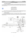
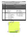
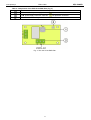
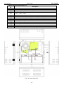
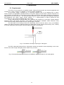
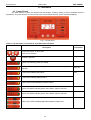
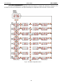
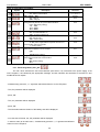
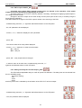
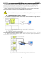
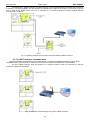
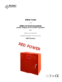
EN54-7A28 v.1.0 EN54 27,6V/7A/2x28Ah power supply for fire alarm systems EN** Edition: 2 from 02.05.2014 Supersedes the edition: 1 from 28.11.2013 LED Version www.pulsar.pl RED POWER EN54-7A28 TABLE OF CONTENTS 1. PSU FEATURES: ......................................................................................................................................... 4 2. PACKAGE CONTENTS. ............................................................................................................................ 5 3. FUNCTIONAL REQUIREMENTS OF THE PSU................................................................................. 6 4. TECHNICAL DESCRIPTION. ................................................................................................................. 7 4.1. GENERAL DESCRIPTION. ...............................................................................................................................................................7 4.2. BLOCK DIAGRAM ..........................................................................................................................................................................7 4.3. DESCRIPTION OF COMPONENTS AND POWER SUPPLY TERMINALS. .............................................................................................8 5. INSTALLATION........................................................................................................................................ 11 5.1. REQUIREMENTS. .........................................................................................................................................................................11 5.2. INSTALLATION PROCEDURE. ......................................................................................................................................................12 6. FUNCTIONS. .............................................................................................................................................. 13 6.1. CONTROL P ANEL. .......................................................................................................................................................................13 6.2. MAIN MENU. ...............................................................................................................................................................................14 6.2.1. Voltage indicator „Uo1”, „Uo2” ...........................................................................................15 6.2.2. Total current of the receivers indicator „Io” .............................................................................................. 15 6.2.3. Resistance of the battery circuit indicator „bre” 6.2.4. Battery temperature indicator „t°C” .........................................................................................15 ..........................................................................................................15 6.2.5. 230V AC mains voltage indicator „UAC” 6.2.6. Failure history “FLh” ..................................................................................................15 . ..................................................................................................................................15 6.2.7. Current failures „FLc” ................................................................................................................................16 6.2.8. List of failure codes and information messages. ..............................................................................................................17 6.3. PSU CONFIGURATION.................................................................................................................................................................19 6.3.1. Performing battery test „tSt” . .......................................................................................................................20 6.3.2. EXTo output ON/OFF„Eto” . .........................................................................................................................21 6.3.3. Setting the delay time for EPS output „EPS” 6.3.4. Acoustic indication ON/OFF „bUZ" 6.3.5. LED Display Dimmer „dIS" . ..............................................................................................21 . ............................................................................................................22 . .......................................................................................................................23 6.3.6. Setting the communication address Adr” applies to cooperation with PowerSecurity. ...................24 6.3.7. Setting the transmission speed „trS” applies to cooperation with PowerSecurity.....................24 6.3.8. Setting the parity of the transmission “trP” applies to cooperation with PowerSecurity................25 6.4. TECHNICAL OUTPUTS. ................................................................................................................................................................26 6.5. INPUT OF COLLECTIVE FAILURE: EXTI. .....................................................................................................................................26 6.6. INDICATION OF THE ENCLOSURE OPENING - TAMPER. ...........................................................................................................27 6.7. INCREASING THE NUMBER OF OUTPUTS WITH OPTIONAL EN54-LB4 OR EN54-LB8 FUSE MODULES. ..................................28 6.8. OVERVOLTAGE PROTECTION OF THE PSU OUTPUT OVP. ........................................................................................................28 6.9. PSU OVERLOAD..........................................................................................................................................................................29 6.10. INDICATION OF EXCEEDING IMAX A CURRENT. .......................................................................................................................29 6.11. SHORT-CIRCUIT OF THE PSU OUTPUT. ....................................................................................................................................29 2 www.pulsar.pl EN54-7A28 RED POWER 7. RESERVE POWER SUPPLY CIRCUIT. .............................................................................................. 30 7.1. BATTERY DETECTION. ................................................................................................................................................................30 7.2. PROTECTION AGAINST SHORT-CIRCUIT OF THE BATTERY TERMINALS. ....................................................................................30 7.3. PROTECTION AGAINST REVERSE BATTERY CONNECTION. ........................................................................................................30 7.4. DEEP DISCHARGE BATTERY PROTECTION UVP.........................................................................................................................30 7.5. BATTERY TEST. ...........................................................................................................................................................................30 7.6. MEASUREMENT OF THE RESISTANCE OF THE BATTERY CIRCUIT. .............................................................................................31 7.7. BATTERY TEMPERATURE MEASUREMENT. ................................................................................................................................31 7.8. STANDBY TIME. ..........................................................................................................................................................................31 8. REMOTE MONITORING (OPTIONS: WI-FI, ETHERNET, RS485, USB).................................. 32 8.1. COMMUNICATION VIA THE USB-TTL INTERFACE....................................................................................................................32 8.2. ETHERNET NETWORK COMMUNICATION................................................................................................................................32 8.3. THE WI-FI WIRELESS COMMUNICATION. ...................................................................................................................................33 8.4. RS485 NETWORK COMMUNICATION. .........................................................................................................................................34 8.5. „POWERSECURITY” PROGRAM...................................................................................................................................................35 9. TECHNICAL PARAMETERS. ............................................................................................................... 36 Table 12. Electrical parameters. .................................................................................................................................................36 Table 13. Mechanical parameters. ..............................................................................................................................................37 Table 14. Safety of use..................................................................................................................................................................37 Table 15. Recommended types and sections of installation cables. ..........................................................................................37 10. TECHNICAL INSPECTIONS AND MAINTENANCE. ................................................................... 38 3 www.pulsar.pl EN54-7A28 RED POWER 1. PSU features: In accordance with standards: EN 54-4, EN12101-10 27,6V DC/ 7A uninterruptible power supply battery housing for two 28Ah/12V batteries independently protected outputs AUX1 and AUX2 high efficiency 82% low level of voltage ripple microprocessor-based automation system intelligent PSU overload protection measurement of the resistance of the battery circuit automatic temperature-compensated charging battery test two-stage battery charging process accelerated battery charging monitoring of the continuity of the battery circuit monitoring of the battery voltage monitoring of the battery fuse monitoring of charging and maintenance of the batteries deep discharge battery protection (UVP) battery overcharge protection battery output protection against short-circuit and reverse connection monitoring of the load current output voltage control fuse monitoring of AUX1and AUX2 outputs 230V AC mains supply voltage measurement „SERIAL” communication port with implemented MODBUS RTU protocol free program "PowerSecurity" to monitor the performance of the PSU remote monitoring (options: WiFi, Ethernet, RS485, USB) remote battery test (additional modules required) cooperation with optional EN54-LB4 or EN54-LB8 fuse modules optical indication of PSU overload OVL acoustic indication of failure adjustable delay for 230V AC power loss indication output of collective failure ALARM input of collective failure EXTi controlled relay output EXTo technical inputs/outputs with galvanic isolation EPS technical output indicating 230V AC power loss PSU technical output indicating PSU failure APS technical output indicating battery failure internal memory of PSU operating status optical indication – LED panel output current readings output voltage readings: AUX1, AUX2 resistance of the battery circuit 230V AC mains voltage readings failure codes with history protections: SCP short-circuit protection OLP overload protection OHP overheat protection OVP overvoltage protection Surge protection Antisabotage protection - Tamper closing the enclosure - lock convection cooling warranty - 5 years from the production date 4 www.pulsar.pl EN54-7A28 2. Package contents. Power Supply Unit User manual CD Red mounting spacers – 4 pieces Red, metal mounting brackets for hanging the power supply – 4 pieces M8x16 mounting screws – 4 pieces PG9 cable glands – 4 pieces PG11 cable glands – 4 pieces Battery serial connection cable Keys to lock the power supply– 2 pieces Cable tie 190x4,8 – 12 pieces 5 RED POWER www.pulsar.pl RED POWER EN54-7A28 3. Functional requirements of the PSU. The buffer power supply for fire alarm systems has been designed in accordance with the following standards: - EN 54-4:2001 and / A2:2007 Fire detection and fire alarm systems. - EN 12101-10:2007 Smoke and heat control systems. Functional requirements External Power Supply failure indication Two independent power supply outputs protected against shortcircuit Temperature-compensated battery charging Measurement of the resistance of the battery circuit Low battery indication Deep discharge battery protection Protection against short-circuit of the battery terminals Battery fuse failure indication Charging circuit failure indication Low output voltage indication High output voltage indication Indication of power supply failure Overvoltage protection Short-circuit protection Overload protection Output of collective failure ALARM EPS technical output APS technical output PSU technical output Input of an external failure indication EXTi Controlled relay output EXTo Remote battery test 230V AC mains supply voltage measurement Optical indication – LED display Tamper indicating enclosure opening 6 Requirements according to standards YES YES YES YES YES YES YES YES YES YES YES YES YES YES YES YES YES YES - PSU EN54-7A28 YES YES YES YES YES YES YES YES YES YES YES YES YES YES YES YES YES YES YES YES YES YES YES YES YES www.pulsar.pl EN54-7A28 RED POWER 4. Technical description. 4.1. General description. The buffer power supply has been designed for an uninterrupted supply of fire alarm systems, smoke and heat control systems, fire protection equipment and fire automatics requiring stabilized voltage of 24V DC (± 15%). The PSU is fitted with two independently protected outputs AUX1 and AUX2, which supply voltage of 27.6 V DC with a total output current: Continuous operation Output current Imax a=5,5A Instantaneous operation Output current Imax b=7A In case of power loss, the PSU switches to battery power, providing uninterruptible power supply. The PSU is enclosed in a metal casing (RAL 3001 - red) with battery housing for two 28Ah/12V batteries. The PSU works with maintenance-free lead acid batteries made with AGM technology or gel technology. 4.2. Block diagram The PSU has been manufactured based on a high-efficiency system of DC/DC converter. Applied microprocessor circuit is responsible for the full diagnostics of the PSU parameters and batteries. The figure below shows a flowchart of the power supply, along with selected functional blocks which are essential for the proper functioning of the unit. Fig. 1. PSU block diagram. 7 www.pulsar.pl RED POWER EN54-7A28 4.3. Description of components and power supply terminals. Table 1. Components of the Power supply PCB (Printed Circuit Board) (Fig. 2). Component No. [1] [2] [3] [4] [5] [6] [7] [8] [9] [10] [11] [12] [13] Description PANEL – optical indication connector BUZZER – acoustic indication VEXT jumper – polarization of the EXTi circuit FBAT – fuse in the battery circuit, F10A / 250V FAUX1 – fuse in the AUX1 output circuit, F8A / 250V FAUX2 – fuse in the AUX2 output circuit, F8A / 250V SERIAL – communication port Z2 jumper - temporary lock of the battery test OVP – overvoltage protection optical indication LEDs – optical indication: (see section 6.3.4) (see section 6.5) (see section 7.5) (see section 6.8) AC – AC power AUX1 – AUX1 output voltage AUX2 – AUX2 output voltage OVL – PSU overload APS – battery failure Terminals: PSU ALARM EXTi EXTo LB ~AC~ – AC power input EPS FLT – technical output of AC power failure indication open = AC power failure closed = AC power - O.K. PSU FLT – technical output of PSU failure indication open = failure closed = PSU operation - O.K. APS FLT – technical output of battery failure open = battery failure closed = battery status - O.K. ALARM – technical output of collective failure open = failure closed = O.K. TAMPER – antisabotage protection microswitch connector Connector– for connecting the EMC filter EXTo EXTi +BAT+AUX1- – controlled relay output – input of collective failure – terminals for connecting the battery – AUX1 power output (+AUX1= +U, -AUX=GND) +AUX2- – AUX2 power output (+AUX2= +U, -AUX=GND) Fig. 2. The view of the PSU’s PCB. 8 – PSU failure – collective failure – EXTi input status – EXTo relay output status – battery charging (see section 6.6) www.pulsar.pl RED POWER EN54-7A28 Table 2. Components of the PCB of the EMC filter (Fig. 3). Element nr Opis FMAINS fuse in the power supply circuit 230V, T6,3A / 250V L-N power supply connector 230V AC, PE protective connector Connector– for connecting the PSU. Fig. 3. The view of the EMC filter. 9 www.pulsar.pl EN54-7A28 Table 3. Elements of the PSU (Fig. 4). Component Description No. [1] Isolation transformer [2] Printed Circuit Board (see Table 1, Fig. 2) [3] Battery temperature sensor. Space to install an additional module: [4] “INTR”, “INTE”, “INTW” [5] Place to install the EN54-LB4 or EN54-LB8 fuse module [6] TAMPER; microswitch (contacts) of antisabotage protection (NC) [7] EMC filter module (see Table 2, Fig. 3) [8] 2x28Ah batteries [9] Embossing for cable gland [10] Embossing for cable gland (WiFi antenna or cable communication interface) [11] Embossings for concealed wires [12] Lock [13] Battery connectors; positive: +BAT = red, negative: - BAT = black Fig.4. The view of the PSU. 10 RED POWER www.pulsar.pl EN54-7A28 RED POWER 5. Installation. 5.1. Requirements. The PSU is to be mounted by a qualified installer, holding relevant permits and licenses (applicable and required for a given country) for 230V/AC in and low-voltage installations. As the power supply is designed for a continuous operation and is not equipped with a powerswitch, therefore, an appropriate overload protection in the power supply circuit should be provided. Moreover, the user should be informed how to disconnect the power supply unit from the mains supply (usually by assigning an appropriate fuse in the fuse box). The electrical system shall be made in accordance with applicable standards and regulations. The power supply should operate in a vertical position in order to provide free and convectional air flow through ventilating holes of the casing. As the PSU performs a periodic battery test, measuring the resistance of connections, special attention should be paid to the proper connection of the cables to the batteries. Installation cables should be firmly connected to the battery side terminals and to the power supply connector. The side walls of the housing include the embossings, which should be used to carry out installation cables. Use a blunt instrument to make an opening for cable gland from the outside of the housing. Then, carefully mount the cable gland, protecting the PSU from water penetration, in the opening. Fig. 5. The method of forming an opening for cable gland. The PSU is fitted with PG9 and PG11 cable glands. Gland size should be chosen depending on the crosssection of the cable. Single cable gland can be used for only one wire. Fig. 6. Recommended types and sections of installation cables PG9 and PG11 for cable glands. 11 www.pulsar.pl RED POWER EN54-7A28 5.2. Installation procedure. CAUTION! Before installation, cut off the voltage in the 230V power-supply circuit. To switch power off, use an external switch, in which the distance between the contacts of all poles in the disconnection state is not less than 3mm 1. Mount the PSU in a selected location with use of special metal expansion bolts. Do not use PVC dowels. 2. Connect the power cables (230V AC) to the L-N terminals of the PSU. Connect the ground wire to the terminal marked with grounding symbol: PE. Use a three-core cable (with a yellow and green PE protection wire) to make the connection. The shock protection circuit shall be done with a particular care: the yellow and green wire coat of the power cable should be connected to the terminal marked with the PE symbol on the PSU enclosure. Operation of the PSU without the properly made and fully operational shock protection circuit is UNACCEPTABLE! It can cause damage to the equipment or an electric shock. 3. Connect the receivers’ cables to the AUX1 and AUX2 output terminals on the PSU board. 4. If needed, connect the cables from the devices to the technical inputs and outputs: - ALARM; technical output of collective failure of the PSU - EPS FLT; technical output of AC power loss indication - PSU FLT; technical output of PSU failure. - APS FLT; technical output of the battery failure. - EXTi; input of collective failure 5. Install the batteries in a designated area of the enclosure (see Fig. 4). Connect the batteries with the PSU paying special attention to the correct polarity. Batteries must be connected in series using the special cable (included). Attach the temperature sensor to any of the batteries with mounting tape (included). 6. Switch on the 230V AC supply. The corresponding LEDs on the power supply PCB should be ON: green AC and green AUX1 and AUX2. Yellow LB LED should light up while charging. 7. Check the current consumption of the receivers, taking into account the battery charging current, so as not to exceed the total current efficiency of the PSU (see section 4.1). 8. Once the tests are completed, close the enclosure. Table 4. Operation parameters. Environmental class PN-EN 12101-10:2007 Operating temperature Storing temperature Relative humidity Sinusoidal vibrations during operation: 10 ÷ 50Hz 50 ÷ 150Hz Surges during operation Direct insolation Vibrations and surges during transport 2 -5ºC...+75ºC -25ºC...+60ºC 20%...90%, no condensation 0,1g 0,5g 0,5J unacceptable According to the PN-83/T-42106 standard Table 5. Factory settings of the PSU. Delay time for EPS technical output 10s indicating AC power loss Acoustic indication ON LED display dimmer OFF EXTo output OFF Communication address 1 Transmission 115.2k 8E1 section 6.3.3 section 6.3.4 section 6.3.5 section 6.3.2 section 6.3.6 section 6.3.7 and 6.3.8 12 www.pulsar.pl EN54-7A28 RED POWER 6. Functions. 6.1. Control Panel. The PSU features a panel with buttons and LED display, enabling reading of all the available electrical parameters. The panel buttons are used to select and confirm the parameters, which should be displayed. Fig. 7. Control panel. Table 6. The description of the buttons and LEDs of the LED panel. Description Additional information - moves the pointer on the screen - next screen selection - selection approval - green LED indicating 230V AC voltage - yellow LED indicating exceeding the Imax a current or power supply overload section 6.9, 6.10 - yellow LED indicating PSU failure section 6.2.3 - yellow LED indicating battery failure - yellow LED ALARM indicating collective failure - green LED AUX1 indicating power at the AUX 1 output of the PSU - green LED AUX2 indicating power at the AUX 2 output of the PSU - three green LEDs indicating approximate battery charge level 13 www.pulsar.pl RED POWER EN54-7A28 6.2. Main menu. The PSU is equipped with a menu, which allows to preview the current electrical parameters. Diagram explaining the menu structure is presented below Fig. 8. Menu of the display. Table 7. The description of display symbols. Symbol Description AUX1 output voltage [V] Additional information Factory setting: 27,6V @ 20°C AUX2 output voltage [V] Factory setting: 27,6V @ 20°C Total current of the receivers [A] Io = I AUX1 + IAUX2 Resistance of the battery circuit [Ω] Section 7.6 Battery temperature [°C] Section 7.7 Mains supply voltage [V] Failure history 230V AC mains supply voltage indication Section 6.2.6 Current failures Section 6.2.7 14 www.pulsar.pl EN54-7A28 RED POWER 6.2.1. Voltage indicator „Uo1”, „Uo2” Voltage indicator displays the measured output voltage at the AUX1 and AUX2 outputs. If the voltage drops below 26V or exceeds 29.2V, the PSU will indicate a failure. The resolution of voltage measurement is 0.1V and should be treated with caution. If a greater accuracy is required, use a multimeter. 6.2.2. Total current of the receivers indicator „Io” Total output current indicator displays the measured output current drawn from the AUX1 and AUX2 outputs. If the value of total current is exceeded, the power supply unit will indicate a failure. Io = IAUX1 + IAUX2 The resolution of current measurement is 0.1A and should be treated with caution. If a greater accuracy is required, use a multimeter. 6.2.3. Resistance of the battery circuit indicator „bre” Resistance of the battery circuit indicator displays the measured resistance of the battery circuit of the PSU. The resistance value is affected by: - The quality of the batteries - The quality of the battery cables and connections - The quality of the FBAT fuse If the resistance drops below 300 mΩ, the power supply unit will indicate a failure. The measurement result is displayed with a resolution of 0.01 ohm. 6.2.4. Battery temperature indicator „t°C” Battery voltage indicator displays the measured temperature of the batteries. The temperature is used by the automatic control system for compensation of the battery charging voltage. The measurement result is displayed with a resolution of 1°C. 6.2.5. 230V AC mains voltage indicator „UAC” 230V AC mains voltage indicator displays the measured mains voltage at the 230V AC mains terminals. If the voltage drops below 195V AC or exceeds 254V AC, the power supply unit will indicate a failure. The resolution of current measurement is 1V and should be treated with caution. If a greater accuracy is required, use a multimeter. 6.2.6. Failure history “FLh” . The PSU remembers 30 last failures in non-volatile memory, which can be reviewed later. In order to review the failures, use the "<" or ">" button to set the FLh parameter and confirm by pressing "OK". The display will show the number of failure in the memory and its code. Pressing the "OK" button again will display next failure in the memory. The memory of the new power supply remembers the events that are the result of the efficiency tests carried out at the production stage. - press „<” or „>” button to set the „FLh” parameter on the display 15 www.pulsar.pl EN54-7A28 RED POWER - press „OK” button - number 1, indicating the number of failure in the memory (the highest priority), will be displayed. Then, after one second, failure code will be displayed automatically - press „OK” button - the number 2, denoting the next number of failure in the memory, will be displayed. Then, after one second, the next failure code will be displayed automatically - if the memory has more failures, pressing the "OK" button will result in displaying subsequent codes - The „- - -„ parameter on the display marks the end of the list of failures 6.2.7. Current failures „FLc” . In case of abnormal electrical parameters, the power supply provides optical and acoustic indication of the failure via corresponding LED and a beeper (if not disabled). The PSU can simultaneously indicate several failures. Thanks to this solution, codes of all failures and their priority can be previewed in the FLc menu. In the FLc menu, each press of the "OK" button on the panel displays the next error code that caused the failure. If there are multiple failures at the same time, pressing the "OK" button will display the next code. The display order of failures is arranged by priority of importance. The first failures in the display order are of the highest priority. Section 6.2.8. summarizes all the failure codes that may occur during the power supply operation. The individual codes are accompanied by appropriate optical indication on the panel, acoustic indication and activation of the dedicated technical output. - press „<” or „>” button to set the „FLc” parameter on the display - press „OK” button - the number 1, indicating the number of failure in the memory (the highest priority), will be displayed. Then, after one second, failure code will be displayed automatically 16 www.pulsar.pl EN54-7A28 RED POWER - press „OK” button - the number 2, denoting the next number of failure in the memory, will be displayed. Then, after one second, the next failure code will be displayed automatically - if the memory has more failures, pressing the "OK" button will result in displaying Subsequent codes - The „- - -„ parameter on the display marks the end of the list of failures 6.2.8. List of failure codes and information messages. The PSU indicates the operation status with the appropriate code. The codes are divided into two groups,marked with the initial letters "F" or "I”. The codes beginning with the letter "F" indicate a failure. The codes that begin with the letter "I" indicate the correct operation of the PSU or repaired fault, involving, for example, fuse replacement: "I03 - BAT fuse replaced”. Table 8. List of PSU failure codes. Technical Failure Information output code activation F01 No AC power! EPS FLT F02 AUX1 fuse! AUX2 fuse! PSU FLT, ALARM F03 BAT fuse! APS FLT, ALARM F04 F05 F06 F08 F09 F10 F11 F12 F14 F15 Additional information - No AC mains supply FMAIN fuse failure Blown FAUX1 fuse Blown FAUX2 fuse Blown FBAT fuse Short circuit in the battery circuit Short circuit in the AUX output circuit Overloaded output! Undercharged battery! High AUX1 voltage! High AUX2 voltage! PSU FLT, ALARM APS FLT, ALARM PSU FLT, ALARM - Output voltage over 29.2V Faulty battery charging circuit! PSU FLT, ALARM - The output voltage of the PSU set too low , below 26V - Battery charging circuit failure PSU FLT, ALARM - Output voltage below 26V APS FLT, ALARM APS FLT, ALARM - The battery voltage has dropped below 23V (during battery-assisted operation - the battery voltage has dropped below 20V (during battery-assisted operation) Low AUX1 voltage! Low AUX2 voltage! Low battery voltage! Low battery voltage – off! EXT external output! Temperature sensor failure! High battery ALARM PSU FLT, ALARM PSU FLT, Additional information - PSU overload - Spent batteries - Undercharged batteries - Activation of the input of collective failure: EXTi - Faulty temperature sensor - Temperature sensor disconnected - Too high ambient temperature of the PSU. 17 Section 6.9 Section 7 Section 7.4 Section 6.5 Section 7.7 Section 7.7 www.pulsar.pl temperature F16 No battery! F17 Faulty battery! F18 F19 F20 F21 F50F54 F60 High resistance of the. Battery circuit! High AC voltage! Low AC voltage! Enclosure opening! Internal damage of the PSU. No communication F61F64 LCD damage F65 Access unlocked EN54-7A28 ALARM APS FLT, ALARM APS FLT, ALARM APS FLT, ALARM PSU FLT, ALARM PSU FLT, ALARM PSU FLT, ALARM PSU FLT, ALARM PSU FLT, ALARM PSU FLT, ALARM RED POWER - Overloaded batteries. - Faulty batteries. - Disconnected batteries - Deeply discharged batteries , voltage below 20V - Spent batteries - Loose cables connecting the batteries - Mains supply over 254V AC - Mains supply below 195V AC Section 7.1 Section 7 Section 7.6 Section 6.2.5. Section 6.2.5. Section 6.6 - service codes - no communication with LCD panel - service codes - passwords unlocked Table 9. List of PSU message codes. Message Description code I00 Running the PSU I01 AC power restored AUX1 fuse replaced I02 AUX2 fuse replaced I03 BAT fuse replaced I04 Battery connected I05 Battery OK I06 Correct battery temperature I07 Correct AC voltage I08 EXTo output on I09 EXTo output off I10 Battery test – START I11 PSU’s lid closed I12 The Imax_a current exceeded I13 The current has dropped below Imax_a 18 www.pulsar.pl EN54-7A28 RED POWER 6.3. PSU configuration. The PSU is equipped with a configuration menu that allows to configure the settings by changing or the activation of some of its parameters. The figure illustrating the configuration menu structure is shown below. Fig. 9. The PSU configuration menu. 19 www.pulsar.pl RED POWER EN54-7A28 Table 10. Description of symbols. Symbol Description Battery test – „tSt” On – battery test activation EXTo output – „Eto” On – relay on OFF – relay off EPS output delay – „EPS” Setting the delay time for AC power failure indication: 0.10 - 10s (factory setting) 1.0 - 1min 10.0 - 10min 30.0 - 30min Acoustic indication – „bUZ” On – acoustic indication on OFF – acoustic indication off LED display dimmer On – dimmer ON OFF – dimmer OFF Communication address – „Adr” 1÷ 247 power supply address required at the time of communication with the computer 1 – factory setting Transmission – „trS” Determines the speed of communication 9.6k : 115.2k (factory setting) Parity of the transmission – „trP” Determines the method of communication 8N2 8E1 (factory setting) 8O1 6.3.1. Performing battery test „tSt” Additional information Sections 6.3.1 and 7.5 Section 6.3.2 Section 6.3.3 Section 6.3.4 Section 6.3.5 Section 6.3.6 Section 6.3.7 Section 6.3.8 . The "tSt" menu activates the test of the batteries (see section 7.5) connected to the power supply. If the test is negative, it is indicated by the appropriate message, acoustic indication and activation of the APS FLT and ALARM technical outputs. - simultaneously press the „<,>” rightmost and leftmost buttons on the LED panel - The „tSt” parameter will be displayed - press „OK” - The „On” parameter will be displayed - press „OK” - The information about activation of the battery test will be displayed - once the test is finished, the „tSt” parameter will be displayed - in order to return to the main menu, simultaneously press the „<,>” rightmost and leftmost buttons on the LED panel 20 www.pulsar.pl RED POWER EN54-7A28 6.3.2. EXTo output ON/OFF„Eto” . Controlled relay output EXTo (external output) does not depend on the operation of the power supply unit and can be switched independently of its work. The EXTo output can be used for switching between controlling, resetting and supplying inputs/outputs in low-voltage electrical circuits. Changes in the EXTo output can be made locally from the panel (see section 6.3.2) or remotely using the PowerSecurity application. Information about the changes in the EXTo output is written in the event log of the PSU. - simultaneously press the „<,>” rightmost and leftmost buttons on the LED panel - the „tSt” parameter will be displayed - use the „<” or „>” buttons to display the „Eto” parameter - press „OK” - The current status of the relay will be displayed - use the „<” or „>” buttons to in order to set the status On – relay on OFF – relay off - press „OK” – relay output status is changed - in order to return to the main menu, simultaneously press the „<,>” rightmost and leftmost buttons on the LED panel 6.3.3. Setting the delay time for EPS output „EPS” . The PSU features adjustable delay for 230V AC power loss indication. The delay time can be selected from the four available ranges: - 10s (factory setting) - 1min - 10min - 30min 230V AC power loss is indicated by the activation of the “EPS FLT” technical output. - simultaneously press the „<,>” rightmost and leftmost buttons on the LED panel - The „tSt” parameter will be displayed 21 www.pulsar.pl RED POWER EN54-7A28 - use the „<” or „>” buttons to display the „EPS” parameter - press „OK” - The current status will be displayed - use the „<” or „>” buttons in order to set the delay time 0.10 - 10s (factory setting) 1.0 - 1min 10.0 - 10min 30.0 - 30min - confirm by pressing "OK" - in order to return to the main menu, simultaneously press the „<,>” rightmost and leftmost buttons 6.3.4. Acoustic indication ON/OFF „bUZ" . Emergency situations that may arise during the operation of the PSU are indicated acoustically. The frequency and number of signals depend on the type of event. Table 11. Acoustic indication. No. Description 1 2 3 4 5 1 signal every 10s, battery mode 1 signal every 10s, mains operation 2 signals every 10s, battery mode Fast signals, battery mode Constant indication Event 230V AC power failure Battery failure, undercharged batteries Low battery level The PSU will be disconnected because of the battery discharge PSU failure [see section 6.2.8] - simultaneously press the „<,>” rightmost and leftmost buttons on the LED panel - The „tSt” parameter will be displayed - use the „<” or „>” buttons to display the „bU2” parameter - press „OK” - The current status will be displayed 22 www.pulsar.pl EN54-7A28 RED POWER - use the „<” or „>” buttons in order to set the status On – acoustic indication on OFF – acoustic indication off - confirm by pressing "OK" - in order to return to the main menu, simultaneously press the „<,>” rightmost and leftmost buttons 6.3.5. LED Display Dimmer „dIS" . LED display dimmer allows to dim the display if no buttons are pressed within 5 minutes.If the display is in the blackout mode, pressing any button will "reactivate" the display. - simultaneously press the „<,>” rightmost and leftmost buttons on the LED panel - the „tSt” parameter will be displayed - use the „<” or „>” buttons to display the „dIS” parameter - press „OK” - The current status will be displayed - use the „<” or „>” buttons in order to set the status On – dimmer on OFF – dimmer off - confirm by pressing "OK" - in order to return to the main menu, simultaneously press the „<,>” rightmost and leftmost buttons 23 www.pulsar.pl RED POWER EN54-7A28 6.3.6. Setting the communication address Adr” PowerSecurity. applies to cooperation with All power supplies are factory-set to address 1. All the parameters responsible for communication between the PSU and the computer, namely the address, parity and speed should have the same settings for both the PSU and the PowerSecurity program. Communication address allows to identify power supply units in the same communication network. - simultaneously press the „<,>” rightmost and leftmost buttons - The „tSt” parameter will be displayed - use the „<” or „>” buttons to display the „Adr” parameter - press „OK” - The current address of the PSU will be displayed - use the „<” or „>” buttons in order to set the address 1÷ 247 – address of the PSU during the communication with the computer - confirm by pressing „OK” - in order to return to the main menu, simultaneously press the „<,>” rightmost and leftmost buttons 6.3.7. Setting the transmission speed „trS” PowerSecurity. applies to cooperation with All the parameters responsible for communication between the PSU and the computer, namely the address, parity and speed should have the same settings for both the PSU and the PowerSecurity program. The PSU has preset transmission parameters of 115200 baud 8E1; if these values were changed, they should be restored to original settings. - simultaneously press the „<,>” rightmost and leftmost buttons - The „tSt” parameter will be displayed 24 www.pulsar.pl RED POWER EN54-7A28 - use the „<” or „>” buttons to display the „trS” parameter - press „OK” - The information about the transmission speed will be displayed - use the „<” or „>” buttons in order to set the required transmission speed, - 9.6k : - 115.2k (factory setting) - confirm by pressing „OK” - in order to return to the main menu, simultaneously press the „<,>” rightmost and leftmost buttons 6.3.8. Setting the parity of the transmission “trP” PowerSecurity applies to cooperation with All the parameters responsible for communication between the PSU and the computer, namely the address, parity and speed should have the same settings for both the PSU and the PowerSecurity program. The PSU has preset transmission parameters of 115200 baud 8E1; if these values were changed, they should be restored to original settings. - simultaneously press the „<,>” rightmost and leftmost buttons - The „tSt” parameter will be displayed - use the „<” or „>” buttons to display the „trP” parameter - press „OK” - The information about the parity of the transmission will be displayed on the panel - use the „<” or „>” buttons in order to set the required communication mode, - 8N2 - 8E1 (factory setting) - 8O1 - confirm by pressing „OK” - in order to return to the main menu, simultaneously press the „<,>” rightmost and leftmost buttons 25 www.pulsar.pl EN54-7A28 RED POWER 6.4. Technical outputs. The PSU is equipped with galvanically isolated indication outputs changing status after a specified event: EPS FLT – output indicating AC power loss. The output indicates 230V AC power loss. Under normal status – with the 230V AC supply on, the output is closed. In case of power failure, the PSU will switch the output into the open position after a time lag determined in the „EPS” configuration menu (see section 6.3.3, Table 10). APS FLT – output indicating battery failure. The output indicates a failure in the battery circuit. Under normal status (during correct operation) the output is closed. In case of failure, the PSU will switch the output into the open position. Failure can be triggered by the following events: - faulty batteries - undercharged batteries - disconnected batteries - high resistance of the battery circuit - battery voltage below 23V during battery-assisted operation - battery fuse failure - no continuity in the battery circuit PSU FLT – output indicating PSU failure. The output indicates the PSU failure. Under normal status (during correct operation) the output is closed. In case of PSU failure, it will switch into the open position. Failure can be triggered by the following events: - UAUX1, AUX2 output voltage below 26V - UAUX1, AUX2 output voltage over 29,2V - battery charging circuit failure - blown FAUX1 or FAUX2 fuse - exceeding the rated current of the PSU - activation of overvoltage protection OVP - mains supply voltage over 254V AC - mains supply voltage below 195V AC - too high ambient temperature of the batteries - temperature sensor failure - enclosure opening - TAMPER - internal damage of the PSU The technical outputs have been made with galvanic isolation between the PSU’s systems and the attached devices. Fig. 10. Electrical diagram of technical outputs. 6.5. Input of collective failure: EXTi. The EXT IN (external input) technical input indicating collective failure is intended for additional, external devices that generate the failure signal. The voltage appearing at the EXT IN input will trigger PSU failure, storing the information about the event in the internal memory and sending the signal about the failure to the ALARM output. The EXT IN technical input has been made with galvanic isolation between the PSU’s systems and the attached devices. Fig. 11. Electrical diagram of the EXT IN input. 26 www.pulsar.pl EN54-7A28 RED POWER The connection of external devices to the EXT IN input is shown in the electrical diagram below. OC outputs (open collector) or relay outputs can be used as the source of the signal. Fig. 12. Examples of connections. In the option with external switch, the V EXT jumper, which polarises the EXT IN input circuit and is required in such configuration, must be on. The EXTi input has been adjusted to work with fuse modules generating a failure signal in case of a fuse fault in any of output sections (see section 6.7). To guarantee a correct cooperation between the fuse module and the EXTi input, the connections shall be made as presented in the diagram below and the V EXT jumper must be on. Fig. 13. Example of a connection with the fuse module EN54-LB8. 6.6. Indication of the enclosure opening - TAMPER. The PSU is fitted with the microswitch tamper indicating enclosure opening. The tamper cable is not connected to the terminal in the factory settings. In order to activate tamper, remove the jumper from tamper terminal (Fig. 2 [12]) and plug in the tamper cable. Each opening the enclosure will generate a failure signal at the PSU FLT and ALARM technical outputs and will save the event in the internal memory of the PSU. 27 www.pulsar.pl EN54-7A28 RED POWER 6.7. Increasing the number of outputs with optional EN54-LB4 or EN54-LB8 fuse modules. The PSU has two independently protected outputs for connecting the AUX1 and AUX2 receivers. If the power supply unit is connected with more receivers, then it is recommended to secure each of them with independent fuse. This solution will protect the power supply system, while the damage to only one receiver (shortcircuit on the line) could cause damage to other receivers connected to the same output. The solution is provided by the optional fuse module EN54-LB4, 4-channel or EN54-LB8, 8-channel, while its mounting location is provided within the housing (see Fig. 4). The figure below shows the connection between the power supply, fuse module and receivers. Fig.14. The connection of fuse module When installing the fuse module in the PSU, power supply current consumption, used for the calculation of standby time (see section 7.8), should be taken into account. Depending on the version, fuse module allows to connect 4 or 8 receivers to the PSU. Output state is indicated by green LEDs. Blown fuse is indicated as follows: - corresponding LED turns off: L1 for AUX1 etc. - red LED on - PSU technical output on (Hi-Z state) - switching PSU relay output into voltage free status (contacts as shown in the Fig.14). In addition, blown fuse signal is transmitted to the input of collective failure EXTi (ALARM) and saved in the internal memory of PSU. The PSU’s relay output can also be used for remote control, including external optical indication. 6.8. Overvoltage protection of the PSU output OVP. In case of voltage exceeding 30,5V±0.5V at the switching regulator’s output, the system cuts off the power at the outputs to protect the battery and the receivers from damage. The outputs will be batterypowered. The activation of the protection system is indicated by the OVP yellow LED on the PCB board, and the PSU FLT and ALARM outputs. 28 www.pulsar.pl EN54-7A28 RED POWER 6.9. PSU overload. The PSU is fitted with the LED OVL (overload) on the PCB and indicator on the LED panel, informing about output overload. If the nominal current of the PSU is exceeded, the led turns on and the microprocessor starts a specially implemented procedure. Depending on time and overload level, microprocessor may disconnect the AUX1 and AUX2 outputs and switch into the battery-assisted operation. Restart will occur after 1 minute. PSU overload is indicated by the PSU FLT and ALARM technical outputs. 6.10. Indication of exceeding Imax a current. Exceeding the "Imax a" output current during the power supply operation is indicated by the microprocessor using the LED OVL light (overload) on the PCB and LED indicator light on the LED panel of the power supply after 30 seconds. Information about exceeding the „Imax a” current is stored in the history of events. Battery charge current is limited in order to protect the power supply against overload. 6.11. Short-circuit of the PSU output. In case of short-circuit of the AUX1 or AUX2 output, one of the fuses - FAUX1 or FAUX2 – becomes permanently blown. The restoration of the voltage at the output requires the replacement of the fuse 29 www.pulsar.pl EN54-7A28 RED POWER 7. Reserve power supply circuit. The PSU is fitted with intelligent circuits: battery charging circuit with the function of the accelerated charging and battery control, which main task is to monitor the condition of the batteries and the connections in the circuit. If the controller detects a power failure in the battery circuit, appropriate indication and activation of the APS FLT and ALARM technical outputs takes place. 7.1. Battery detection. The control unit of the PSU checks the voltage at the battery terminals and, depending on the measured values, determines the appropriate reaction: UBAT below 4V - batteries not connected to the PSU circuits UBAT = 4 to 20V - faulty batteries UBAT over 20V - batteries connected to the PSU circuits 7.2. Protection against short-circuit of the battery terminals. The PSU is fitted with the circuit protecting against short-circuit of the battery terminals. In case of short circuit, control circuit immediately disconnects the batteries from the rest of the power supply circuit, so the loss of output voltage on power supply outputs is not observed. Automatic reconnection of the batteries to the PSU's circuits is only possible after the removal of the short-circuit and correct connection of the circuits. 7.3. Protection against reverse battery connection. The PSU is protected against reverse connection of the battery terminals. In case of incorrect connection, the FBAT fuse in the battery circuit becomes blown. The return to normal operation is possible only after replacing the fuse and correct connection of the batteries. 7.4. Deep discharge battery protection UVP. The PSU is fitted with the disconnection system and the battery discharge indication. If the voltage at the battery terminals drops below 20V±0.2V during battery-assisted operation, acoustic indication will be activated and the batteries will be disconnected within 15s. The batteries are reconnected to the power supply unit automatically once the 230V AC mains supply is restored. 7.5. Battery test. The PSU runs battery test every 5 minutes. During testing, the control unit of the PSU measures the electrical parameters according to the implemented measuring method. A negative result occurs when the battery circuit continuity is interrupted, resistance in the battery circuit increases above 300 mΩ or if the terminal voltage drops below 24V. The battery test can be activated manually from the main menu (see section 6.3.1), for example to test the replaced batteries. The PSU is protected against too frequent performing of the battery test, which could result in undercharging. The protection involves blocking the ability to perform test for 60 seconds from the last activation. This function can be disabled by putting the Z2 jumper on the power supply board (Fig.2 [8]). The battery test will also be automatically locked when the PSU is in the operating mode, in which the battery test is impossible. Such condition occurs, for example, during battery assisted operation or when the power supply is overloaded. 30 www.pulsar.pl EN54-7A28 RED POWER 7.6. Measurement of the resistance of the battery circuit. The PSU is checking the resistance in the battery circuit. During the measurement, the PSU driver takes into account the key parameters in the circuit,and once the limit value of 300m ohms is exceeded, a failure is indicated . A failure may indicate considerable wear or loose cables connecting the batteries. 7.7. Battery temperature measurement. The PSU has a temperature sensor to monitor the temperature parameters of installed batteries. The sensor is located near the batteries; hence, temperature readings should not be confused with the ambient temperature. Temperature measurement and compensation of the battery charging voltage can extend the life of the batteries. 7.8. Standby time. Battery-assisted operating depends on battery capacity, charging level and load current. To maintain an appropriate standby time, current drawn from the PSU in battery mode should be limited. Required, minimum battery capacity to work with the PSU can be calculated with the following formula: QAKU = 1.25 ﴾ ﴾Id + I z﴿ •Td + ﴾Ia + I z﴿ •Ta + 0.05 Ic ﴿ where: QAKU 1.25 Id Iz Td Ia Ta Ic – – – – – – – – The minimum battery capacity [Ah] the factor related to the decrease in battery capacity due to aging the current drawn by the load during inspection [A] PSU current consumption [A] required inspection time [h] the current drawn by the load during an alarm [A] alarm duration [h] short-term output current Rearranging the above equation, the approximate runtime of the system with two 28Ah batteries can be determined. The following data can be assumed: Id =2,5A Iz = 0,078A Ia = 5A Ta = 0,5h Ic = 7A The approximate runtime of the system with two 28Ah batteries will amount to 7h 34min. 31 www.pulsar.pl EN54-7A28 RED POWER 8. Remote monitoring (options: Wi-Fi, Ethernet, RS485, USB). The PSU has been adjusted to operate in a system that requires a remote control of the parameters in a monitoring centre. Transmitting data concerning PSU status is possible due to an additional, external communication module responsible for communication in Wi-Fi, Ethernet or RS485 standard. The USB –TTL interface enables the connection between the PSU and the computer. Different connection topologies, presented later in this chapter, are only a part of possible communication schemes. More examples can be found in the manuals dedicated to individual interfaces. When installing optional features in the power supply unit, power supply current consumption, used for the calculation of standby time, should be taken into account (see section 7.8.). 8.1. Communication via the USB-TTL interface. The easiest way of communication between the PSU and the computer is provided by the USB-TTL "INTU” interface. This interface allows direct connection between the computer and the PSU and is recognizable by the operating system as a virtual COM port. Fig. 15. USB-TTL communication using the USB-TTL „INTU” interface 8.2. ETHERNET network communication. Communication in the Ethernet network is possible due to the additional interfaces: Ethernet „INTE” and RS485-ETH „INTRE”, according to the IEEE802.3 standard. The Ethernet „INTE” interface features full galvanic isolation and protection against surges. It should be mounted inside the enclosure of the PSU. Fig. 16. Ethernet network communication using the Ethernet „INTE” interface. 32 www.pulsar.pl EN54-7A28 RED POWER The RS485-WiFi „INTRE” interface is a device used to convert signals between the RS485 bus and the WiFi network. For proper operation, the unit requires an external power supply in the range of 10÷30V DC e.g. drawn from a PSU of the EN54 series. The unit is mounted in a hermetic enclosure protecting against adverse environmental conditions. Fig. 17. Ethernet network communication using the RS485 „INTRE” interface. 8.3. The Wi-Fi wireless communication. The Wi-Fi wireless communication can be implemented on the basis of additional interfaces: WI-Fi ‘INTW’ and RS485-WiFi, operating within 2,4GHz frequency band, according to the IEEE 802.11 bgn standard. The WiFi “INTW” interface shall be mounted in a selected location inside the enclosure so that the antenna is exposed to the outside. Fig. 18. The Wi-Fi communication using WI-FI „INTW” interface. 33 www.pulsar.pl EN54-7A28 RED POWER The RS485-WiFi „INTRW” interface is a device used to convert signals between the RS485 bus and the WiFi network. For proper operation, the unit requires an external power supply in the range of 10÷30V DC e.g. drawn from a PSU of the EN54 series. The physical connection of the interface takes place under galvanic isolation. The unit is mounted in a hermetic enclosure protecting against adverse environmental conditions. Fig. 19. The Wi-Fi communication using the RS485-WIFI „INTRW” interface. 8.4. RS485 network communication. Another type of network communication is the RS485 communication using two-wire transmission path. To achieve this kind of data exchange, the PSU should be equipped with the additional RS485 TTL "INTR" interface, converting data from the PSU into the RS485 standard and the USB-RS485 "INTUR" interface, converting data from the RS485 network to the USB. Offered interfaces are galvanically isolated and protected against surges. Fig. 20. RS485 communication using the „INTR” and „INTUR” interfaces. 34 www.pulsar.pl EN54-7A28 RED POWER 8.5. „PowerSecurity” program. The ”Power Security” program is available on www.pulsar.pl Its detailed description can be found in the manual. „Power Security” is a free computer program developed to view and analyze the information sent from the PSU installation spots. The main panel is presented below. Fig. 21. „Power security” main panel. It is possible to divide the main panel of the program into smaller areas, depending on the number of monitored power supplies. The program is equipped with manager mode, which allows the grouping of power supplies for easier analysis and orientation. The application enables both the visualization and analysis of the received data. Exceeding of the acceptable parameters is indicated by red illumination of the appropriate area or by blinking of the indicator light. Individual tabs allow to monitor the power supply parameters on the chart and failure memory along with the information about the status of technical outputs and electrical parameters. 35 www.pulsar.pl EN54-7A28 RED POWER 9. Technical parameters. Electrical parameters (Table 12). Mechanical parameters (Table 13). Safety of use (Table 14). Recommended types and sections of installation cables (Table 15) Table 12. Electrical parameters. Functional class PN-EN 12101-10:2007 Mains supply Current consumption Power frequency PSU’s power Efficiency Output voltage at 20 ºC Output current Maximal resistance of the battery circuit Ripple voltage Current consumption by the PSU during battery-assisted operation Battery charging current Coefficient of temperature compensation of the battery voltage Low battery voltage indication Overvoltage protection OVP Short-circuit protection SCP Overload protection OLP Battery circuit protection SCP and reverse polarity connection Deep discharge battery protection UVP TAMPER output indicating enclosure opening Technical outputs: - EPS FLT; indicating AC power failure - APS FLT; indicating battery failure - PSU FLT; indicating PSU failure - ALARM; indicating collective failure EXTi technical input EXTo relay output Optical indication: Acoustic indication: A 230V AC (-15%/+10%) 1,36A @230V AC 50Hz 193W 82% 22,0V÷ 27,6V DC – buffer operation 20,0V÷ 27,6V DC – battery-assisted operation Continuous operation Output current Imax a=5,5A Instantaneous operation Output current Imax b=7A 300mΩ 100mV p-p max. I = 78mA Caution ! If the power supply is connected with the communication interface or fuse module, additional current consumption should be considered. 1,5A -40mV/ ºC (-5 ºC ÷ 40 ºC) Ubat < 23V, during battery mode U>30,5V, disconnection of the output voltage ( AUX+ disconnection), automatic return F8A – current limit, FAUX melting fuse (failure requires fuse replacement) Hardware - Software F10A- current limit, FBAT melting fuse (failure requires fuse replacement) U<20V (± 2%) – disconnection (+BAT) of the batteries, Microswitch TAMPER - type – electronic, max 50mA/30V DC, galvanic isolation 1500VRMS - delay time approximately 10s/1m/10m/30m (+/-5%) – configured from the LED panel - type – electronic, max 50mA/30V DC, galvanic isolation 1500VRMS Voltage „ON” – 10÷30V DC Voltage „OFF” – 0÷2V DC Level of galvanic isolation 1500VRMS 1A@ 30V DC /50V AC - LEDs on the PCB of the power supply unit, - LED panel output current readings output voltage readings: AUX1, AUX2 resistance of the battery circuit mains supply voltage failure codes and history - piezoelectric indicator ~75dB /0,3m, switched from the LED panel Fuses: 36 www.pulsar.pl - FMAINS FBAT FAUX1 FAUX2 Additional equipment (not included) RED POWER EN54-7A28 T 6,3A / 250V F 10A / 250V F 8A / 250V F 8A / 250V - USB-TTL „INTU” interface; USB-TTL communication - RS485 „INTR” interface; RS485 communication - USB-RS485 „INTUR” interface; USB-RS485 communication - Ethernet „INTE” interface; Ethernet communication - WiFi “INTW” interface; WiFi wireless communication - RS485-Ethernet “INTRE” interface; RS485-Ethernet communication - RS485-WiFi “INTRW” interface; RS485-WiFi wireless communication Table 13. Mechanical parameters. 420 x 420 x 182 (WxHxD) [mm] (+/- 2) 380 x 345 x Φ 6 x4 pieces (WxH) - 2 x EP 17-12 or - 2 x GP12170 Fitting battery 2x28Ah/12V (SLA) max. H W 370 x 180 x 175mm (WxHxD) max D Net/gross weight 11,7/13,0 kg Enclosure Steel plate DC01 1,2mm, color: RAL 3001 (red) Closing Key lock Terminals Mains supply: Ф0,51÷2 (AWG 24-12) Outputs : Ф0,51÷2 (AWG 24-12) Battery outputs BAT: Ф6 (M6-0-2,5) Cable glands PG9 – cable diameter Ф4÷8mm PG11 – cable diameter Ф5÷10mm Notes The enclosure does not adjoin the mounting surface so that cables can be led. Convection cooling. Enclosure dimensions Mounting Recommended battery model Table 14. Safety of use. Protection class PN-EN 60950-1:2007 Protection grade PN-EN 60529: 2003 Insulation electrical strength: - between input (network) circuit and the output circuits of the PSU (I/P-O/P) - between input circuit and PE protection circuit (I/P-FG) - between output circuit and PE protection circuit (O/P-FG) Insulation resistance: - between input circuit and output or protection circuit I (first) IP42 3000 V/AC min. 1500 V/AC min. 500 V/AC min. 100 MΩ, 500V/DC Table 15. Recommended types and sections of installation cables. OMY 3 x 0,75 mm2…1,5 mm2 Mains supply 230V AC L-N-PE (see Table 2 [2]) AUX1, AUX2 output terminals (see Table 1 [11]) Indication inputs/outputs (see Table 1 [11]) Additional indication lines (with optional interface) HLGs 2 x 1,5 mm2…2,5 mm2 YnTKSY 1 x 2 x 0,8 mm2 FTP 4x2x0,5 cat. 5e 37 www.pulsar.pl EN54-7A28 RED POWER 10. Technical inspections and maintenance. Technical inspections and maintenance can be performed after disconnecting the power supply from the power network. The PSU does not require any specific maintenance, however, its interior should be cleaned with compressed air if it is used in dusty conditions. In case of fuse replacement, use only compatible replacement parts. Technical inspections should be carried out not less frequently than once per year. During the inspection, check the batteries and run the battery test. 4 weeks after installation, re-tighten all threaded connections, see Fig. 2 [11] and Fig. 3 [2]. CAUTION! According to the recommendations of the CNBOP and VdS institutes, the batteries should be replaced after four years of service, regardless of their status. 38 www.pulsar.pl EN54-7A28 39 RED POWER www.pulsar.pl EN54-7A28 RED POWER WEEE MARK According to the EU WEE Directive – It is required not to dispose of electric or electronic waste as unsorted municipal waste and to collect such WEEE separately. CAUTION! The power supply unit is adapted for cooperation with the sealed lead-acid batteries (SLA). After the operation period they must not be thrown but recycled according to the applicable law GENERAL WARRANTY CONDITIONS 1. Pulsar K. Bogusz Sp.j. (manufacturer) grants a five-year quality warranty for the equipment, starting from the production date. 2. The warranty includes free-of-charge repair or replacement with an appropriate equivalent (selected by the manufacturer) if the malfunction is due to the manufacturer. It includes manufacturing or material defects, provided that such defects have been reported within the warranty period (point 1). 3. The equipment subjected to warranty should be brought to the place of purchase or directly to the main office of the manufacturer. 4. The warranty applies to complete equipment, accompanied by a properly filled warranty claim with a description of the defect. 5. Should the claim be accepted, the manufacturer is obliged to provide warranty repairs, at the earliest convenience, however not later that within 14 days from the delivery to the service centre of the manufacturer. 6. The repair period mentioned in point 5 may be prolonged, if there are no technical possibilities to carry out the repairs, or if the equipment has been conditionally accepted, due to the breaking warranty terms by the claimant. 7. All the services are carried out at the service centre of the manufacturer, exclusively. 8. The warranty does not cover the defects of the equipment, resulting from: - reasons beyond the manufacturer's control, - mechanical damage, - improper storage and transport, - use that violates the operation manual or equipment’s intended use - fortuitous events, including lightning discharges, power failures, fire, flood, high temperatures and chemical agents, - improper installation and configuration (failure to follow instruction) 9. The warranty is void in case of construction changes and repairs carried out by any unauthorized service center or in case of damage or modifications to warranty stickers and serial numbers. 10. The liability of the manufacturer towards the buyer is limited to the value of the equipment determined according to the wholesale prices suggested by the manufacturer on the day of purchase. 11. The manufacturer takes no responsibility for the defects that result from the damaging, malfunctioning or inability to operate the equipment especially when resulting from failure to comply with the recommendations and requirements contained in the manual. Pulsar K.Bogusz Sp.j. Siedlec 150, 32-744 Łapczyca, Polska Tel. (+48) 14-610-19-40, Fax. (+48) 14-610-19-50 e-mail: [email protected], [email protected] http:// www.pulsar.pl, www.zasilacze.pl 40