1
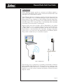
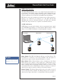
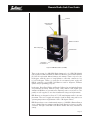
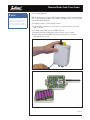
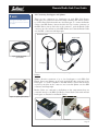
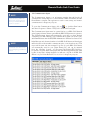
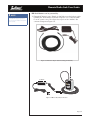
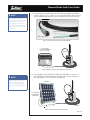
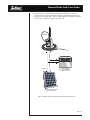
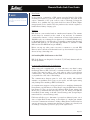
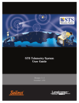
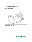
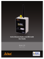
Solinst Remote Radio Link (RRL Gold)
User Guide
Version 1.4.0
August 21, 2014
© 2014 Solinst Canada Ltd. All rights reserved. Printed in Canada.
Solinst and Levelogger are registered trademarks of Solinst Canada Ltd.
All other trademarks and registered trademarks are the property of their respective owners.
Remote Radio Link User Guide
1 Introduction
1
2 RRL Gold Overview
2
2.1 RRL Gold Stations
2
2.1.1 Installing Batteries
2.2 Connecting Leveloggers and Splitters
4
5
Splitters5
3 STS/RRL Gold Software
6
3.1 System Requirements
6
3.2 Software Installation
6
3.3 Communication Agent
7
4 RRL Network Configuration
4.1 Software Administrator Window 4.2 Programming a RRL Gold Network (Software Wizard)
9
9
11
Step 1: Create New Site
11
Step 2: Network Configuration
11
Step 3: Configuration Progress
14
Step 4: Programming Your RRL Gold Station
15
Step 5: Configuring Attached Leveloggers
16
4.2.1 Editing Levelogger Information 17
Setting Up Levelogger Measurement Parameters
19
Step 6: Confirm Station Settings
22
Step 7: RRL Network Configuration Summary
24
4.2.2 Editing RRL Gold Networks
25
Editing the Network Setup
25
Editing RRL Stations
27
5 RRL Remote Utility
28
5.1 Self Test
30
5.2 Firmware Upgrade Instructions
31
6 RRL Gold Station Hardware Setup
6.1 Power Sources and Antennas
32
33
Power Supply
33
Solar Panels
37
Antennas37
6.2 Installing RRL Gold Stations in the Field
Location and Communication Considerations
7 Viewing Site Data
Access Database
View Using STS/RRL Software
37
37
38
38
39
7.1 Barometric Compensation
40
7.2 Graphing Options
42
7.3 File Export 43
Export All Data
44
Remote Radio Link User Guide
1 Introduction
Solinst Telemetry Systems provide an economical and efficient method to
access remote data instantly. They provide communication between field located
dataloggers and a Home Station computer.
Solinst Telemetry Systems are designed specifically for the high quality Levelogger
series of dataloggers. Up to four Solinst dataloggers can be connected to one
Remote Station, in any combination of the Levelogger Edge, Barologger Edge,
Levelogger Junior Edge, LTC Levelogger Junior, Rainlogger Edge, Levelogger
Gold, Barologger Gold, Levelogger Junior, and Rainlogger. (See Levelogger
User Guide for more information on Leveloggers).
Systems operate on two basic schedules. A linear “Sample Rate” is set, at which
a Remote Station records a real-time reading from each attached datalogger.
A “Report Rate” is set to establish the frequency that the data is sent from a
Remote Station to the Home Station PC. Optionally, Leveloggers themselves
can be set up to record and store data independently of the Telemetry System.
This provides a reliable back-up if circumstances require it.
Figure 1-1 RRL System
This manual focuses on configuration, programming, and installation of Remote
Radio Link (RRL Gold) Systems. It also discusses the various options to power
the Systems. It includes instructions for installing and using STS/RRL Gold
Software to set up data collection schedules, manage data, and perform remote
diagnostic checks.
Page 1
Remote Radio Link User Guide
2 RRL Gold Overview
The Solinst RRL Gold System offers a very simple and inexpensive method of
local telemetry. The wireless system is designed to collect real-time data and
send it via radio to your Home Station PC. The RRL is excellent for small,
closed-loop networks such as mine sites and landfill monitoring networks.
RRL Stations work with omnidirectional antennas line-of-sight transmission,
therefore, can communicate over distances up to 20 miles (30 km) with
900 MHz radios and up to 10 miles (16 km) for 2.4 GHz radios. Optional
antennas and using some stations as repeaters can maximize distances.
2.1 RRL Gold Stations
All RRL Stations use the same hardware, and are programmed using a wizard
in the STS/RRL Gold Software as a Home Station, Remote Station or Relay
Station. As such, RRL Gold Stations are interchangeable as required.
Home Station
Relay Station
Remote Station
Figure 2-1 RRL Gold Network
NOTE
The RRL Gold Home Station and
Relay Stations require an external
power supply, as well as the internal
batteries.
Home Station: Each RRL Gold Network will have one Home Station. The
Home Station is connected to a PC using an RS232 cable and requires an
external power supply, as well as the internal batteries, to operate.
Relay Station: When a Remote Station cannot communicate to the Home
Station directly, due to distance or line-of-sight issues, a Relay Station can be
used to transmit the data. Data from attached Leveloggers is stored at a Relay
Station. However, with no Leveloggers attached, data is not stored, it is only
re-transmitted. The radio at a Relay Station is always on, therefore a continuous
external power supply is required, in addition to the internal batteries.
Remote Station: The Remote Station will turn the radio module on and off
based on the Report Rate scheduled. The Remote Station does not require an
external power supply, unless there is a frequent Report Rate programmed.
Page 2
Remote Radio Link User Guide
Antenna
External Power
Connection
RS232 Connection
LED Activity Light
Serial Number
Levelogger
Connections
Figure 2-2 RRL Gold Station (2.4 GHz)
There is the option of a 900 MHz (North American) or 2.4 GHz (Worldwide)
radio module for RRL Gold Stations. RRL Gold Stations come standard with six
(6) 3.6V AA replaceable lithium batteries and antenna. There is input for two
Leveloggers, with the option of using Splitters to allow the connection of up
to four Leveloggers. There is a connection for an external power supply; the
RS232 connection on each RRL Gold Station is used for diagnostic, firmware
updates and programming purposes.
Leveloggers, Direct Read Cables and Reader Cables to be used with the System
are purchased separately. External power cables, RS232 cable, higher gain
antenna and Splitters are optional extras. External power sources (such as solar
panels) are user supplied, as are other installation housings and requirements.
RRL Stations are designed to fit into 4.5" (115 mm) diameter wells for discrete
placement. The case is rugged and waterproof with an IP66 rating and has an
operating temperature range between -20 to +50 degrees Celsius.
RRL Stations have a non-volatile internal memory of 128 KB. A Remote Station
stores collected data in its memory until the Home Station has been successfully
contacted. The light on the RRL Gold Station flashes with every transmission
activity.
Page 3
Remote Radio Link User Guide
NOTE
When replacing the lithium
batteries, wait 1 minute after
removing the old batteries before
installing the new batteries. Do
not wait more than three minutes
before installing the new batteries.
2.1.1 Installing Batteries
RRL Gold Stations are shipped with separate batteries, which must be installed
before programming the Station. Each RRL Gold Station uses six (6) 3.6V AA
replaceable lithium batteries.
To install the batteries, follow the steps below:
1) Use a Phillips screwdriver to undo the four screws from the back of the
RRL Gold unit.
2) Carefully remove the back of the RRL Gold unit.
3) Install the batteries in the battery holder. Ensure proper polarity.
4) Replace the back of the RRL Gold unit ensuring all wires are inside.
Reinstall the four screws.
Figure 2-3 Installing RRL Gold Batteries
Page 4
Remote Radio Link User Guide
NOTE
For more information on installing
Leveloggers in the field, see the
Levelogger User Guide or STS Gold
User Guide.
2.2 Connecting Leveloggers and Splitters
There are two connections for Leveloggers on each RRL Gold Station.
Leveloggers are connected to the station using a Reader Cable, which connects
to a Direct Read Cable threaded onto the Levelogger. To connect the Reader
Cables to the RRL Station, remove the black dust cap from the connection on
the RRL Station, line up the holes in the connectors, push the Reader Cable
connector into the connection on the RRL Station and screw the Reader Cable
onto the RRL connection until finger-tight.
Direct Read Cable
Reader Cable
Figure 2-4 Reader Cable
(pt# 109428)
Levelogger
Figure 2-5 Connecting Leveloggers
Splitters
Splitters allow the connection of up to four Leveloggers to each RRL Gold
Station. One or two Splitters can be used, each allowing the connection of two
Leveloggers. To connect a Splitter to the RRL Station, remove the black dust
cap line up the holes in the connectors and screw the Splitter onto the RRL
connection until finger-tight.
Reader Cables are connected to the Splitters in the same manner they are
connected directly to the RRL Gold Station. Direct Read Cables with attached
Leveloggers are threaded to the Reader Cables.
Figure 2-6 Splitter (pt# 109427)
Figure 2-7 Splitter Connection
Page 5
Remote Radio Link User Guide
NOTE
STS/RRL Gold Software
Version 1.4.0 is compatible only
with the latest RRL Gold Firmware
2.000. See Section 5.2 for firmware
upgrade instructions.
NOTE
You must have administrator
privileges on your PC to install STS/
RRL Gold Software.
3 STS/RRL Gold Software
The Home Station computer requires Version 1.4.0 STS/RRL Software or
later (versions previous to 1.1.1 will not support the RRL). The STS/RRL
Administrator Software provides an easy-to-use graphical interface to set up
each RRL Station, specify communication intervals, and define sampling rates
for attached dataloggers. Collected data is stored and viewed using the software;
it can also be exported for use in other programs.
The STS/RRL Communication Agent is automatically installed with the STS/
RRL Administrator Software, and is used to view communication activity.
The RRL Remote Utility is useful to install on a portable laptop, as it provides
a convenient way to communicate with programmed RRL Gold Stations in your
office or in the field, as well as perform remote diagnostic checks and firmware
updates. See Section 5 for more information on the Remote Utility.
3.1 System Requirements
NOTE
STS/RRL Gold Software is also
used to program Solinst STS Gold
Telemetry Systems. See STS Gold
User Guide for more information.
The minimal hardware and software requirements for software installation and
operation are:
Hardware
Memory: 256MB or more
Software
OS: Windows XP, 7, 8
Display: VGA: 800 x 600 pixels, 256 colour
Ports: RS232 Serial Port
Hard Drive space: 64MB
3.2 Software Installation
NOTE
The STS/RRL Communication Agent
should always remain open when
the RRL Gold System is in operation.
It may be closed, but the data can
not be sent to the Home Station
Computer. The data will be stored
in the RRL Gold Remote Station
until the Agent is re-opened, and
not until the next scheduled report .
Web Download
Download the newest version of the STS/RRL Administrator Software
and/or the RRL Remote Utility by visiting www.solinst.com/downloads/
The STS/RRL Communication Agent automatically installs with the STS/RRL
Administrator.
CD Installation
1) Insert the software CD provided.
2) If the installer does not automatically start, to activate the software install
click on the ‘setup.exe’ file located on the software CD.
3) The Software Installation Wizard will guide you through the remaining
installation process. The STS/RRL Administrator, STS/RRL
Communication Agent, and RRL Remote Utility are all automatically
installed.
4) Restart the computer after installation is completed. Default Directory is
<C:\Program Files\Solinst\STS_Gold>
Page 6
Remote Radio Link User Guide
NOTE
The Communication Agent must
be started before your RRL Gold
Network starts logging and must
remain open while the RRL Gold
System is in operation.
3.3 Communication Agent
The Communication Agent is an information window that will display all
communication activity that has occurred between a RRL Gold Station and the
Home Station computer. This application is used to view activity, and monitor
communication for diagnostic purposes.
To open the Communication Agent, click on
, or click the Start button
and select: Programs > Solinst > STS_Gold > STS Gold Com Agent
The Communication Agent must be opened before your RRL Gold Network
starts logging and must remain open while the RRL Gold System is in operation.
The Communication Agent will automatically open after you have finished
configuring your RRL Network. The Communication Agent can be left open,
and minimized even after the STS/RRL Administrator Software has been closed.
NOTE
The Communication Agent will
automatically open after you have
finished configuring your RRL Gold
network.
In the Messages tab, the serial number of each RRL Gold Station and Levelogger
will be shown to indicate which communication has come from that site. Each
report will be time and date stamped. Log files for each RRL Gold Station
are automatically saved on your Home Station PC, and can be retrieved
from the following location: <C:\Program Files\Solinst\STS_Gold\log>
If a station is stopped, when started again, the data will be appended to the same
log file. At any time, clicking the Save icon will save a log file of all RRL Gold
Stations on your Home Station PC for record or for diagnostic purposes.
Figure 3-1 Communication Window
Page 7
Remote Radio Link User Guide
The Site Report Time tab lists each RRL Gold Station by serial number and
shows the next time it is scheduled to report to the Home Station.
If there is a communication conflict and the Remote Station does not report
when scheduled, a timeout message will be shown in the Communication Agent
Messages. To stop receiving timeout messages from a station (you may be aware
of what is causing the communication issue, and do not need the messages any
longer), uncheck the box beside the Station (see below).
Figure 3-2 Communication Window - Site Report Time
Page 8
Remote Radio Link User Guide
4 RRL Network Configuration
To Start the STS/RRL Gold Software, click on
select:
, or click the Start button and
Programs > Solinst > STS_Gold > STS Gold Admin
4.1 Software Administrator Window
NOTE
When opening the Software for the
first time, you will be prompted to
the Network Setup screen before
the Administrator is shown.
After the Software has been started, the Administrator window will open. From
here you can create new RRL Networks, edit existing networks, delete existing
networks, and open site data.
NOTE
STS Gold Telemetry Sites will also be
listed in the Administrator Window.
See separate STS Gold User Guide
for more information on STS
Telemetry Systems.
Figure 4-1 Administrator Window - Network Information
The Menu on the left of the window lists each existing RRL Gold Network by its
project identification and each RRL Gold Station in the network by its location
and serial number (number located on each RRL unit). Selecting a network
from the list will display all of the stations in the network, along with the report
and sampling rates. Selecting a station from the list will display information
on the Station Battery Strength, Station Signal Strength, Last Update Time
and network details (including Project ID, Location, Number of Loggers, etc).
Information for each datalogger connected to the site is displayed, including
instrument type, and battery strength.
Page 9
Remote Radio Link User Guide
NOTE
When setting up your RRL Gold
Network, it is recommended you
print each Station Information
Screen for your records.
Figure 4-2 Administrator Window - Station Information
• Last Update Time: Shows the last time the Home Station was
contacted
• Remote Station Battery: Percentage of strength left in the RRL
Gold Station battery and battery voltage at the RRL Station.
• Remote Station Signal Strength: Signal strength of the radio at
the RRL Gold Station.
• Station Type: Identifies whether the station has been programmed
as a Remote Station, Relay Station, or Home Station.
• Project ID: Your own identification system that you input.
• Location: Specific site / location information you input.
• Number of Loggers: The number of dataloggers that are connected
to the RRL Gold Station.
• Comm Method: Indicates the COM Port that is being used at the
Home Station computer for communication.
• Sampling Information: Shows the Sample Rate of the RRL Station.
• Site Status: Will show the status of the RRL Station, i.e. “Logging”,
“Waiting for Update”.
Page 10
Remote Radio Link User Guide
4.2 Programming a RRL Gold Network (Software Wizard)
Step 1: Create New Site
Selecting “New” in the Administrator window main menu opens the Network
Setup Screen. It will also open when the software is started for the first time.
This is where you choose to set up an STS Gold Site or RRL Gold Network,
which will start the software wizard.
NOTE
When opening the software for the
first time, you will be prompted to
the Network Setup screen before
the Administrator is shown.
NOTE
It is recommended you connect
your Leveloggers to each RRL Gold
Station before programming.
Figure 4-3 Network Setup Screen
Step 2: Network Configuration
After you select “RRL Gold Site”, the RRL Network Setup screen will open. In
this screen you will enter the settings for your RRL Gold Network.
•
•
•
Project Identification: Input the unique name you choose to identify
your project/site.
Network ID: Select a number to identify the network. There may be
more than one network reporting to the same Home Station
computer. There can be a maximum of 5 networks reporting to the
same Home Station. This is to avoid radio communication conflict between adjacent networks. Each RRL Gold Station in the same
network should use the same ID number.
Radio Frequency: Select the frequency of your RRL radio modules.
Either 900 MHz or 2.4 GHz.
Page 11
Remote Radio Link User Guide
Figure 4-4 RRL Network Setup Screen
NOTE
If a higher Radio Power setting is
selected, the battery at the RRL
Gold Station will be drained more
quickly, therefore you may require
an external power source.
NOTE
If the highest Radio Power setting is
still not adequate to communicate
the distance required, you may
need a more sensitive antenna or
the addition of a Relay Station.
• Radio Power: This option is used for 900 MHz radios. Selecting
a lower power setting can reduce power consumption, however,
the communication distance is directly proportional to the radio
power. Choose 100 mW to maximize battery life. Choose 1W to
maximize the communication distance.
• Master Com Port: Identify the Com Port being used for
communication between the computer and the Home RRL Station.
• Number of Home Stations: This is always 1.
• Number of Relay Stations: Enter the number of Relay Stations in
your network.
• Number of Remote Stations: Enter the number of Remote Stations
in your network.
• Network Start Time: Enter the date and time your RRL
Remote Stations will begin collecting data from the attached
Leveloggers.
• Sample Rate: Is the frequency the RRL Remote Stations collect
real-time readings from each of the attached Leveloggers. The
Sample Rate can be set from 10 seconds to 99 hours. You can
choose to set each station with a different Sample Rate. This can
be done in Step 4 when you are setting up each individual station,
otherwise all stations will have the same sampling rate as set in this
step.
Page 12
Remote Radio Link User Guide
NOTE
Longer Report Rate intervals will
conserve battery power at Remote
Stations.
NOTE
If your Reporting Rate is less than 3
hours, an external power source is
recommended.
Report Rate and Report Duration are important if multiple RRL Gold Stations
will be reporting to one Home Station. Setting up a schedule will avoid conflicts
that may occur if more than one RRL Station contacts the Home Station at the
same time.
•
•
Report Rate is the rate at which stored data is sent from a Remote
Station to the Home Station. The Report Rate can be set
from 1 minute to 99 hours.
Report Duration is the maximum span of time that a Remote
Station will be in contact with the Home Station during the
transfer of data. The minimum Report Duration is 1 minute.
Example:
If you have three Remote Stations reporting to one Home Station, all with a
Report Rate of 15 minutes, you will want to set a Report Duration of 5 minutes
(or less) for each RRL Station. This ensures that each Remote Station has enough
time to send the data within the 15 minutes allotted on the Home Station.
If you have set a Network Start Time of 12:00 PM, your RRL Remote Stations
will begin collecting data at 12:00 PM. At 12:15, the first Remote Station will
report its data; the second will report data at 12:20 PM, and the third at 12:25.
Page 13
Remote Radio Link User Guide
Step 3: Configuration Progress
Figure 4-5 RRL Gold Software Wizard Transition Screen
Step 3 is a transition screen. At this point you should connect the RRL Gold
Station you are about to program to the Home Station computer using an
RS232 cable (#106811). This screen will identify that you are about to program
the Home Station, a Relay Station or Remote Station. Programming the Home
Station is always first. This screen will show you your progress in configuring
your RRL Network. It will indicate which RRL Stations have been programmed
and which RRL Stations are left to program.
#106811
Figure 4-6 RRL Station Connected to a PC
Page 14
Remote Radio Link User Guide
Step 4: Programming Your RRL Gold Station
In Step 4, enter the serial number of the RRL Gold Station you are programming;
the Location of the Station, i.e.: “Home Station”, “Well 1”, “Relay Station 2”;
the Com Port being used to program the RRL Station; and the Sample Rate for
that station (if different from the one set in Step 2).
If you are programming the Home Station, you will select whether there is a
Levelogger connected to the station. If there is not, you will skip to Step 6. If
there is a Levelogger connected, or you are programming a Remote Station,
you will proceed to Step 5.
Figure 4-7 Programming a RRL Gold Station
Page 15
Remote Radio Link User Guide
Step 5: Configuring Attached Leveloggers
In this step you will select the number and types of Leveloggers connected to the
RRL Gold Station.
The connectors for Leveloggers on the RRL Gold Stations are identified as Right
and Left. This assumes the RRL Station is facing with the black label towards
you. If using a Splitter, the number 1 or 2 will identify the Leveloggers. The
numbers 1 and 2 are labeled directly on the connections of each Splitter.
NOTE
If you are connecting a Rainlogger,
you must program (Edit) it in order
to enter a Rainfall Calibration
Constant (the amount of rainfall per
tip of the connected rain gauge).
For each connection you will select the type of Levelogger attached. Select ‘None’
for connectors with no Levelogger attached. After selecting the datalogger type
from the drop down menu, an image of the selected datalogger will be displayed.
To optionally set each datalogger to record in their internal memory, select Edit
to begin entering data collection information.
You must Edit the Rainlogger in order to enter a Rainfall Calibration Constant,
but you do not have to set it to record independently.
Select Next, without editing, if you do not want to set your Leveloggers to record
independently.
NOTE
The firmware versions shown in
red for each Levelogger, are the
firmware versions that will work
with STS/RRL Software Version 1.4.0.
Figure 4-8 Adding Leveloggers
Page 16
Remote Radio Link User Guide
NOTE
If you want your datalogger to
record and store readings in its
internal memory, independent of
RRL operation, select
NOTE
To stop the Levelogger from
independently logging,
select
Figure 4-9 Levelogger Information Window
4.2.1 Editing Levelogger Information
NOTE
If you are programming a number
of Leveloggers with the same
settings, select “Save Settings” after
programming the first Levelogger.
Select “Load Settings” when starting
to set up your next Levelogger to
apply the saved settings.
NOTE
The Levelogger Edge, Levelogger
Junior Edge and Barologger Edge
can be adjusted for Altitude and
Density post data collection using
the Data Compensation Wizard in
the Levelogger Software.
The Levelogger Information window includes Levelogger Serial Number, Well
Location, Altitude and Density Adjustment (Levelogger Gold and Junior models
only), Sample Rate, and Memory Mode Selection.
If you want your datalogger to record and store readings in its internal memory,
independent of RRL operation, select
, and fill in the Sample Rate and
Memory Mode Selection fields.
If you do not require independent logging, select
, and the RRL Station
will only collect a real-time reading from the Levelogger at the scheduled Sample
Rate. There is no need to enter a Levelogger Sample Rate.
•
•
•
•
Serial Number: Your Levelogger Serial Number will display after the
System is started.
Well Location: Input specific site / location information.
Density Adjustment: (Levelogger Gold and Junior models only) Is
used to adjust the range of the Levelogger based on the sample fluid
density. The range for the density adjustment is from 0.9 kg/L to
1.1 kg/L. Uncheck the Density Adjustment field to disable the
Density Adjustment function.
Altitude: (Levelogger Gold and Junior models only) In feet or meters
above sea level, at which the logger is actually deployed, is input
in the altitude field. Water column equivalent pressure decreases with
altitude at a rate of approximately 1.2:1000 in the lower atmosphere
below 5000 m. You can compensate for this by entering an elevation
Page 17
Remote Radio Link User Guide
NOTE
The default sample rate is set to 15
minutes.
NOTE
The LTC Levelogger Junior has
a minimum sampling rate of 5
seconds. The Levelogger Gold and
Levelogger Junior can be set from
0.5 seconds to 99 hours.
•
•
between -1000 ft below sea level and 16,400 ft (or -300 m and
5000 m) above sea level. The readings will then be automatically
compensated for elevation.
Sample Rate: Is linear. Linear refers to a set time interval between
collection of readings. Sample Rate can be any number from 0.125
seconds to 99 hours for the Levelogger Edge. The Levelogger Junior Edge can be set to record from 0.5 seconds to 99 hours.
Memory Mode Selection: There is a choice of Continuous Logging
(wrap around) or Slate Logging. In Continuous Logging the new log
is started at the end of any previous log and continues logging,
eventually recording over the first logged data. As one of the
download options is to ‘Append Data’, Continuous Logging can be
a preferred choice when logging long-term. In Slate Logging the
new log is also started at the end of any previous log, but will store
recordings when the memory is full, so that the beginning of the
current log will not be written over. The Levelogger Junior Edge, LTC
Levelogger Junior, Rainlogger, and Levelogger Junior only record in
Slate Mode.
NOTE
In Slate Logging, the datalogger
will stop recording readings after
its memory is full. Therefore,
Continuous Logging is
recommended for long term
monitoring applications.
Page 18
Remote Radio Link User Guide
Setting Up Levelogger Measurement Parameters
In the lower portion of the Levelogger Information screen is the window for
setting channel parameters. The software will detect the available channels when
the Levelogger Information settings are read.
NOTE
The only units available for the
Levelogger Junior, LTC Levelogger
Junior, Levelogger Gold and
Barologger Gold are m (default), cm,
and ft.
For the Level Channel, you can set the following parameters:
•
•
•
Identification describes the measurement parameter of the channel
and has already been configured as ‘LEVEL’. The Level Channel
monitors water column equivalent pressure. The Identification field
will be the data column heading and graph line name when viewing
the data.
Units refers to the channel’s units of measurement. There are six
units of measure available for the user to select: m (default), cm, ft,
kPa, mbar, and psi. When using a Barologger Edge, the options are
kPa (default), mbar, and psi.
Offset refers to an offset correction, such as the distance between the
tip of the Levelogger and the monitoring well cap or static water
level. It is recommended that the value of 0.00 be used for offset as
this keeps all subsequent readings relative to the tip of the Levelogger.
The offset range is -1000 to 16400 ft or -300 m to 5000 m.
The Temperature Channel includes the following parameters:
NOTE
The Levelogger Junior, LTC
Levelogger Junior, Levelogger Gold
and Barologger Gold only measure
in ºC.
•
•
Identification describes the measurement parameter of the channel
and has already been configured as ‘TEMPERATURE’
Units refers to the channel’s units of measurement. For the
Levelogger and Barologger Edge, the temperature channel can be set
to ºC (default) or ºF.
Figure 4-10 The Temperature Channel
Page 19
Remote Radio Link User Guide
NOTE
To calibrate the LTC Levelogger
Junior, use Levelogger Software
Version 4.0 or higher. The LTC
Levelogger Junior should be
calibrated before starting any new
project.
NOTE
Conductivity measurements can be
converted to Specific Conductance
measurements or Salinity values
using the Data Compensation
Wizard in the Levelogger Software.
LTC Levelogger Junior Measurement Parameters:
• Identification describes the measurement parameter of the channel
and has already been configured as ‘Conductivity’ .The Identification
field will be the channel heading, data column heading and graph line
name when viewing the data.
• Unit refers to the channel’s units of measurement. There are two
units of measure available for the user to select: mS/cm or μS/cm.
• The Temperature Coefficient field allows you to choose the actual
conductivity (‘Conductivity’) at the current temperature or select
Specific Conductance (‘Spec. Cond’.) measurement in which the
conductivity reading is temperature compensated to the standard
of 25ºC. The Temperature Coefficient default is 2.00 for Specific
Conductance readings. The Temperature Coefficient should not
be adjusted, unless you know the value specific to the solution you are
measuring.
Figure 4-11 LTC Levelogger Junior Measurement Parameters
Page 20
Remote Radio Link User Guide
NOTE
Your Rainlogger Edge must be using
firmware version 3.000 or higher.
Your Rainlogger firmware must be
upgraded to 2.000 or higher.
NOTE
The Sample Rate and Max Rainfall
options included in Rainlogger
firmware versions previous to 2.000,
are no longer available.
NOTE
You must program (Edit) your
Rainlogger in order to enter a
Rainfall Cal Constant (the amount of
rainfall per tip of the connected rain
gauge), but you do not have to set
it to record independently.
Rainlogger Measurement Parameters:
There is one channel of measurement for Rainloggers. The ‘RainFall’ Channel
records each tip time by the connected tipping-bucket and outputs the amount of
rainfall per tip (input Rainfall Cal Constant). When an RRL Gold Remote Station
reports Rainlogger data to the Home Station, it will send the accumulated rainfall
amount per sample period (based on RRL Station Sample Rate). To determine
the exact time that a tip occurred, the Rainlogger would have to be set to record
in its own internal memory, which stores each tip event.
• Identification describes the measurement parameter of the channel
and has already been configured as ‘RainFall’. The channel can be
re-named to suit each project. The Identification field will be the
channel heading, data column heading and graph line name when
viewing the data. Identification is limited to 32 characters.
• Units refers to the channel’s unit of measurement. There are two
units of measure available for the user to select: mm or in.
• The Rainfall Cal Constant field allows you to enter the calibration
factor for the tipping-bucket you will be using. The calibration factor
is the amount of rainfall depth (mm, in) per tip. The calibration factor
should be indicated on a label on the tipping-bucket device or in the
manufacturer’s documentation. Input the calibration factor in mm or
inches.
NOTE
When an RRL Gold reports
Rainlogger data to the Home
Station, it will send the accumulated
rainfall per sample period (based on
RRL Station Sample Rate).
Figure 4-12 Rainlogger Measurement Parameters
After all Leveloggers have been entered and programmed as desired, proceed
to Step 6.
Page 21
Remote Radio Link User Guide
Step 6: Confirm Station Settings
In this step, select “Retrieve RRL Info”. This will apply all the settings to the RRL
Gold Station and retrieve information from that station to confirm it has been
successfully programmed.
Figure 4-13 RRL Station Information
•
•
•
•
Serial Number: Should match the serial number you entered
in Step 2.
Battery Level: The internal battery level of the RRL Gold Station
System Time: The internal system time of the RRL Gold Station
Status: The RRL Station is “Logging” or “Waiting for Update”.
You will also select whether you wish to start this station using the Programmed
Start Time entered in Step 2, or use the Remote Utility to start the station at a
different time (see Section 5).
•
•
Sampling based on the Future Start Time: The RRL Gold Station
will start sampling based on the start time you set in Step 2.
Use RRL Remote Utility to Start Sampling: The RRL Gold Station
will stay in stop mode. To start sampling, you have to use the RRL
Remote Utility (see Section 5).
If you are programming the Home Station or one of multiple Remote or Relay
Stations, you will be prompted to the transition screen in Step 3. This will show
which stations have been programmed, and which stations are left to program.
Stations that have been programmed will be identified as “Done”.
You will proceed through Steps 3 to 6 until all stations have been programmed.
See Figures 4-14 and 4-15.
Page 22
Remote Radio Link User Guide
Figure 4-14 Configuring a Relay Station
Figure 4-15 Configuring a Remote Station
Page 23
Remote Radio Link User Guide
Step 7: RRL Network Configuration Summary
Figure 4-16 RRL Network Configuration Summary
After all settings have been programmed for each RRL Gold Station in the
network, Step 7 will display a summary of all the settings. You can print a copy
of this summary for your records.
Selecting ‘Finished’ will open the STS Administrator window and start the
Communication Agent.
NOTE
Once all stations have been
programmed, it is recommended
you start each station logging as
a test in the office. This can be
done using the Remote Utility (see
Section 5).
After each station is started, and
has contacted the Home Station,
the serial numbers and types of
Loggers connected to the station
will be shown in the Administrator
Window. You can print a copy
of this screen for each station
as a record, and refer to it when
installing your stations in the field.
Figure 4-17 RRL Network in Administrator Window
Page 24
Remote Radio Link User Guide
NOTE
Selecting “Delete” when a RRL Gold
Network is highlighted, will not
allow you to delete that network,
until all stations in that network are
deleted first.
4.2.2 Editing RRL Gold Networks
Editing the Network Setup
When you select a RRL Gold Network from the list in the STS Administrator
window, choosing “Edit Site Setup” will allow you to “Edit Network Setup” or
“Add new Site to Network”.
Figure 4-18 Editing a RRL Gold Network
When you select “Edit Network Setup” there are two options. You can choose
to update each RRL Gold Station in the network by connecting them to the PC
through the RS232 Port, or the “Remote Schedule Update” allows you to make
the changes in the software, and the new settings will be applied to each RRL
Gold Station with their next scheduled report to the Home Station.
If you choose “Remote Schedule Update”, there are two steps. Step 1 allows
you to make changes to the network settings, including: Project Identification,
Network ID, and Radio Power. You can also restart the network with a new
Sampling Rate, Report Rate, and Report Duration.
Figure 4-19 Editing a RRL Gold Network - Step 1
Page 25
Remote Radio Link User Guide
NOTE
The screenshot at right shows 4
steps. This is because the option
to update each RRL Gold Station
through the serial port was selected.
Steps 2 and 3 in this case are for
connecting the two Remote RRL
Gold Stations in the network, to the
PC and updating their settings. Step
4 provides the summary.
Figure 4-20 Editing a RRL Gold Network - Step 2
Step 2 will provide you with a new Network Configuration Summary that you
can print for your records.
If you select to update each RRL Gold Station through the serial port, after
changing the setting in Step 1, you will be prompted to connect each RRL
Gold Station to the Home Station PC with an RS232 cable, and update them
with the new network settings. The last step will provide you with a Network
Configuration Summary for your records.
When you select “Add new Site to Network”, you will be prompted though Steps
2 through 7 of the software wizard.
Page 26
Remote Radio Link User Guide
NOTE
Selecting “Delete” when a RRL Gold
Station is highlighted will prompt
a window asking if you are sure
you want to delete that station.
You must delete all stations in a site
before the entire network can be
deleted.
Editing RRL Stations
When you select a specific RRL Gold Station from the list in the STS Administrator
window, choosing “Edit Site Setup” will allow you to edit the settings for that
RRL Station.
Figure 4-21 Editing a RRL Station
There are three steps when editing a RRL Gold Station’s settings. Step 1 allows
you to enter a new Location, Program Com Port and Sample Rate. Step 2 allows
you to add or edit the attached Leveloggers and their settings. Step 3 retrieves
the new settings and allows you to choose between applying the changes to
the RRL Station by connecting it to the PC, or the “Remote Schedule Update”
allows you to make the changes in the software, and the new settings will be
applied to the RRL Station with its next scheduled report to the Home Station.
Figure 4-22 Editing a RRL Gold Station - Steps 1 and 3
Page 27
Remote Radio Link User Guide
NOTE
RRL Remote Utility Version 1.3.0
should be used with STS/RRL
Software Version 1.4.0.
5 RRL Remote Utility
The RRL Remote Utility provides a convenient way to communicate with
programmed RRL Gold Stations in your office or in the field, as well as perform
diagnostic checks and firmware updates.
Figure 5-1 RRL Remote Utility
To open the RRL Remote Utility, click
, or click the Start button and select:
Programs > Solinst > rrlg_remote > RRL Remote Utility
The RRL Remote Utility can be used to test radio communication between
a Remote or Relay Station and the Home Station, check RRL Gold Station
settings and status, test communication with the attached Leveloggers, and stop
or start the RRL Station logging (when selected in Step 2 of the software wizard).
The Remote Utility also includes a self-test function. The function performs a
series of self-tests on a RRL Gold Station to check for problems with the battery,
memory, etc.
To use the RRL Remote Utility, connect the RRL Gold Station to a PC with a
RS232 cable, select the COM port to which the Station is connected and click
“Retrieve Info” to display the settings from the RRL Gold Station.
Page 28
Remote Radio Link User Guide
NOTE
The Radio Communication Test is a
convenient tool when determining
the final location of you Remote
Station in the field and the proper
Radio Power setting for that station.
The Remote Utility has the following functions:
•
Radio Communication Test: Click “Radio Test” to initiate the test.
If the communication between the RRL Gold Station and the Home
Station is successful, the “Home Station Communication Test Passed”
message will be shown.
Figure 5-2 Home Station Communication Test
• Datalogger Communication Test: Click the Test button beside the
datalogger image to initiate the test. If the communication is
successful, the “Probe Communication Test Passed” message will be
shown.
Figure 5-3 Datalogger Communication Test
•
Start Logging: If the RRL Gold Station is in idle mode “Start” will
be displayed in the Remote Utility main menu.
To start logging, click “Start”, and “Stop” will then be
displayed to indicate that the RRL Gold Station is in logging mode.
•
Stop Logging: If the RRL Gold Station is in logging mode “Stop”
will be displayed in the Remote Utility main menu.
To stop logging, click “Stop”. A message “Data Logging
and Reporting will be terminated. Do you want to continue?” will be
shown. Click Yes to continue.
“Start” will be displayed to indicate that the RRL Gold Station is in
idle mode.
Page 29
Remote Radio Link User Guide
5.1 Self Test
The Remote Utility also includes a self-test function. The function performs a
series of tests on a RRL Gold Station to check for problems with the battery,
memory, etc. If any of these tests fail, then a report should be created and sent
to Solinst Technical Support. To execute this function, select “Self Test”.
Figure 5-4 RRL Gold Station Self Test
Page 30
Remote Radio Link User Guide
NOTE
STS/RRL Gold Software Version 1.4.0
is compatible only with the latest
RRL Gold Firmware 2.000.
5.2 Firmware Upgrade Instructions
RRL Gold Stations have been designed with firmware that is easy to update
whenever useful new functions or other improvements become available, as
with software releases. To determine the current firmware version on an RRL
unit, connect it to the PC with a RS232 cable and open the RRL Remote Utility.
Select the COM port to which the unit is connected and click “Retrieve Info” to
display the settings, including firmware version, from the RRL Station.
To update the firmware in your RRL Gold Station, go to the Solinst Website at:
http://www.solinst.com/Downloads/ where you can obtain a link to the RRL
firmware update file that is contained within a Zip Archive. Ensure you unzip the
archive to access the *.ssf firmware file.
1) Use an RS232 serial cable to connect the RRL Gold Station to the PC.
2) Ensure you have installed the RRL Remote Utility Software on your PC.
There will be a Firmware Upgrade Utility shortcut added to your desktop.
3) Open the Firmware Upgrade Utility and make sure the Baud Rate is set to
9600.
4) Click the ‘Open’ button, which should open a file dialog asking for the
firmware file (*.ssf) to upload. Navigate to where the firmware file was
saved on your PC, then click on the file and click ‘Open’.
5) Check the ‘Firmware File Information’ box to make sure that the opened
file is the right one.
6) Click the ‘Upload Firmware’ button to start the firmware upload process.
7) If a communication error occurs and is indicated in the Information
Window either before the “Verified Program Checksum” message or after
the “Program Information Section”, then restart the upgrade process.
Figure 5-5
Firmware Upgrade Utility
Note: When conducting a firmware upgrade, DO NOT interrupt the process prior
to completion (This may take 30 minutes). If the notice “The firmware version
in the RRL is more recent, continue the firmware updated?” appears, you
must select “Continue”. Selecting “No” or otherwise interrupting the upgrade
process will make the RRL Station unable to communicate with STS/RRL
Software. To correct this, the firmware must be re-upgraded, and allowed to
fully complete installation. Installation is not complete until a note appears at
the base of the program window indicating “Firmware Upgrade Completed”.
Page 31
Remote Radio Link User Guide
NOTE
See Section 2.2 for connecting
Leveloggers and Splitters.
6 RRL Gold Station Hardware Setup
RRL Gold Stations come standard with a built-in radio module. There is the
option of either a 900 MHz (North American) or 2.4 GHz (Worldwide) module.
Also standard is a 6" half wave (2.1 dBi) antenna, six (6) 3.6V AA lithium
batteries, and dust caps to protect connections when not in use.
Dust Cap for External
Power Connection
Antenna (pt# 109459)
(pt# 108950 for 900 MHz)
Dust Cap for
RS232 Connection
Dust Caps for Levelogger
Connections
Batteries (3 x 2 packs)
(pt# 109482)
Figure 6-1 RRL Gold Station (2.4 GHz)
900 MHz Assembly (pt# 109236) or 2.4 GHz Assembly (pt# 109458)
Page 32
Remote Radio Link User Guide
NOTE
The RRL Gold Home Station and
any Relay Station requires an
external power supply.
NOTE
Where possible, use lower Radio
Power settings and/or longer
Report intervals to conserve
Remote Station Battery life.
6.1 Power Sources and Antennas
Power Supply
RRL Stations come standard with six (6) 3.6V AA lithium batteries.
The batteries must be installed for proper operation, even if you use an
additional external power source. The life of the battery varies depending on the
frequency of your Sample and Report Rates. The following are estimates based
on the standard lithium batteries, with the Radio Power setting at 1 Watt. With
the Radio Power set at 100 mW, the battery life increases by about 10% of the
estimates below. RRL Gold Stations can also be powered by six (6) user-supplied
1.5V AA alkaline batteries. With alkaline batteries, the battery life will be about
40% of the estimates below.
Sample Rate
NOTE
If your Reporting Rate is less than 3
hours, an external power source is
recommended.
Report Rate
Battery Life
Every 5 Minutes
Every Hour
114 Days
Every 15 Minutes
Every 6 Hours
425 Days
Every Hour
Every 12 Hours
680 Days
Every 12 Hours
Every Day
895 Days
Every 15 Minutes
Every 3 Days
810 days
Every Hour
Every 7 Days
1078 Days
Every 12 Hours
Every 14 Days
1200 Days
Table 6-1 Battery Life Estimates (6 AA lithium batteries at 1 Watt setting)
NOTE
The internal RRL Gold batteries are
not rechargeable.
RRL Gold Home Stations and Relay Stations require an external power
supply. Remote Stations may also require an external power supply, depending
on your Sample and Report Rates and site needs. Solinst supplies a cable for
connecting to an AC power source and a cable to connect to a user-supplied
12V battery or solar panel. Cables are connected to the RRL Gold Station beside
the antenna connection (see Figure 6-2).
NOTE
Rechargeable batteries can not be
used inside any RRL Units (Home,
Relay, Remote), as the voltage
would be to low.
Figure 6-2 External Power Cable Connection
Page 33
Remote Radio Link User Guide
NOTE
The six (6) 3.6V AA batteries must
be installed for proper operation,
even if using an additional external
power source.
RRL Gold Stations can be powered by:
1. External AC (mains) power. Simply use the Solinst supplied adaptor cable
(pt#109720 - North American) shown in Figure 6-3 to connect the RRL
to an AC power source. The adaptor has input from 90 - 246VAC. See
connection diagram in Figure 6-4.
Figure 6-3 AC Power Adaptor Cable Assembly (pt# 109720)
#109720
Figure 6-4 Direct AC (mains) Connection
Page 34
Remote Radio Link User Guide
NOTE
The external 12V battery should
have a minimum 60 Amp-hour
rating. It is recommended you have
a higher Amp-hour rating if you
have a high report rate, or if your
station is in a very remote location
and you are not able to replace the
battery easily.
2. Using the Solinst-supplied Solar/12 Volt Cable Assembly (pt# 109452),
shown in Figure 6-5, to connect to a user-supplied external 12V lead-acid
battery (minimum 60 Amp-hour). See connection diagram in Figure 6-6.
- (Ground Connection)
RRL Connection
+ (12V Connection)
Figure 6-5 Solar/12V Cable Assembly (pt# 109452)
User-supplied
12V Lead Acid Battery
60 Amp-hour Min.
#109452
Figure 6-6 External 12V Lead-Acid Battery Connection
NOTE
Solar panel power will not be
available at night or during very
cloudy conditions. If Reporting
sessions are scheduled for these
times, the internal batteries will be
used.
3. Using the Solar/12 Volt Cable Assembly (pt# 109452) to connect to a
user-supplied Solar Panel (minimum 15 watt) with a built-in regulator for
12V. See Figure 6-7 for the connection diagrams.
15W Min.
User-supplied
12V Regulated
Solar Panel
+
-
#109452
Figure 6-7 External Solar Panel Connection
Page 35
Remote Radio Link User Guide
4. Using the Solar/12 Volt Cable Assembly (pt# 109452) to connect to
an external user-supplied 12V lead-acid battery (minimum 12 Amp-hour
rating), trickle charged with a Solar Panel (minimum 15 W with a regulator
for 12V). See connection diagram in Figure 6-8.
#109452
15W Min.
User-supplied
12V Lead Acid Battery
12 Amp-hour Min.
User-supplied Solar Panel
with 12V Regulator
Figure 6-8 External 12V Lead-Acid Battery with Solar Panel Connection
Page 36
Remote Radio Link User Guide
NOTE
For more information on installing
Leveloggers in the field, see the
Levelogger User Guide or STS Gold
User Guide.
Solar Panels
A solar panel is connected to a RRL station using the Solar/12 Volt Cable
Assembly (see Figure 6-7). The solar panel is user-supplied. The panel should
output a minimum of 13V open circuit in order to effectively re-charge the
batteries. As a guideline, the solar panel should be at least 15 Watts. Higher
wattage panels are also suitable. The solar panel must also include a regulator to
handle external battery charging cycle.
Antennas
RRL Stations come standard with an omnidirectional antenna. The antenna
should always be mounted on the outside of any enclosure for maximum
communication distance, as they communicate via line-of-sight transmission.
900 MHz radios can communicate over distances up to 20 miles (30 km) and up
to 10 miles (16 km) for 2.4 GHz radios. To maximize communication distances
between RRL Stations, an optional High Gain Antenna is available for 900
MHz and 2.4 GHz RRL Stations (pt# 108987).
Before sourcing any other power accessories or antennas to use with RRL
Stations, refer to the radio module manufacturer’s product manuals for approved
devices at: http://www.digi.com.
6.2 Installing RRL Gold Stations in the Field
RRL Gold Stations are designed to fit inside 4.5" (115 mm) diameter wells for
discrete placement.
Location and Communication Considerations
When using radio communication, you must take extra care when locating
the Remote Stations. RRL Gold radios communicate with each other via lineof-sight. They must be able to “see” each other in order to have effective
communication. The path between radio antennas should not be through trees
or perpendicular to the sides of flat buildings.
The communication distances given for each radio module, with standard
antennas, are guidelines. Each project is site specific, and will require testing
and planning before installing a RRL Gold Network.
A communication range test can be performed prior to installation between the
Home Station and the Remote or Relay Station using the RRL Remote Utility
(see Section 5). Tests can be done using different Radio Power settings (see
Section 4.1) to determine the ideal setup for your site. Always start with the
lowest Radio Power setting, as this will conserve battery power. (Longer Report
intervals will also conserve battery power).
Field tests will allow you to determine if you need an additional power source
due to a higher Radio Power setting, or the addition of a higher gain antenna
to increase communication distances. Adding a Relay Station should be the last
option to increase your communication distance, or if there is an obstacle (such
as buildings or trees) that you have to get your RF signal around.
Page 37
Remote Radio Link User Guide
7 Viewing Site Data
Access Database
NOTE
The Access database can be queried
by your own macros or applications,
to automatically check for updates
and display the data in your own
program, on a website, or in any
way you choose.
Data received in each report from a RRL Gold Station is placed in a Microsoft®
Access® database (.mdb files) on the Home Station computer. New data is
appended to the existing database. The program will save data downloaded to
the following default directory: <C:\Program Files\Solinst\STS_Gold\db>
Figure 7-1 RRL Gold Database Folder
Figure 7-2 RRL Gold Access Files
Figure 7-3 RRL Gold Access Data
Page 38
Remote Radio Link User Guide
View Using STS/RRL Software
The STS/RRL Gold Software can be used for a quick check of the latest readings.
Data can also be exported using the Software as *.xle, *.lev or *.csv files for use
in other programs.
To view data from a specific site using the STS/RRL Gold Software, open the
Administrator window and select a RRL Network or station from the list. Click
on “Display Data”.
Select the RRL Gold Station from the list that opens and click OK.
Figure 7-4 Select RRL Gold Station
Figure 7-5 RRL Gold Station Data Window
The data will be displayed in a table at the top of the window, the bottom portion
of the window will show the data graphed. Data from each Levelogger is shown
in a separate tab (identified by serial number), Station data, including battery
voltage is also displayed in a separate tab. A summary of all data is in a separate
tab.
Page 39
Remote Radio Link User Guide
NOTE
Barometric Compensation of
Levelogger data can also be
performed using Levelogger
Software’s Compensation Wizard.
RRL data files can be exported
using STS/RRL Gold Software as
*.xle or *.lev files and opened in
Levelogger Software for automatic
compensation. See the Levelogger
User Guide for more details.
7.1 Barometric Compensation
Submersed Leveloggers measure total or absolute pressure (water column
equivalent + barometric pressure). In order to accurately determine the true
changes in water level only, Levelogger data must be barometrically compensated.
Levelogger data can be barometrically compensated using data from a local
Barologger (one Barologger can cover all Leveloggers within a 20 mile/
30 km radius or per 1000 ft/300 m change in elevation) and the Barometric
Compensation application in the STS/RRL Gold Software (Version 1.1.1 or
higher).
The Levelogger and Barologger must have the same time stamp in order for the
compensation to be successful. Compensation simply involves subtraction of the
barometric reading from the corresponding Levelogger reading.
To begin the compensation, click the Barometric Compensation tab on the
STS/RRL Administrator Window.
NOTE
The Levelogger and Barologger
must have the same time stamp in
order for the compensation to be
successful.
Figure 7-6 Barometric Compensation Window
In the Barometric Compensation Window, from the “Enable Barometric
Compensation” list, check the RRL Station that you wish to compensate, and
RRL Station (or STS Site) that will provide the Barologger for the compensation.
In the “Select Barologger from Site” section, select the RRL Station (or STS
Site) that contains the Barologger you wish to use for the compensation, and
identify the Barologger by its position (Logger ID) on the RRL Station (or STS
Site).
Page 40
Remote Radio Link User Guide
To account for different altitudes in your compensation, enter the Altitude at
which the Barologger is deployed. You will also enter the following for each
connected Levelogger (does not apply for Rainloggers). If you do not enter these
values, the Software will assume all altitudes to be 0 (sea level).
•
•
Reference Altitude: i.e. surface datum point, top of well casing or
well head.
Static Water Level from Reference Altitude: enter the distance
between the Reference Altitude and static water level (i.e. manual
water level meter measurement).
Click OK to complete the compensation.
To view the compensated data, click the Display Data tab on the STS/RRL
Administrator Window. Check the sites that you wish to view from the list
provided.
The data will be displayed in a table at the top of the window, the bottom portion
of the window will show the data graphed. Data from each Levelogger is shown
in a separate tab (identified by serial number). To view raw Levelogger data
(uncompensated), uncheck “Show Compensated Data”.
The compensated data will be in the units that the Levelogger was programmed
to record in. E.g.: if your Barologger was set to record in psi and your Levelogger
was set to record in feet, the compensated data will automatically be converted
to feet. A Barologger Edge or Barologger Gold can be used to compensate the
data from any version of Levelogger.
Figure 7-7 View Compensated Data
Page 41
Remote Radio Link User Guide
7.2 Graphing Options
Click the Graph Option icon to open the Graph Option Dialog. The Graph
Dialog is shown in Figure 7-8.
The Line Option is used to adjust the style and colour of the line in the graph for
each channel. The user can also select the shape of the data marker or remove
the data marker.
The Title and Axis Option is used to enter the title of the graph and change the
Y axis label or user selected scale. Check the Best Fit box to enable the software
to determine the best fit scale. If the Best Fit box is not checked, the user has
to enter a maximum and minimum value of the selected channel. The X axis is
logging time.
Figure 7-8 Graph Option Dialog Box
Page 42
Remote Radio Link User Guide
7.3 File Export
Data can be exported in *.csv (comma separated value), *.xle or *.lev (Levelogger)
file formats by clicking “Export Data” while viewing the site data. The *.csv file
format is supported and can be imported by most spreadsheet programs, *.xle
and *.lev files can be imported by Levelogger Software (only version 4.0 and up
for *.xle files), where data compensations can be performed.
Clicking
will display a drop down menu where you can
select to export as a *.csv, *.xle or *.lev file.
NOTE
Exporting as a *.csv file will export all of the data from the selected site. You can
save this file where you choose and give it a unique file name.
For more information on data
compensations using Levelogger
Software, see separate User Guide.
NOTE
You can not export Rainlogger Data
as a .lev file.
Figure 7-9 Save Exported File
Exporting as a *.xle or *.lev file, allows you to select a specific Levelogger File.
Choose the desired file from the list. The file name will include the datalogger serial
number, and can be saved in a folder of your choice. This file can be imported
by the Levelogger Software, where barometric and other compensations can be
performed. (See Levelogger User Guide for more information).
Figure 7-10 Saving Levelogger Data
Page 43
Remote Radio Link User Guide
Export All Data
Data from all RRL Gold Stations and STS Gold Sites can be exported at one
time, using the “Export all Stations Data” function in the File menu.
There is the option to save all the data in *.xle, *.lev or *.csv files. Exporting
data as *.xle or *.lev files will save data from each Levelogger into separate files.
Exporting as *.csv files will save data from each RRL Gold Station or STS Gold
Site into separate files.
Figure 7-11 Export All Stations Data
Page 44