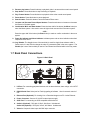
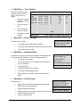
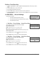
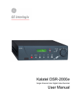
1
Calibur DSR-1000eZ Single Channel Color Digital Video Recorder User Manual WARNING! To prevent fire and electric shock, do not expose this product to rain or moisture. ! The lightning flash with the arrowhead symbol, within an equilateral triangle, is intended to alert the user to the presence of uninsulated "dangerous voltage" within the products enclosure that maybe of sufficient magnitude to constitute a risk of electric shock to persons. The exclamation point, within an equilateral triangle, is intended to alert the user to the presence of important operating and maintenance (servicing) instructions in the literature accompanying the product. CAUTION! To prevent electric shock, do not remove cover. No user serviceable components are inside. Refer servicing to qualified service personnel. CAUTION! Lithium Battery Danger of explosion if battery is incorrectly replaced. Replace only with the same or equivalent type recommended by the manufacturer. ! ATTENTION This product contains a recyclable lithium battery. It may be illegal to dispose of this battery improperly under local, state, or federal laws. Check with your local waste management officials for disposal and recycling options. CAUTION! Electrostatic-Sensitive Device! Use proper CMOS and MOSFET handing precautions, including approved grounded wrists straps, etc., to avoid damage to this unit or its internal components, from electric discharge. WARNING! This equipment generates, uses and can radiate radio frequency energy, and if not installed and used in accordance with the instructions in this manual, may cause interference to radio communications. It has been tested and found to comply with the limits for a Class A computing device pursuant to subpart J of part 15 of FCC rules which are designed to provide reasonable protection against such interference when operated in a commercial environment. This equipment has also been tested and found to comply with the requirements for a CE Class A device and TUV safety standards. Operation of this equipment in a residential area may cause interference, in which case the user is required to take all measures that are necessary, at the user's expense, to correct the interference. Calibur DSR-1000eZ ii 0150-0238A IMPORTANT INFORMATION Software and/or firmware is furnished to the purchaser under a license for use on a single system. Software and/or firmware included with this equipment are the sole proprietary property of, confidential to, and copyrighted by GE Interlogix, Corvallis, Oregon, USA. The software/firmware are not to be copied or disclosed in any manner without the express written consent of GE Interlogix. All information and specifications furnished by GE Interlogix are believed to be accurate and reliable. No responsibility is assumed by GE Interlogix for neither its use nor any infringements of rights of third parties that may result from its use. No license is granted by implication or otherwise under any patent or patent rights of GE Interlogix. The CALIBUR™ brand name and product model numbers are the property of GE Interlogix. COPYRIGHT, 2002: The contents of this manual may not be copied or reproduced in any manner or form without the prior written consent of GE Interlogix. 0150-0238A iii Calibur DSR-1000eZ Calibur DSR-1000eZ iv 0150-0238A CONTENTS 1 FEATURES, CONNECTIONS, AND SETUP ................................................... 1-1 1.1 1.2 1.3 1.4 1.5 1.6 1.7 1.8 1.9 1.10 Product Description.........................................................................................1-1 Features............................................................................................................1-1 Unpacking ........................................................................................................1-1 Installation Environment .................................................................................1-2 Passwords........................................................................................................1-2 Front Panel Controls .......................................................................................1-2 Back Panel Connections .................................................................................1-3 Accessories I/O Port........................................................................................1-5 Setting the Time and Date...............................................................................1-7 Setting the Alarms ...........................................................................................1-9 2 USER OPERATIONS ................................................................................. 2-1 2.1 2.2 2.3 2.4 Recording .........................................................................................................2-1 Playback ...........................................................................................................2-2 The Search Interface........................................................................................2-3 Specifying Search Parameters .......................................................................2-4 3 THE MENU SYSTEM................................................................................. 3-1 4 OPERATOR PROGRAMMING ...................................................................... 4-1 4.1 4.2 4.3 4.4 4.5 4.6 4.7 Main Menu → Time/Date..................................................................................4-1 Main Menu → Alarms.......................................................................................4-2 Main Menu → Timer Settings ..........................................................................4-3 Main Menu → Record Settings .......................................................................4-5 Main Menu → Display Settings .......................................................................4-6 Main Menu → Archive Setup...........................................................................4-8 Main Menu → Advanced Menu .....................................................................4-13 5 INSTALLER PROGRAMMING ...................................................................... 5-1 5.1 5.2 5.3 5.4 5.5 5.6 5.7 5.8 5.9 5.10 Advanced Menu → Disk Overwrite Mode.......................................................5-1 Advanced Menu → Disk Maintenance............................................................5-2 Advanced Menu →Audio Record Setting ......................................................5-3 Advanced Menu → Auto Delete Mode............................................................5-4 Advanced Menu → Communications .............................................................5-4 Advanced Menu → Multiplexer Format ..........................................................5-6 Advanced Menu → Adjust Picture..................................................................5-6 Advanced Menu → Front Panel Lock.............................................................5-7 Advanced Menu → Factory Settings..............................................................5-8 Advanced Menu → Change Password ...........................................................5-8 0150-0238A v Calibur DSR-1000eZ 5.11 Advanced Menu → Firmware Upgrade...........................................................5-9 6 RS-232 REMOTE PROTOCOL .................................................................. 6-1 7 FACTORY DEFAULTS ............................................................................... 7-1 8 TECHNICAL SPECIFICATIONS ................................................................... 8-1 9 WARRANTY AND SERVICE........................................................................ 9-1 9.1 9.2 Factory Service ................................................................................................9-1 Warranty and Return Information...................................................................9-2 Calibur DSR-1000eZ vi 0150-0238A 1 FEATURES, CONNECTIONS, AND SETUP 1.1 Product Description The DSR-1000eZ is a Digital Video Recorder designed to be a direct replacement for a Time Lapse VCR. Digital Video Recording allows the user to have continuous recording on a hard disk, without the need for replacing or rewinding of videotapes. The DSR-1000eZ provides menu based search capabilities for recorded events, as well as access to live or recorded data via the Ethernet (optional). 1.2 Features • Single channel Composite Video Input / Output connection. • Accepts Single Camera input or a Multiplexed input from most popular multiplexers. • Compatible with Color or Monochrome cameras. • Records up to 60 pictures per second (NTSC) or 50 pictures per second (PAL). • Continuous Recording in Disk Overwrite mode. • Video Archiving via the unit's SCSI port. • Access to Live or Recorded video via the Ethernet (Ethernet option only). • Continues Recording while Archiving, or transmitting data via the Ethernet (Ethernet option only). • A simple on-screen menu system. • Includes WaveReader software for viewing Live or Recorded images on a PC (Ethernet option only). • Timed recording. • Audio Recording (Audio option only). • Programmable Auto Delete Mode. 1.3 Unpacking Check the package and contents for visible damage. If any components are missing or damaged, contact the supplier immediately. Do not attempt to use the unit. If, for any reason they must be returned, the contents must be shipped in the original packaging. Package Contents • The DSR-1000eZ unit. • Accessories PCB. • The DSR-1000eZ user manual. • WaveReader software with User Manual (Ethernet option only). • Archiving Addendum. 0150-0238A 1-1 Calibur DSR-1000eZ 1.4 Installation Environment Power: Ensure that the site's AC power is stable and within the rated voltage of the external power supply. If the site's AC power is likely to have spikes or power dips, use power line conditioning or an Uninterruptable Power Supply (UPS). Ventilation: Install the unit in a well-ventilated area. Take note of the locations of the cooling vents in the unit's enclosure, and ensure that they are not obstructed. Temperature: Observe the unit's ambient temperature specifications when choosing a location space. Extremes of heat or cold beyond the specified operating temperature limits may cause the unit to fail. Do not install the unit on top of other hot equipment. Moisture: Do not expose the unit to rain or moisture. Moisture can damage the internal components. Do not install this unit near sources of water. Chassis: You can place other equipment on top of the unit if it weighs less than 35 pounds. 1.5 Passwords Figure 1-1 Passwords Password Name Function Changeable by user? Password Advanced Menu Password Provides access to the Advances menu for the installer. Yes: See page 5-8 3477 Factory Password Restores the unit to the factory defaults. No 8111 A password is provided to limit access to the Advanced menu. It is recommended that the default password be changed after installation is complete. As a security measure, store the password in the administrator's secured files or in a limited access area. For instructions on entering the Advanced menu with the password see section 4.7 Main Menu → Advanced Menu on page 4-13. A password is also provided to return the unit to the factory defaults. For instructions on returning the unit to the factory defaults, see section 5.8 Advanced Menu → Factory Settings on page 5-8. 1.6 Front Panel Controls Figure 1-2 Front Panel 9 1 2 3 4 5 6 7 10 8 1. Record button: Press this button to begin recording. Calibur DSR-1000eZ 1-2 0150-0238A 2. Reverse play button: Press this button to playback video in reverse at the normal record speed. 3. Stop button: Press this button to stop Recording or Playback. 4. Play Forward button: Press this button to playback video at the normal record speed. 5. Pause button: Press this button to pause playback. 6. Search button: Press this button to enter the Search Filters menu. 7. Increase and Decrease Record Speed buttons: Press these buttons to increase or decrease the Record or Playback speed. 8. Combination Menu and Enter button: Press the lower half of the button (the Menu button) to enter the Menu system. Also used to move to higher level menus while in the menu system. --OR— Press the upper half of the button (the Enter button) to make or confirm a selection in the menu system. 9. Power On Indicator and Alarm Indicator: Indicates power and an alarm indication when their respective LED’s are lit. 10. Jog / Shuttle: The Jog (the inner of the two dials) is used for single frame advance while in Pause mode; it is also used to change the value of a parameter while in the menu system. The Shuttle (the outer of the two dials) is used to Fast Forward and Rewind while in the Play mode. 1.7 Back Panel Connections Figure 1-3 Back Panel 1 3 2 4 5 6 7 1. I/O Port: For connecting peripheral devices such as alarm devices, alarm relays, or the VEXT connection. 2. RS-232 Serial Port: Serial port for Flash Upgrading of software. Also for external control of unit. 3. Ethernet Port (Optional): For viewing Live or Recorded images on a PC via the Ethernet. 4. Power Connector: Connect 12 Volt DC external power supply. 5. SCSI Port: For connecting an SCSI compatible archive device. 6. Audio In (Optional): RCA jack, 315mV, 40k Ohms. Unbalanced. Audio Out (Optional): RCA jack, 315mV, 600 Ohms. Unbalanced. 7. Video In: Composite video input with BNC style connector. 0150-0238A 1-3 Calibur DSR-1000eZ Video Out: Composite video output with BNC style connector. Ethernet Port (Ethernet models only) The cable connection configuration depends on your network configuration: • For a DSR-1000eZ that connects directly to a Hub, use a Straight Through connection. • For a DSR-1000eZ that connects directly to a PC, use a Cross Over connection. Wire Type: CAT5 Connector Type: RJ-45 Max Cable Length: 100 feet / 30.5 meters Minimum Cable Length: 6 feet / 1.8 meters Hub Wiring Configuration: Straight Through Consult with your MIS personnel for the specific type of configuration. See section 5.5 Advanced Menu → Communications for information about configuring the ethernet settings in the menu system. PC Wiring Configuration: Cross Over RJ-45 Pin Configuration for Ethernet Port Pin Use Pin Use 1 TX+ 5 Not Connected 2 TX- 6 RX- 3 RX+ 7 Not Connected 4 Not Connected 8 Not Connected 1 2 3 4 5 6 7 8 RJ-45 Connector on Back Panel Power Connector Power Supply Input Power Supply Output Voltage: 120 to 240 Volt AC Voltage: 12 Volt DC Tolerance: ±10% Power: 35 Watt Frequency: 50 to 60 Hz Connector: 2.1mm barrel, Center Positive SCSI Port The unit is equipped with a SCSI port for connecting external archive devices. The unit only supports a single SCSI device. The SCSI ID must be set to 0. Connector: 50 Pin, High Density SCSI-2. The SCSI bus must be terminated, otherwise the system will not operate properly. Autoloader Support?: No Additional menu setup may be necessary to configure archive device. See section 4.6 Main Menu → Archive Setup. Calibur DSR-1000eZ 1-4 Gender (on unit): Female Compatible devices: DAT, AIT, CD-R, CD-RW SCSI ID: 0 0150-0238A RS-232 Serial Port Use a Null Modem cable when connecting to a PC. When connecting to a multiplexer, it may be necessary to construct a cable using the pinout documentation of the MUX as a guide. See the pin-out configuration for the DSR-1000eZ below. Connector Type: DB-9 Gender (on unit): Male Cable Required (Connected to PC): Null Modem Cable Required (Connected to Multiplexer): Variable, depending on pin-out configuration of MUX. DB-9 Pin Configuration for Serial Port Pin Use Pin Use Pin Use 1 DCD 4 Not Connected 7 RTS 2 RX 5 Ground 8 CTS 3 TX 6 Not Connected 9 Not Connected 1 5 6 9 DB-9 Connector on Back Panel Video Input and Output The unit is equipped with a Composite video input and output. The video input is auto terminating. Composite Input: 75 Ohm BNC connector. Composite Output: 75 Ohm BNC connector. Composite Looping: Yes, while unit is On or Off. 1.8 Accessories I/O Port Pin 4: Alarm Record Reset. Pin 9: Disk End Out. Pin 5: VEXT Pulse Out. Pin 10: Ground. 9 Pin 8: Videoloss Out. 5 GND Pin 3: Record Start In. 8 Pin 7: Ground. 4 Pin 2: Alarm Out. DB-9 Connector on Back Panel 3 Pin 6: Error Out. 9 7 Pin 1: Alarm In. 6 6 If the Accessories PCB is lost or missing, contact GE Interlogix Customer Service for a replacement (Part Number 0900-0127a). As a substitute, purchase a female DB-9 connector and make all connections as shown in this section. 5 2 Do not attempt to wire accessories directly to the DB-9 connector. ACCESSORIES 1 1 The back panel of the unit is equipped with an Accessories Port (DB-9 style connector). Connect the Accessories PCB (supplied with the unit) to the Accessories Port. Wire all accessories to the Accessories PCB. Accessories PCB 0150-0238A 1-5 Calibur DSR-1000eZ Alarm In An alarm condition can be activated by an Active Low TTL input or by relay contact devices such as pressure pads, passive infrareds, door switches, or other similar devices. Input: Active Low TTL w/ pull-ups or Normally Open Relay. High: 5V (12V tolerant) Low: Ground Minimum Duration: 0.5 Seconds Figure 1-4 Normally Open Relay Alarm Connection A larm Input Pin 1 Normally Open (Closes During Alarm) Ground Pin 7 or 10 Typical Alarm Device Accessories PCB Refer to each alarm devices's manual for specific wiring details. Alarm Out The Alarm output is activated when a teletext alarm is detected, or while the Alarm Input is active. The Alarm output is only active for the duration of the alarm event. Output: Active Low High: 12V Low: Ground Current Out: 50mA Max Short Circuit Protected. Low for duration of alarm. Record Start In Record Start In will place the unit in Record mode when activated. Compatible with the Disk End Out signal from a second unit. Input: Active Low TTL w/ pull-ups or Normally Open Relay. High: 5V (12V tolerant) Low: Ground Minimum Duration: 0.5 Seconds Alarm Record Reset This feature is for future development, and has not yet been implemented. Calibur DSR-1000eZ 1-6 0150-0238A VEXT Pulse Out The Video External Pulse connection (VEXT) simplifies multiplexer operation by automatically synchronizing the Multiplexer and the DSR-1000eZ. The DSR-1000eZ sends a VEXT pulse to the Multiplexer indicating that it is ready to record the next image. The Multiplexer responds by sending the next image to the Video Input on the DSR-1000eZ. Output: Active Low High: 5V Low: Ground (0.8V Max) Current Out: 50mA Max Short Circuit Protected. The VEXT connection is especially beneficial for units configured with dual record speeds (Normal and Alarm). Use of the VEXT connection is Highly Recommended when connecting the unit to a multiplexer. Error Out The Error Out signal is activated when the unit experiences any operational or internal error. Output: Open Collector High: Transistor Off Low: Transistor On Active When On. Current Out: 10mA Max Minimum Duration: 0.5 Seconds Videoloss Out The Videoloss Out signal is activated when the unit experiences videoloss on the selected video input (Composite or SVHS). In the event of videoloss, VIDEOLOSS will be indicated near the upper left hand corner of the primary monitor. Output: Open Collector High: Transistor Off Low: Transistor On Active When On. Current Out: 10mA Max Minimum Duration: 0.5 Seconds Disk End Out The Disk End Out is activated when there is 5 minutes of recording space left on the hard disk. It will also be activated if a DAT or AIT tape archiving device is connected, and the tape end is encountered. The DSR-1000eZ must be in Record mode, with Background Archiving ON, and set to Continuous Overwrite mode. Output: Open Collector High: Transistor Off Low: Transistor On Active When On. Current Out: 10mA Max Minimum Duration: 0.5 Seconds 1.9 Setting the Time and Date It is recommended that, as a minimum, the following menu items be configured before using the unit. For detailed information about using the menu system, see section 3. 0150-0238A 1-7 Calibur DSR-1000eZ o Main Menu → Time/Date → Set Time Format To set the Time format, use the Jog to select the desired Time format. Format the time as either: • 12 HOUR • 24 HOUR Time Format Setup Select Format 12 Hour Press the Enter button to confirm the selection and exit the menu. --OR— Press the Menu button to exit the menu without making changes. o Main Menu → Time/Date → Set Date Format To set the Date format, use the Jog to select the desired Date format. Format the Date as either: • DD/MM/YY • MM/DD/YY • YY/MM/DD Date Format Setup Select Format MM/DD/YY Press the Enter button to confirm the selection and exit the menu. --OR— Press the Menu button to exit the menu without making changes. o Main Menu → Time/Date → Set Time Time Setup To set the Time: 1. With HH MM SS highlighted, press the Enter button. The highlighting will move to the row of numbers. 2. Enter the time in Hours, Minutes, and Seconds. Use the Jog to change the values. Use the Shuttle to navigate among the three fields. HH MM SS 03 05 53 [CANCEL] [OK] 3. Press the Enter button to confirm the selection. 4. To Save the changes and Exit the menu: Use the Jog to select [OK], then press the Enter button. --OR-5. To Exit the menu without making changes: Use the Jog to select [CANCEL], then press the Enter button. Calibur DSR-1000eZ 1-8 0150-0238A o Main Menu → Time/Date → Set Date Date Setup To set the Date: 1. With MM DD YY DAY highlighted, press the Enter button. The highlighting will move to the row of numbers. 2. Enter the date in Months, Days, Years. Day of the Week will update automatically. Use the Jog to change the values. Use the Shuttle to navigate among the three fields. MM DD YY DAY 12 17 00 SUN [CANCEL] [OK] 3. Press the Enter button to confirm the selection. 4. To Save the changes and Exit the menu: Use the Jog to select [OK], then press the Enter button. --OR-5. To Exit the menu without making changes: Use the Jog to select [CANCEL], then press the Enter button. 1.10 Setting the Alarms o Main Menu → Alarms Alarms Menu Use this menu to specify: • Whether an alarm condition will be activated when the unit detects a signal on the Alarm In connection. • Whether a teletext alarm signal (generated by a multiplexer or other device) will cause the unit to activate an alarm condition. • Whether the internal buzzer is activated during an alarm condition. To configure the alarm settings: Hardwire Alarm Teletext Alarm Alarm Buzzer [CANCEL] : Enable : Disable : Enable [OK] Alarms Menu 1. Use the Shuttle to navigate among the fields. 2. Use the Jog to change the values of the highlighted fields. 3. To Save the changes and Exit the menu: Use the Jog to select [OK], then press the Enter button. Hardwire Alarm Teletext Alarm Alarm Buzzer [CANCEL] : Enable : Disable : Enable [OK] --OR-4. To Exit the menu without making changes: Use the Jog to select [CANCEL], then press the Enter button. 0150-0238A 1-9 Calibur DSR-1000eZ Calibur DSR-1000eZ 1-10 0150-0238A 2 USER OPERATIONS 2.1 Recording To begin recording, press the Record button. RECORD will be indicated for three seconds, near the upper left hand corner of the primary monitor. The unit always starts recording at the end of the previously recorded data. RECORD Recording will continue until: • Another mode is selected (Play mode, Reverse Play,or Stop mode). • The disk is full (In No Overwrite and Overwrite Once modes). See section 5.1 Advanced Menu → Disk Overwrite Mode on page 5-1, for details regarding Disk Overwrite modes. Record button Normal Recording The unit records at the normal record speed until an alarm condition is detected. The normal record speed is indicated on the monitor if the display option is enabled, and can be altered using the Up/Down Record Speed buttons, or in the menu system. For information about altering the normal record speed from the menu system, see Main Menu → Record Settings → Normal Record Speed, on page 4-5 of the Operator Programming section of this manual. The normal record speed can be altered while the unit is recording. The unit will continue recording while the menu system is active. REC/PLAY SPEED Record Speed buttons Alarm Recording When an alarm condition is detected, the unit automatically switches to the alarm record speed. The alarm condition is indicated in several ways: • With the word ALARM, displayed on the primary monitor, near the upper left hand corner of the screen. • With the internal buzzer (if activated in the menu system). For information about activating the internal buzzer during alarms, see Main Menu → Alarms on page 4-2 of the Operator programming section of this manual. • By an external device, connected to the alarm output of the unit (if the unit is installed that way). ALARM Alarm Indicator The alarm record speed cannot be changed using the Up/Down Record Speed buttons on the front panel. The alarm record speed must be changed in the menu system. For information about altering the alarm record speed, see Main Menu → Record Settings → Alarm Record Speed, on page 4-5 of the Operator Programming section of this manual. The unit returns to the normal record speed when the alarm condition ends. 0150-0238A 2-1 Calibur DSR-1000eZ Disk Nearly Full Notification This message will appear on the primary monitor to indicate that the unit has stopped recording, because the disk is full. Message Disk Full. Recording Has Stopped. In No Overwrite mode: The user must acknowledge the on-screen message by pressing the Enter button. [OK] Unit will not record over previously recorded data. To continue recording, the data must be erased (or deleted) in the Advanced → Disk Maintenance menu. In Overwrite Once mode: The user must acknowledge the on-screen message by pressing the Enter button. The unit will continue recording again when the user presses the Record button. 2.2 Playback Play Forward To begin normal playback, press the Play Forward button. The unit will begin playing back data from the beginning of the last recording session. PLAY Playback is indicated: • As PLAY near the upper left hand corner of the primary monitor, for three seconds. Play Forward button Reverse Play To begin reverse playback, press the Reverse play button. The unit will begin playing back data from the beginning of the last recording session. REVERSE PLAY Reverse playback is indicated: • As REVERSE PLAY near the upper left hand corner of the primary monitor, for three seconds. If there is only one recording session on the hard disk, the unit will indicate START OF DATA on the primary monitor. Reverse play button Playback Speed The unit will playback the data at the rate it was recorded. The user can alter the playback speed using the Up/Down Record Speed buttons. Altering the playback speed overrides any change in playback speed that would occur due to an alarm condition in the playback. To clear the override, press the Stop button, then press the Play button to resume playback at the speed the data was recorded. Calibur DSR-1000eZ 2-2 REC/PLAY SPEED Record Speed buttons 0150-0238A Fast Forward During playback, rotate the Shuttle clockwise to view the data at a Higher than normal rate. Increasing the amount of rotation increases the rate of playback. REW FF Fast Forward is indicated: • As FAST FORWARD near the upper left hand corner of the primary monitor, for three seconds. Jog / Shuttle Rewind During playback, rotate the Shuttle counter-clockwise to view the data (in reverse) at a Higher than normal rate. Increasing the amount of rotation increases the rate of playback. REW FF Rewind is indicated: • As REWIND near the upper left hand corner of the primary monitor, for three seconds. Jog / Shuttle Pause PAUSE During playback, press the Pause button to pause playback, and display a single frame on-screen. Pause is indicated: • As PAUSE near the upper left hand corner of the primary monitor, for three seconds. Pause button Single Frame Advance & Single Frame Rewind During Pause mode, rotate the Jog dial to view the frame directly before or after the frame displayed on-screen. REW FF Jog / Shuttle Start of Data & End of Data If the start or end of data is reached during playback, START OF DATA or END OF DATA is indicated near the upper left hand corner of the primary monitor. 2.3 The Search Interface The Search Interface feature allows the user to search the hard disk for recorded events, such as an alarm condition, or a previous recording session. For example, each time Record mode is activated, it is considered a separate recording session. To enter the Search Filters menu, press the Search button. The Search Filters menu is displayed on the primary monitor. 0150-0238A 2-3 SEARCH Search button Calibur DSR-1000eZ Search Filters Use this to specify: • • The Start and Stop date of the search. The Start and Stop time of the search. • Which cameras to search exclusively. • To search for recorded alarms. Start DATE: 12/25/00 (MM/DD/YY) Start TIME: 11:11:21 [ ] [ ] Stop 01/01/01 (MM/DD/YY) Stop 12:34:34 [ ] [ ] 1 2 3 4 5 6 7 8 CAMERA: [ ][ ][ ][ ][ ][ ][ ][ ] ALARM: [ ] [CANCEL] [START SEARCH] Searching for All Recorded Events Using the Shuttle to navigate, highlight [START SEARCH], then press the Enter button. The Search Results window will appear. For information about selecting a recorded event, see Selecting from the Search Results, in this section. 2.4 Specifying Search Parameters Selecting a Start and Stop Date 1. Using the Shuttle to navigate, highlight the DATE parameter, then press the Enter button. The unit will enter Edit mode. 2. Use the Jog to change the start and stop date values. Use the Shuttle to navigate among the different parameters. 3. To activate the start or stop date parameter, use the Jog to place an [X] in the check box. 4. Press the Enter button at any time to exit Edit mode. Selecting a Start and Stop Time 1. Using the Shuttle to navigate, highlight the TIME parameter, then press the Enter button. The unit will enter Edit mode. 2. Use the Jog to change the start and stop time values. Use the Shuttle to navigate among the different parameters. 3. To activate the start or stop time parameter, use the Jog to place an [X] in the check box. 4. Press the Enter button at any time to exit Edit mode. Selecting Cameras to Search 1. Using the Shuttle to navigate, highlight the CAMERA parameter, then press the Enter button. The unit will enter Edit mode. 2. Use the Shuttle to navigate among the different cameras. 3. Use the Jog to select a camera (or cameras) by placing an [X] in the check box. 4. Press the Enter button at any time to exit Edit mode. Calibur DSR-1000eZ 2-4 0150-0238A Searching for Recorded Alarms 1. Using the Shuttle to navigate, highlight the ALARM parameter, then press the Enter button. The unit will enter Edit mode. 2. Use the Jog to activate the alarms search, by placing an [X] in the check box. 3. Press the Enter button at any time to exit Edit mode. Starting the Search Using the Shuttle to navigate, highlight the [START SEARCH] parameter, then press the Enter button. The Search Results menu will appear. Search Results 9 Start Date Start Time Days HH MM SS 000 01/21/2002 20:07:10 0 04:35:15 001 01/21/2002 20:08:10 0 00:01:55 002 01/21/2002 20:09:10 0 00:00:38 003 01/21/2002 20:10:10 0 01:07:22 004 01/22/2002 20:07:10 0 00:00:07 005 01/23/2002 20:07:10 0 00:08:56 006 01/24/2002 20:07:10 0 00:00:06 007 01/25/2002 20:07:10 0 05:57:31 008 01/26/2002 20:07:10 0 00:46:43 matches found. ‘ENTER’ to play event. Selecting from the Search Results Use the Shuttle to select a recorded event. Press the Enter button to select the event, or press the Menu button to exit the Search Results menu. 0150-0238A 2-5 Calibur DSR-1000eZ 3 THE MENU SYSTEM This section provides a brief overview of the menu system, for complete information about Operator and Installer programming, see section 4: Operator Programming, or section 5: Installer Programming. How to use this Manual Throughout this manual, there are headings like these. o Main Menu → Timer Settings Meaning: From the Main menu, select TIMER SETTINGS, then press the Enter button. A Pop-up or Pull down menu will appear. o Main Menu → Record Settings → Normal Record Speed Meaning: From the Main menu, select RECORD SETTINGS, then press the Enter button. This opens another menu. In this menu, select NORMAL RECORD SPEED, then press the Enter button. A Pop-up or Pull down menu will appear. Pull-down Menus Pull-down menus are the top-level menus. Make a selection in a Pull-down menu to enter the appropriate sub-menu (typically a Pop-up menu). Changes to the unit's parameters are usually made in Pop-up menus. To exit a Pull-down menu, press the Menu button. Pop-up Menus Pop-up menus usually have a parameter (or several parameters), from which the user can make a selection or change the value. Use the Shuttle to select a new parameter, use the Jog to change the value of that parameter. To Save changes and Exit the menu: Select [OK], the press the Enter button. To Exit the menu without making changes: Press the Menu button or select [CANCEL], then press the Enter button. ENTER MENU Menu button In some boxes, items are highlighted on the screen. They are represented in this manual as follows: 0150-0238A Not highlighted: Highlighted: TIME/DATE ALARMS 3-1 Calibur DSR-1000eZ Entering the Main menu Enter the Main menu by pressing the Menu button. The Main menu will appear on the primary monitor. ENTER MENU Menu button The Main Menu The Main menu provides access to all of the operator programmable options. Each sub-section of the Main menu is described briefly in this section. For complete information about operator programming in the Main menu, see section 4. Time/Date Alarms Timer Settings Record Settings Display Settings Archive Setup Advanced Menu About DSR-1000eZ o Main Menu → Time/Date Use this menu to specify: o • The time format: 12 or 24 hours. • The date format: MM/DD/YY, DD/MM/YY, or YY/MM/DD. • The time. • The date. Set Set Set Set Time Format Date Format Time Date Main Menu → Alarms Alarms Menu Use this menu to specify: • Whether an alarm condition will be activated when the unit detects a signal on the Alarm In connection. • Whether a teletext alarm signal (generated by a multiplexer or other device) will cause the unit to activate an alarm condition. • Whether the internal buzzer is activated during an alarm condition. Calibur DSR-1000eZ 3-2 Hardwire Alarm Teletext Alarm Alarm Buzzer [CANCEL] : Enable : Disable : Enable [OK] 0150-0238A o Main Menu → Timer Settings This menu allows the user to program a timed-recorded event. Use this menu to specify: o • The date, or days on which the recording will occur. • The start and stop time. • The record speed. • The record quality. • Whether the event is enabled. DAY START STOP SPD(pps) QUALITY ON/OFF 31 SAT MON-FRI SAT-SUN MON-SUN -- 16:45 07:55 09:56 14:23 02:23 --:-- 17:05 08:10 11:05 14:50 03:34 --:-- 20 10 60 60 20 -- High Med Low High Med -- On Off On On Off -- [OK] EDIT Mode Hit "ENTER" To Toggle EDIT Mode Main Menu → Record Settings Use this menu to specify: o • The record speed during Normal recording. • The record speed when the unit detects an alarm condition. • The recorded picture quality. Main Menu → Display Settings Use this menu to specify what status information will be displayed on the primary monitor. Select On or Off, for the following items. o Normal Record Speed Alarm Record Speed Video Quality Current Time / Date Record Capacity Archive Status Last Alarm • The current time and date. • The remaining amount of time before the hard disk runs out of record space. Record/Playback Speed • The Archive Status. Playback Time / Date • The time and date of the last alarm. • The current record/playback speed. • During Playback, the time and date the recording was made. Main Menu → Archive Setup Use this menu to: • Select data to be archived and begin archiving process. • Restore data from archive device. • Enable background archiving. • Specify how the unit will handle overwrite issues when the archive medium becomes full. • Erase the archived data. 0150-0238A Selective archive Restore from archive Background archive Archive Overwrite Mode 3-3 Erase Archive Medium Calibur DSR-1000eZ Main Menu → Advanced Menu Password Box To access the Advanced menu: 1. Select ADVANCED MENU from the Main menu, then press the Enter button. The Password Box will appear. Please Enter The Password! 0--- 2. Enter the Advanced menu password. Use the Jog to select a character, then use the Enter button to complete the selection, and move to the next character. 3. Pressing the Enter button on the last character will complete the password selection and the unit will display the Advanced menu. o Main Menu → About DSR-1000eZ Use this menu to display information about the DSR-1000eZ. Select Main Menu → About DSR1000eZ to display the About DSR-1000eZ screen. Serial Number: Software Version: Software Date: Software Checksum: Boot Code Ver.: Disk Size: D406-T72F-219019 2.00 Sep 03 2002 16:40:18 41173C6B 1.00 161.99 GB Ethernet Enable: Ethernet Address: Hardware Address: Enabled 10.90.253.10 BA-BE-C6-7E-FA-CE Ethernet information will not be displayed unless the DSR1000eZ is an ethernet supplied model. [OK] The Advanced Menu For security reasons, a password is provided to limit access to the Advanced menu. For instructions about entering the Advanced menu, see Main Menu → Advanced Menu, on the previous page. The Advanced menu provides access to all of the installer programmable options. Each sub-section of the Advanced menu is described briefly in this section. For complete information about installer programming in the Advanced menu, see section 5. Disk Overwrite Mode Disk Maintenance Audio Record Setting Auto Delete Mode Communications Multiplexer Format Adjust Picture Front Panel Lock Factory Settings Change Password Firmware Upgrade Calibur DSR-1000eZ 3-4 0150-0238A o Advanced Menu → Disk Overwrite Mode Use this menu to specify how the unit will handle disk overwrite issues once the hard disk becomes full. Select either: o Disk Overwrite Mode Select Mode • No Overwrite. • Overwrite Once. • Continuous Overwrite. Continuous Overwrite Advanced Menu → Disk Maintenance Delete Undelete Erase The user can have previously recorded information: • Deleted (with the possibility of restoring it). • Undeleted (restored if it has not yet been overwritten). • Erased (removed with no possibility of restoring it). Selecting erase will display the following warning box. Erase Disk All data will be permanently erased! Do You want to continue? [CANCEL] o [OK] Advanced Menu → Audio Record Setting (Audio equipped model only) Use this menu to: • Select Off and Disable the audio recording capability. • Select G.711 and Enable the audio recording capability. This selection will be grayed out if the DSR-1000eZ is not equipped with the audio option. o OFF G.711 (64kb/s) Advanced Menu → Auto Delete Mode Use this menu to program the Auto Delete Mode. The options available are from 7 to 99 days and Off. 30 days is the default setting. 0150-0238A 3-5 Calibur DSR-1000eZ ADM Setting Message ADM will change. Are you sure? 30 Days Yes o Advanced Menu → Communications Use thus menu to specify: • The data transfer rate for the RS-232 serial port. • The units Ethernet network connection settings (Ethernet option only). Baud Rate Ethernet Settings Modem Settings • The Modem connection settings. o Advanced Menu → Multiplexer Format The DSR-1000eZ is compatible with several different brands of multiplexers. Use this menu to specify the Playback format of the multiplexer. If the unit is not connected to a multiplexer, select NONE. Note: The DSR-1000eZ can auto detect the camera type connected (NTSC or PAL). The Navco multiplexer is only available on NTSC units. Certain menu items may be grayed out and unavailable under certain circumstances. The Vista VLM is grayed on the menu to the right because the DSR-1000eZ has auto detected that an NTSC input signal is attached. None Kalatel Robot DM Philips Pelco Sanyo Philips REO Navco ATV ATV QSP Vista VLM QSI 1700 Diebold o Advanced Menu → Adjust Picture Use this menu to specify the Brightness, Contrast, and Saturation of the video input. Adjustments made to the video input will alter the recorded image. Calibur DSR-1000eZ 3-6 Brightness Contrast Saturation 0150-0238A o Advanced Menu → Front Panel Lock Use this menu to Lock or Unlock the front panel. o Unlock Keyboard Lock Keyboard Advanced Menu → Factory Settings Use this menu to enter the Factory Password, and restore the unit to the factory defaults. Password Box Please enter the Factory Password O--- o Advanced Menu → Change Password Use this menu to change the Advanced Menu Password. Password Box Enter a new Password O--- 0150-0238A 3-7 Calibur DSR-1000eZ 4 OPERATOR PROGRAMMING 4.1 Main Menu → Time/Date Use this menu to specify: o • The time format: 12 or 24 hours. • The date format: MM/DD/YY, DD/MM/YY, or YY/MM/DD. • The time. • The date. Set Set Set Set Time Format Date Format Time Date Main Menu → Time/Date → Set Time Format To set the Time format, use the Jog to select the desired Time format. Format the time as either: • 12 HOUR • 24 HOUR Time Format Setup Select Format 12 HOUR Press the Enter button to confirm the selection and exit the menu. --OR— Press the Menu button to exit the menu without making changes. o Main Menu → Time/Date → Set Date Format To set the Date format, use the Jog to select the desired Date format. Format the Date as either: • DD/MM/YY • MM/DD/YY • YY/MM/DD Date Format Setup Select Format MM/DD/YY Press the Enter button to confirm the selection and exit the menu. --OR— Press the Menu button to exit the menu without making changes. 0150-0238A 4-1 Calibur DSR-1000eZ o Main Menu → Time/Date → Set Time Time Setup To set the Time: 1. With HH MM SS highlighted, press the Enter button. The highlighting will move to the row of numbers. HH MM SS 03 05 53 2. Enter the time in Hours, Minutes, and Seconds. Use the Jog to change the values. Use the Shuttle to navigate among the three fields. [CANCEL] [OK] 3. Press the Enter button to confirm the selection. 4. To Save the changes and Exit the menu: Use the Jog to select [OK], then press the Enter button. --OR-5. To Exit the menu without making changes: Use the Jog to select [CANCEL], then press the Enter button. o Main Menu → Time/Date → Set Date Date Setup To set the Date: 1. Press the Enter button. The highlighting will move to the row of numbers. 2. Enter the date in Months, Days, Years. Day of the Week will update automatically. Use the Jog to change the values. Use the Shuttle to navigate among the three fields. MM DD YY DAY 12 17 00 SUN [CANCEL] [OK] 3. Press the Enter button to confirm the selection. 4. To Save the changes and Exit the menu: Use the Jog to select [OK], then press the Enter button. --OR-5. To Exit the menu without making changes: Use the Jog to select [CANCEL], then press the Enter button. 4.2 Main Menu → Alarms Alarms Menu Use this menu to specify: • Whether an alarm condition will be activated when the unit detects a signal on the Alarm In connection. • Whether a teletext alarm signal (generated by a multiplexer or other device) will cause the unit to activate an alarm condition. • Whether the internal buzzer is activated during an alarm condition. Hardwire Alarm Teletext Alarm Alarm Buzzer [CANCEL] : Enable : Disable : Enable [OK] A feature unique to the DSR-1000eZ is its ability to detect alarms via teletext provided within the video signal. Standard Time Lapse VCRs can only detect an alarm if the alarm output signal of the Mux is wired directly to the alarm input of the VCR using the VEXT connection. Calibur DSR-1000eZ 4-2 0150-0238A This teletext alarm detecting feature of the DSR-1000eZ is compatible with the following styles of Multiplexers: • • • • Kalatel Philips Robot Pelco • • • • Sanyo Philips REO ATV ATV QSP • • • Vista VLM QSI 1700 Diebold Connecting to Dedicated Micros (DM) When connecting to a Dedicated Micros multiplexer: • It is necessary to connect the alarm output of the Mux to the alarm input of the DSR-1000eZ (as you would do when connecting the alarm input on standard time-lapse VCR). • It is necessary to configure the Main Menu → Alarms → Hardwire Alarm as Enabled. • It is necessary to configure the Main Menu → Alarms → Teletext Alarm as Disable. To configure the alarm settings: Alarm Menu 1. Use the Shuttle to navigate among the fields. 2. Use the Jog to change the values of the highlighted fields. 3. To Save the changes and Exit the menu: Use the Jog to select [OK], then press the Enter button. Hardwire Alarm Teletext Alarm Alarm Buzzer [CANCEL] : Enable : Disable : Enable [OK] --OR-4. To Exit the menu without making changes: Use the Jog to select [CANCEL], then press the Enter button. 4.3 Main Menu → Timer Settings This menu allows the user to program a timed-recorded event. Use this menu to specify: • The date, or days on which the recording will occur. • The start and stop time. • The record speed. • The record quality. • Whether the event is enabled. 0150-0238A DATE START STOP SPD(pps) QUALITY ON/OFF 31 Sat Mon-Fri Sat-Sun Mon-Sun -- 16:45 07:55 09:56 14:23 02:23 --:-- 17:05 08:10 11:05 14:50 03:34 --:-- 20 10 60 60 20 -- High Med Low High Med -- On Off On On Off -- [OK] EDIT Mode 4-3 Hit "ENTER" To Toggle EDIT Mode Calibur DSR-1000eZ Creating a Timed Recording: 1. Using the Jog / Shuttle to navigate, highlight the DATE parameter of the last line item (indicated with double dash marks). 2. Press the Enter button to enter the Edit mode. EDIT MODE will appear on-screen, in the lower left-hand corner of the Timer Settings menu. The user may press the Enter button to exit Edit mode at any time. 3. Use the Jog to change the values of the DATE setting. Date (Day of the Month) 1 through 31 Day of the Week Monday through Sunday Range of Days All Weekdays (Monday-Friday), All Weekend Days (Saturday-Sunday), Monday-Sunday (Everyday) 4. When finished entering the Date, use the Shuttle to navigate the START setting. 5. Use the Jog / Shuttle to enter the time the recording will begin. The Hours and Minutes are edited separately. The start and stop times are always configured in a 24-hour clock. When finished entering the start time, use the Shuttle to navigate to the STOP setting. 6. Use the Jog / Shuttle to enter the time the recording will end. Entering a time "before" the start time will cause the unit to record until the indicated stop time on the next day. When finished entering the stop time, use the Shuttle to navigate to the SPD setting. 7. Use the Jog to enter the record speed in pictures per second. NTSC Record Speeds 60, 30, 20, 10, 5, 3, 2, 1, 0.5, 0.2, 0.1, 0.0 PAL Record Speeds 50, 25, 17, 10, 5, 3, 2, 1, 0.5, 0.2, 0.1, 0.0 8. When finished entering the Record Speed, use the Shuttle to navigate to the QUALITY setting. 9. Use the Jog to enter the record quality (Low, Medium, or High). Higher record quality settings use more disk space. 10. When finished entering the Record Quality, use the Shuttle to navigate to the ON/OFF setting. 11. Use the Jog to Activate, Deactivate, or Delete the recording. 12. When finished, press the Enter button to exit the Edit mode. Use the Jog / Shuttle to navigate to [OK], then press the Enter button to complete the selection. Editing a Timed Recording: 1. Using the Jog / Shuttle to navigate, highlight the event parameter you wish to edit. 2. Press the Enter button to enter the Edit mode. EDIT MODE will appear on-screen, in the lower left-hand corner of the pop-up menu. 3. Use the Jog to change the values. Use the Shuttle to navigate among parameters in the same row. 4. When finished, press the Enter button to exit the Edit mode. Use the Jog / Shuttle to navigate to [OK], then press the Enter button to complete the selection. Calibur DSR-1000eZ 4-4 0150-0238A Deleting a Timed Recording: 1. Using the Jog / Shuttle to navigate, highlight the ON/OFF parameter of the event you wish to delete. 2. Press the Enter button to enter the Edit mode. 3. Use the Jog to select DEL from the menu. 4. Press the Enter button to confirm the selection and exit the Edit mode. 5. Use the Jog / Shuttle to navigate to [OK], then press the Enter button to remove the selection and exit the menu. 4.4 Main Menu → Record Settings Use this menu to specify: o • The record speed during Normal recording. • The record speed when the unit detects an alarm condition. • The recorded picture quality. Normal Record Speed Alarm Record Speed Video Quality Main Menu → Record Settings → Normal Record Speed Use the Jog to select the desired Normal Record Speed. Normal Record Speed Normal Record Speeds: Pictures Per Second NTSC: 60, 30, 20, 10, 5, 3, 2, 1, 0.5, 0.2, 0.1, 0.0. 5 PAL: 50, 25, 17, 10, 5, 3, 2, 1, 0.5, 0.2, 0.1, 0.0. When the Normal Record Speed is set to 0.0, the unit will only record while an alarm is active. Press the Enter button to confirm the selection and exit the menu. --OR— Press the Menu button to exit the menu without making changes. o Main Menu → Record Settings → Alarm Record Speed Use the Jog to select the desired Alarm Record Speed. Alarm Record Speeds: Alarm Record Speed Pictures Per Second NTSC: 60, 30, 20, 10, 5, 3, 2, 1, 0.5, 0.2, 0.1. 60 PAL: 50, 25, 17, 10, 5, 3, 2, 1, 0.5, 0.2, 0.1. Press the Enter button to confirm the selection and exit the menu. --OR— Press the Menu button to exit the menu without making changes. 0150-0238A 4-5 Calibur DSR-1000eZ o Main Menu → Record Settings → Video Quality Use the Jog to select the desired Record Quality. Select High, Med or Low. Record Quality Higher record quality’s use lower compression, requiring more disk space. Select Quality Press the Enter button to confirm the selection and exit the menu. High --OR— Press the Menu button to exit the menu without making changes. 4.5 Main Menu → Display Settings Use this menu to specify what status information will be displayed on the primary monitor. Select On or Off, for the following items. o • The current time and date. • The remaining amount of time before the hard disk runs out of record space. • The Archive Status. • The time and date of the last alarm. • During Playback, the time and date the recording was made. Current Time / Date Record Capacity Archive Status Last Alarm Playback Time / Date Main Menu → Display Settings → Current Time / Date To display the current Time and Date near the upper right hand corner of the primary monitor, select ON. Use the Jog to select On or Off. OFF ON Press the Enter button to confirm the selection and exit the menu. --OR— Press the Menu button to exit the menu without making changes. Calibur DSR-1000eZ 4-6 0150-0238A o Main Menu → Display Settings → Record Capacity Select ON, to display the amount of time remaining before the hard disk runs out of record space. The data is displayed near the upper left hand corner of the primary monitor. The unit displays the Record Capacity with two measures of time, and switches automatically depending on the amount of time remaining: • Days and Hours • Hours and Minutes • Minutes and Seconds OFF ON Use the Jog to select ON or OFF. Press the Enter button to confirm the selection and exit the menu. --OR— Press the Menu button to exit the menu without making changes. o Main Menu → Display Settings → Archive Status To display the archive status near the upper center of the screen on the primary monitor, select ON. The unit will display either: • ARCHIVE NOT CONNECTED. • ARCHIVE READY. • ARCHIVE NOT READY. OFF ON Use the Jog to select ON or OFF. Press the Enter button to confirm the selection and exit the menu. --OR— Press the Menu button to exit the menu without making changes. o Main Menu → Display Settings → Last Alarm To display the time and date of the last alarm, near the upper right hand corner of the primary monitor, select On. The unit will display NONE if there is no previous record of an alarm. OFF ON Use the Jog to select On or Off. Press the Enter button to confirm the selection and exit the menu. --OR— Press the Menu button to exit the menu without making changes. o Main Menu → Display Settings → Playback Time / Date To display the time and date the recording was made (during playback) select On. The data is displayed near the upper right hand corner of the screen. OFF ON Use the Jog to select On or Off. Press the Enter button to confirm the selection and exit the menu. --OR— Press the Menu button to exit the menu without making changes. 0150-0238A 4-7 Calibur DSR-1000eZ o Main Menu → Display Settings → Record/Playback Speed OFF ON To display the Record/Playback Speed, near the upper right hand corner of the primary monitor, select On. Use the Jog to select On or Off. Press the Enter button to confirm the selection and exit the menu. --OR— Press the Menu button to exit the menu without making changes. 4.6 Main Menu → Archive Setup Selective archive Restore from archive Background archive Use this menu to: o • Select data to be archived and begin archiving process. • Restore data from archive device. • Enable background archiving. • Specify how the unit will handle overwrite issues when the archive medium becomes full. • Erase the archived data. Archive Overwrite Mode Erase Archive Medium Main Menu → Archive Setup → Selective Archive The Selective Archive feature allows the user to archive recorded data from the hard disk onto a CD, DAT, AIT, RAID, or DVSe. See the Archiving Addendum for details about using archive devices. The Archive Search Filters menu allows the user to search the hard disk for recorded events, such as an alarm condition, or a previous recording session, then select events to be archived for later viewing. For example, each time Record mode is activated, it is considered a separate recording session. Archive Search Filters Use this menu to specify: • The Start and Stop date of the search. • The Start and Stop time of the search. • Which cameras to search exclusively. • To search for recorded alarms. Start DATE: 12/25/00 (MM/DD/YY) Start TIME: 11:11:21 [ ] [ ] Stop 01/01/01 (MM/DD/YY) Stop 12:34:34 [ ] [ ] 1 2 3 4 5 6 7 8 CAMERA: [ ][ ][ ][ ][ ][ ][ ][ ] ALARM: [ ] [CANCEL] [START SEARCH] Searching for All Recorded Events Using the Shuttle to navigate, highlight [START SEARCH], then press the Enter button. The Archive Search Results window will appear. For information about selecting a recorded event, see Selecting from the Archive Search Results, in this section. Calibur DSR-1000eZ 4-8 0150-0238A Specifying Search Parameters Selecting a Start and Stop Date 1. Using the Shuttle to navigate, highlight the DATE parameter, then press the Enter button. The unit will enter Edit mode. 2. Use the Jog to change the start and stop date values. Use the Shuttle to navigate among the different parameters. 3. To activate the start or stop date parameter, use the Jog to place an [X] in the check box. 4. Press the Enter button at any time to exit Edit mode. Selecting a Start and Stop Time 1. Using the Shuttle to navigate, highlight the TIME parameter, then press the Enter button. The unit will enter Edit mode. 2. Use the Jog to change the start and stop time values. Use the Shuttle to navigate among the different parameters. 3. To activate the start or stop time parameter, use the Jog to place an [X] in the check box. 4. Press the Enter button at any time to exit Edit mode. Selecting Cameras to Search 1. Using the Shuttle to navigate, highlight the CAMERA parameter, then press the Enter button. The unit will enter Edit mode. 2. Use the Shuttle to navigate among the different cameras. 3. Use the Jog to select a camera (or cameras) by placing an [X] in the check box. 4. Press the Enter button at any time to exit Edit mode. Searching for Recorded Alarms 1. Using the Shuttle to navigate, highlight the ALARM parameter, then press the Enter button. The unit will enter Edit mode. 2. Use the Jog to activate the alarms search, by placing an [X] in the check box. 3. Press the Enter button at any time to exit Edit mode. 0150-0238A 4-9 Calibur DSR-1000eZ Starting the Search Using the Shuttle to navigate, highlight the [START SEARCH] parameter, then press the Enter button. The Archive Search Results menu will appear. Archive Search Results 000 001 002 003 Start Date 11/28/2000 11/29/2000 11/29/2000 11/29/2000 Start Time 17:52:14 09:35:20 10:00:04 10:03:25 Size (MB) 26842 [ ] 2062 [ ] 278 [x] 66 [x] Selected [ 383 ](MB) Available on Target Medium [ 652 ](MB) “ENTER” to play “SEARCH” to archive Selecting from the Archive Search Results 1. Use the Jog to navigate, highlighting the recorded event you wish to select 2. Use the Shuttle to select a recorded event by placing an [x] in the check box. Starting the Archive Process To begin archiving, press the Search button. The Archiving progress bar will appear. Press the Enter button to cancel archiving at any time. Archiving… [CANCEL] When the unit is finished archiving this message box will appear. Press the Enter button to acknowledge the message and complete the archiving process. Message Archiving completed. [OK] o Main Menu → Archive Setup → Restore From Archive The DSR-1000eZ supports data restoration to the hard disk from an archive device. Data may be restored from a DAT, AIT, RAID, or DVSe. See the Archiving Addendum for details about using archive devices. The DSR-1000eZ does allow the user to search the archived data for recorded events, such as an alarm condition, or a previous recording session. Calibur DSR-1000eZ 4-10 0150-0238A Restore Search Filters Use this to specify: • • The Start and Stop date of the search. The Start and Stop time of the search. • Which cameras to search exclusively. • To search for recorded alarms. Start DATE: 12/25/00 (MM/DD/YY) Start TIME: 11:11:21 [ ] [ ] Stop 01/01/01 (MM/DD/YY) Stop 12:34:34 [ ] [ ] 1 2 3 4 5 6 7 8 CAMERA: [ ][ ][ ][ ][ ][ ][ ][ ] ALARM: [ ] [CANCEL] [START SEARCH] Searching for All Recorded Events Using the Shuttle to navigate, highlight [START SEARCH], then press the Enter button. The Restore Search Results window will appear. Specifying Search Parameters Selecting a Start and Stop Date 1. Using the Shuttle to navigate, highlight the DATE parameter, then press the Enter button. The unit will enter Edit mode. 2. Use the Jog to change the start and stop date values. Use the Shuttle to navigate among the different parameters. 3. To activate the start or stop date parameter, use the Jog to place an [X] in the check box. 4. Press the Enter button at any time to exit Edit mode. Selecting a Start and Stop Time 1. Using the Shuttle to navigate, highlight the TIME parameter, then press the Enter button. The unit will enter Edit mode. 2. Use the Jog to change the start and stop time values. Use the Shuttle to navigate among the different parameters. 3. To activate the start or stop time parameter, use the Jog to place an [X] in the check box. 4. Press the Enter button at any time to exit Edit mode. Selecting Cameras to Search 1. Using the Shuttle to navigate, highlight the CAMERA parameter, then press the Enter button. The unit will enter Edit mode. 2. Use the Shuttle to navigate among the different cameras. 3. Use the Jog to select a camera (or cameras) by placing an [X] in the check box. 4. Press the Enter button at any time to exit Edit mode. 0150-0238A 4-11 Calibur DSR-1000eZ Searching for Recorded Alarms 1. Using the Shuttle to navigate, highlight the ALARM parameter, then press the Enter button. The unit will enter Edit mode. 2. Use the Jog to activate the alarms search, by placing an [X] in the check box. 3. Press the Enter button at any time to exit Edit mode. Starting the Search Using the Shuttle to navigate, highlight the [START SEARCH] parameter, then press the Enter button. The Restore Search Results menu will appear. Please note that restoring data indicated in this menu is not currently supported on the DSR-1000eZ unit. Press the Menu button to exit the menu. Restore Search Results 000 001 Start Date 11/29/2000 11/29/2000 Start Time 10:00:04 10:03:25 Selected [ 383 ](MB) Available on Target Medium [ 652 ](MB) “ENTER” to play o Size (MB) 279 [x] 67 [x] “SEARCH” to restore Main Menu → Archive Setup → Background Archive With the Background Archiving Feature turned ON, the unit archives recorded data automatically. Data is recorded to both the hard disk and the archiving device simultaneously. OFF ON The unit cannot Background Archive when the unit is recording at its highest record speed. Use the Jog to select ON of OFF. Press the Enter button to confirm the selection and exit the menu. --OR— Press the Menu button to exit the menu without making any changes. o Main Menu → Archive Setup → Archive Overwrite Mode For future use only. Calibur DSR-1000eZ 4-12 0150-0238A o Main Menu → Archive Setup → Erase Archive Medium To erase the archived data, press the Enter button. The Erasing Media progress bar will appear. Press the Enter button to cancel archiving at any time. Erasing Media… This feature is not available when archiving to a CD-R device. [CANCEL] When the unit is finished erasing the data, this message box will appear. Press the Enter button to acknowledge the message and complete the deleting process. Message Archive medium erased. [OK] 4.7 Main Menu → Advanced Menu Password Box To access the Advanced menu: 1. Select ADVANCED MENU from the Main menu, then press the Enter button. The Password Box will appear. Please Enter The Password! 0--- 2. Enter the Advanced menu password. Use the Jog to select a character, then use the Enter button to complete the selection, and move to the next character. 3. Pressing the Enter button on the last character will complete the password selection and the unit will display the Advanced menu. 0150-0238A 4-13 Calibur DSR-1000eZ 5 INSTALLER PROGRAMMING For security reasons, a password is provided to limit access to the Advanced menu. For instructions about entering the Advanced menu, see section 4.7 Main Menu → Advanced Menu, on page 4-13. 5.1 Advanced Menu → Disk Overwrite Mode Disk Overwrite Mode Use this menu to specify how the unit will handle disk overwrite issues once the hard disk becomes full. Select Mode The unit handles disk overwrite issues in three ways: o • No Overwrite. • Overwrite Once. • Continuous Overwrite. Continuous Overwrite Advanced Menu → Disk Overwrite Mode → No Overwrite Functions of No Overwrite mode: • Recording always starts at end of last recording. • Recording stops when end of disk is reached (when disk is full). • When the end of the disk is reached, the unit displays an on-screen message indicating that the disk is full, and the unit has stopped recording. User must acknowledge the on-screen message by pressing the Enter button. • 0150-0238A Unit will not record over previously recorded data. To continue recording, the data must be erased (or deleted) in the Advanced → Disk Maintenance menu. 5-1 ed rd o c re ta w da e N re Prev co io rd us ed ly da ta ly us ta io d da v e Pr rde co e r Unit Stops Recording when this point is reached Physical Start and End of Disk No Overwrite Mode Calibur DSR-1000eZ o Advanced Menu → Disk Overwrite Mode → Overwrite Once Functions of Overwrite Once mode: • Recording always starts at end of last recording. • The unit overwrites all previously recorded data. • Recording stops before the unit overwrites any of the new recorded data (data from the current record session). • • o New recorded data ly us ta io da n v d e e Pr rde writ co ver e r o When the end of the disk is reached, the unit displays an on-screen message indicating that the disk is full, and the unit has stopped recording. User must acknowledge the on-screen message by pressing the Enter button. Unit Stops Recording when this point is reached Physical Start of Disk Overwrite Once Mode The unit will continue recording again when the user presses the Record button. Advanced Menu → Disk Overwrite Mode → Continuous Overwrite Functions of Continuous Overwrite mode: Recording always starts at end of last recording. • The unit overwrites all previously recorded data. • The unit overwrites new recorded data (data from the current record session). • Unit never stops recording. • Record Capacity display will not count down. ly us ta io da ev d en Pr rde writ co r re ove • ed rd iten o c r re erw w v Ne ta o a d Unit records over all recorded data Continuous Overwrite Mode 5.2 Advanced Menu → Disk Maintenance The user can have previously recorded information: • Deleted (with the possibility of restoring it). • Undeleted (restored if it has not yet been overwritten). • Erased (removed with no possibility of restoring it). Calibur DSR-1000eZ 5-2 Delete Undelete Erase 0150-0238A o Advanced Menu → Disk Maintenance → Delete To begin deleting the disk, use the Jog to select DELETE, then press the Enter button. The Deleting Disk menu will appear. The unit will begin deleting the oldest recorded information immediately. To stop the delete process, select [CANCEL] by pressing the Enter button. Deleting Disk… [CANCEL] Data that was deleted before [CANCEL] was selected will remain deleted unless UNDELETE is selected. o Advanced Menu → Disk Maintenance → Undelete To restore information that was previously deleted, use the Jog to select UNDELETE, then press the Enter button. To stop the restore process, select [CANCEL] by pressing the Enter button. o Undeleting Disk… [CANCEL] Advanced Menu → Disk Maintenance → Erase Caution: Erasing the disk removes recorded data without the possibility of restoring it. To begin erasing the disk, use the Jog to select ERASE, then press the Enter button. The Erase Disk Warning box will appear. Select [CANCEL] to return to the previous menu or [OK] to continue. Erase Disk All data will be permanently erased! Do You want to continue? [CANCEL] [OK] Erasing Disk… To stop the erasing process, select [CANCEL] by pressing the Enter button. [CANCEL] Data that was erased before [CANCEL] was selected will remain deleted permanently. 5.3 Advanced Menu →Audio Record Setting Use this menu to: • Select Off and Disable the audio recording capability. • Select G.711 and Enable the audio recording capability (Audio units only). 0150-0238A 5-3 OFF G.711 (64kb/s) Calibur DSR-1000eZ 5.4 Advanced Menu → Auto Delete Mode Configuring the unit with the Auto Delete mode from 7 to 99 days prevents the unit from displaying or archiving any data that is more than the selected number of days old. This feature may be required by law in some jurisdictions, please consult with the local authorities. Use the Jog to select from 7-99 Days or OFF. Press the Enter button to implement the selection. If the selection is altered from what was previously selected, the confirmation menu will appear. Rotate the Shuttle to select Yes or NO. ADM Setting Message ADM will change. Are you sure? 30 Days Yes 5.5 Advanced Menu → Communications Use thus menu to specify: Baud Rate • The data transfer rate for the RS-232 serial port. Ethernet Settings • The units Ethernet network connection settings (Ethernet units only). Modem Settings • The Modem connection settings. o Advanced Menu → Communications → Baud Rate Use the Jog to select the Baud Rate. Press the Enter button to confirm the selection and exit the menu. --OR— Press the Menu button to exit the menu without making changes. o 1200 2400 4800 9600 19200 38400 57600 Baud Baud Baud Baud Baud Baud Baud Advanced Menu → Communications → Ethernet Settings An Ethernet session is an active network connection between a PC and the unit, with the user viewing live camera images or accessing data stored on the hard disk. Only available on ethernet models. Message When Ethernet is first selected, this warning box will appear. Select OK to continue. Warning – Machine will reset if any values change! [OK] Calibur DSR-1000eZ 5-4 0150-0238A Ethernet Settings Use this menu to adjust the Ethernet settings for your network. Use the Shuttle to navigate to the desired setting, then use the Jog to adjust the value. Consult with your local MIS personnel before making Ethernet setting changes. Ethernet : ENABLE IP Address : 192.168. Subnet Mask : 255.255.255. Gateway : 0. [CANCEL] 0. 1.201 0. 0 0 [OK] Select OK to confirm the selection and exit the menu. --OR-Select CANCEL to exit the menu without making changes. How the unit handles an Ethernet session At the start of an Ethernet session, the unit locks out its own front panel and disables all RS-232 and RS-485 communications. During the Ethernet session, the unit can only be accessed remotely, using the WaveReader software. When the Ethernet session ends, the unit re-enables the RS-232 and RS485 communications and unlocks the front panel. Playback stops when an Ethernet session is started. Playback will not be re-activated automatically when the Ethernet session ends. o Advanced Menu → Communications → Modem Settings A Modem session is an active modem connection between a PC and the unit, with the user viewing live camera images or accessing data stored on the hard disk. When Modem Setting is first selected, this warning box will appear. Message Warning – Machine will reset if any values change! Select OK to continue. [OK] The default modem string (shown below) is for use with Hayes Accura 56k, Diamond Supra Express 56k, and 5686 US Robotics modems in their default conditions. Consult with the modem manual before attempting to make any changes. It is strongly recommended that the modem initialization string only be modified by a qualified technician. Modem Settings Modem Status : DISABLE Modem Init String : AT&F1&K0M0E1Q0V1S0=0&R2&C1&D0&H1 @ABCDEFGHIJKLMNOPQRSTUVXXYZ[\]^ [Default Modem String] 0150-0238A 5-5 [CANCEL] [OK] Calibur DSR-1000eZ Set the Modem status to Enable to allow access of the DSR-1000eZ by Mode. 1. With the Modem Init String highlighted, press the Enter button to enter the Edit mode. The character bank will appear in the center of the menu. 2. Rotate the Shuttle to navigate the Modem Init String. 3. Rotate the Jog to select a character from the character bank. 4. Rotate the Shuttle to insert the desired character from the character bank into the Modem Init String and advance to the next character. 5. When finished, press the Enter button. 6. To save the changes and reboot, select OK, then press the Enter button. The unit will only reboot if changes were made to the Modem Init String. To exit the menu without making changes, select Cancel, then press the Enter button. Pressing the Menu button also exits the menu without making changes. 5.6 Advanced Menu → Multiplexer Format The DSR-1000eZ is compatible with several different brands of multiplexers. Use this menu to specify the Playback format of the multiplexer. If the unit not connected to a multiplexer, select NONE. Use the Jog to select the Multiplexer format. Press the Enter button to confirm the selection and exit the menu. --OR— Press the Menu button to exit the menu without making changes. Note: The DSR-1000eZ can auto detect the camera type connected (NTSC or PAL). The Navco multiplexer is only available on NTSC units. Certain menu items may be grayed out and unavailable under certain circumstances. The Vista VLM is grayed on the menu to the right because the DSR-1000eZ has auto detected that an NTSC input signal is connected. None Kalatel Robot DM Philips Pelco Sanyo Philips REO Navco ATV ATV QSP Vista VLM QSI 1700 Diebold 5.7 Advanced Menu → Adjust Picture Use this menu to specify the Brightness, Contrast, and Saturation of the video input. Adjustments made to the video input will alter the recorded image. Calibur DSR-1000eZ 5-6 Brightness Contrast Saturation 0150-0238A o Advanced Menu → Adjust Picture → Adjust Brightness Use this menu to increase or decrease the brightness of the image. Adjust Brightness 1. Use the Shuttle to navigate to the numbers. 050 2. Use the Jog to increase or decrease to brightness. 3. To Save the changes and Exit the menu: Use the Shuttle to select [OK], then press the Enter button. --OR— 4. To Exit the menu without making changes: Use the Shuttle to select [CANCEL], then press the Enter button. o [CANCEL] [OK] Advanced Menu → Adjust Picture → Adjust Contrast Adjust Contrast Use this menu to increase or decrease the contrast of the image. 1. Use the Shuttle to navigate to the numbers. 050 2. Use the Jog to increase or decrease to contrast. 3. To Save the changes and Exit the menu: Use the Shuttle to select [OK], then press the Enter button. --OR— 4. To Exit the menu without making changes: Use the Shuttle to select [CANCEL], then press the Enter button. o [CANCEL] [OK] Advanced Menu → Adjust Picture → Adjust Saturation Use this menu to increase or decrease the saturation of the image. Saturation refers to the amount of color displayed in the image. 1. Use the Shuttle to navigate to the numbers. 2. Use the Jog to increase or decrease to saturation. Adjust Saturation 050 [CANCEL] [OK] 3. To Save the changes and Exit the menu: Use the Shuttle to select [OK], then press the Enter button. --OR— 4. To Exit the menu without making changes: Use the Shuttle to select [CANCEL], then press the Enter button. 5.8 Advanced Menu → Front Panel Lock Use this menu to Lock or Unlock the front panel. Use the Jog to select UNLOCK KEYBOARD or LOCK KEYBOARD. Unlock Keyboard Lock Keyboard Press the Enter button to confirm the selection and exit the menu. --OR— Press the Menu button to exit the menu without making changes. 0150-0238A 5-7 Calibur DSR-1000eZ 5.9 Advanced Menu → Factory Settings Password Box Use this menu to enter the Factory Password, and restore the unit to the factory defaults. Use the Jog to select a character, then use the Enter button to complete the selection, and move to the next character. Please Enter The Factory Password O--- Pressing the Enter button on the last character will complete the password selection and return the unit to the factory default configuration. 5.10 Advanced Menu → Change Password Use this menu to change the Advanced Menu Password. Use the Jog to select a character, then use the Enter button to complete the selection, and move to the next character. Password Box Enter A New Password O--- Pressing the Enter button on the last character will open the Confirmation Box. Confirmation Box Re-enter the New password. Pressing the Enter button on the last character will complete the password selection. Please Re-Enter The Password If the password in the Confirmation Box matches the password from the Password box, this message will appear. Message O--- The New Password Has Been Accepted! Press the Enter button to select [OK] and exit the menu. [OK] If the password in the Confirmation Box does not match the password from the Password box, this message will appear. Message Press the Enter button to select [OK] and exit the menu. Calibur DSR-1000eZ 5-8 The Password Was Not Changed! [OK] 0150-0238A 5.11 Advanced Menu → Firmware Upgrade Use this feature to upgrade the embedded machine code that controls the operation of the DSR-1000eZ. Once selected from the Advanced menu the following warning box will appear. Firmware Upgrade WARNING!!! Do not power off unit until the operation is done Do You want to continue? [OK] [CANCEL] Selecting [OK] will put the DSR-1000eZ into Firmware Upgrade mode. The unit may now be programmed using WinFlash. The Operation may be cancelled by powering off the unit, as long as WinFlash has not started. Once WinFlash has started, any interruption can permanently damage the DSR-1000eZ. After a successful upgrade the DSR-1000eZ will automatically reboot with the new firmware. NOTE Note: The unit must be in STOP mode before going into UPGRADE mode. Caution: Do not remove power from the DSR-1000eZ after WinFlash has started. A successful upgrade can be verified by opening the About DSR-1000eZ box and checking the date and checksum of the upgrade firmware. 0150-0238A 5-9 Calibur DSR-1000eZ 6 RS-232 REMOTE PROTOCOL The RS-232 protocol command structure uses “Start of Text” (Sx) and “End of Text” (Ex) characters to identify the beginning and end of command sequences. The DSR-1000eZ supports the following command sequences: ASCII Command String Command ASCII String Bytes in Hexadecimal Play Forward Sx PLF Ex 02 46 50 4C 03 Record Sx REC Ex 02 52 45 43 03 Stop Sx STO Ex 02 53 54 4F 03 Pause Sx PAU Ex 02 50 41 55 03 Fast Forward Sx FWD Ex 02 46 57 44 03 Rewind Sx REW Ex 02 52 45 57 03 Frame Forward Sx FAD Ex 02 46 41 44 03 Frame Reverse Sx RAD Ex 02 52 41 44 03 Play Reverse Sx RPL Ex 02 52 50 4C 03 Increase Speed Sx ISP Ex 02 49 53 50 03 Decrease Speed Sx DSP Ex 02 44 53 50 03 Search Sx SEA Ex 02 53 45 41 03 Up Arrow Sx ARU Ex 02 41 52 55 03 Down Arrow Sx ARD Ex 02 41 52 44 03 Left Arrow Sx ARL Ex 02 41 52 4C 03 Right Arrow Sx ARR Ex 02 41 52 52 03 Menu Sx MEN Ex 02 4D 45 4E 03 Enter Sx ENT Ex 02 45 4E 54 03 Set Clock NOTE 0150-0238A See instructions for setting clock in the following section. Note: All byte values shown in hexadecimal. 6-1 Calibur DSR-1000eZ Setting the Clock The following table shows the command sequence for setting the clock: Command 1 2 3 4 5 6 7 8 9 10 Value 02 43 4C 4B 20 y1 y2 2D m1 m2 Command 11 12 13 14 15 16 17 18 19 20 Value 2D d1 d2 2C h1 h2 3A f1 f2 03 This gray cells in the Value row of this table indicate the correct positions for each byte of data in the command string. Place the hexadecimal value of the desired ASCII character into the command string. Enter a two digit value for the Year, Month, Day, Hour, and Minute into the command string. Each digit is a separate byte. Use the last two digits of the year for the year value (For example, 2001 is entered as 01). Time is always designated in Military Time. Example In this example, 14:39 on December 25, 2000 is used to demonstrate the Set Clock Command String. Notation Used in Value Column ASCII Character of desired Value Hex Value entered into command string. Year Character #1 y1 0 30 Year Character #2 y2 0 30 Month Character #1 m1 1 31 Month Character #2 m2 2 32 Day Character #1 d1 2 32 Day Character #2 d2 5 35 Hour Character #1 h1 1 31 Hour Character #2 h2 4 34 Minute Character #1 f1 3 33 Minute Character #2 f2 9 39 The final Set Clock Command String for 14:39 in December 25, 2000 would appear as follows: Command 1 2 3 4 5 6 7 8 9 10 Value 02 43 4C 4B 20 30 30 2D 31 32 Command 11 12 13 14 15 16 17 18 19 20 Value 2D 32 35 2C 31 34 3A 33 39 03 Calibur DSR-1000eZ 6-2 0150-0238A ASCII Status Request Messages Command ASCII String Bytes in Hexadecimal Model Name Request Sx MLN Ex 02 4D 4C 4E 03 Software Version Number Request Sx SVN Ex 02 73 77 4E 03 Record Mode Status Request Sx RMS Ex 02 52 4D 73 03 Stop Mode Status Request Sx SMS Ex 02 73 4D 73 03 ASCII Status Response Messages Command ASCII String Model Name Response Sx MLN DSR-1000eZ-2000e Ex Software Version Number Response Sx SVN 1.18 Ex Record Mode Status Response Sx RMS 0 Ex (Not Recording) Sx RMS 1 Ex (Recording) Sx RMS 2 Ex (Not Recording and Disk Full) Sx RMS 3 Ex (Recording and Disk Full) Stop Mode Status Response Sx SMS 0 Ex (Not Playing) Sx SMS 1 Ex (Playing) Sx SMS 2 Ex (Not Playing and End of Disk) Sx SMS 3 Ex (Playing and End of Disk) 0150-0238A 6-3 Calibur DSR-1000eZ 7 FACTORY DEFAULTS Function Setting Time Format 24 Hour Date Format MM / DD / YY Normal Record Speed 60 pictures per seconds (NTSC) or 50 pps (Pal) Alarm Record Speed 60 pictures per seconds (NTSC) or 50 pps (Pal) Record Quality High Disk Overwrite Mode Continuous Overwrite Archive Overwrite Mode (Not currently implemented) Auto Delete Mode Off Background Archive Mode Off Input Composite Front Panel Locked Off Brightness 50% Contrast 50% Saturation 50% Display Current Time and Date Off Display Record Capacity Off Display Last Alarm Off Display Archive Status Off Display Playback Time and Date Off Baud Rate 9600 Hardwire Alarm Enabled Teletext Alarm Enabled Alarm Buzzer Disabled Multiplexer None Audio Record Setting Off 0150-0238A 7-1 Calibur DSR-1000eZ 8 TECHNICAL SPECIFICATIONS General Power Supply 120-240 Volt AC, Auto-Ranging adapter Input Voltage 12 Volt DC Power consumption 20 Watts Max. Operating Temperature Range Operating: 0 to 40 ºC. Storage: -20 to +60 ºC. Relative Humidity Range (Non-Condensing) Operating: 10% to 80%. Storage: 10% to 95% Dimensions Inches: 8.6 x 12 x 2.2 MM: 204 x 307 x 56 Weight 10 lbs. (4.5 kg) Connections Ethernet Port (Optional) 10 / 100Mb RJ-45 Power Connector 2.1mm Barrel Connector, Center Positive Accessory I/O Port DB-9 Male. See Section 1.8, Accessories Port SCSI Port 50 Way High Density, SCSI connector RS-232 Serial Port DB-9 Male DTE Connection Composite Video In BNC connector (See caution below) Composite Video Out BNC connector Audio In (Optional) RCA Jack Audio Out (Optional) RCA Jack Audio / Video Video Signal Input 0.7 to 1.4 Volts peak-to-peak, with Automatic Gain Control Video Signal Output 1 Volt peak-to-peak into 75-ohm Input Termination 75-ohm Colors Y:U:V 4:2:2, 16.8 Million Colors Gray Scale 256 Levels Horizontal Resolution 720 Pixels Vertical Resolution 484 Lines Compression Standard Wavelets Audio In (Optional) RCA jack, 315mV, 40k Ohms. Unbalanced. Audio Out (Optional) RCA jack, 315mV, 600 Ohms. Unbalanced. 0150-0238A 8-1 Calibur DSR-1000eZ On-screen Video Indicators Archive Status End of Data Fast Forward Last Alarm Audio Pause Play Record Capacity Reverse Play Record Speed Rewind Start of Data Time and Date Video Loss Playback Speed Part Numbers Accessories PCB 0900-0127 User Manual 0150-0238 Archiving Addendum 0150-0145 WaveReader Software CD (Optional) 0151-0005 WaveReader Software Manual (Optional) 0150-0143 All specifications are subject to change without notice. GE Interlogix believes all specifications are correct, but no liability is assumed for omissions or errors. Calibur DSR-1000eZ 8-2 0150-0238A 9 WARRANTY AND SERVICE 9.1 Factory Service Warning: Do not open the top cover or attempt to service the unit, as this may expose you to dangerous voltages and other hazards. Programmer maintenance of this unit is limited to external cleaning and inspection. Refer all servicing to qualified personnel. If the unit requires factory service, contact the dealer who supplied the unit to you for the correct procedures on returning the unit to the factory or the nearest factory service center. If the dealer is not available, contact the manufacturer of the unit as detailed below and request a Return Material Authorization number (RMA). The unit’s serial number must be provided before a RMA number can be issued. Units returned to the factory for service must have freight and insurance prepaid, and must show the RMA number clearly on all shipping documents. The failure symptoms must be clearly described by the operator and enclosed with the unit together with a copy of the original suppliers invoice. Failure to comply with these instructions will delay service of the unit, and may result in the unit not being accepted by the Repair Center. Factory Address GE Interlogix Attention: Repair Center 3197-C Airport Loop Drive Costa Mesa, CA. 92626 United States of America Telephone: 800-343-3358 (7:00 AM to 4:30 PM, Pacific Time) In Oregon: 541-754-9133 Fax: 541-754-7162 (24 hours a day) For warranty information, see the following page. 0150-0238A 9-1 Calibur DSR-1000eZ 9.2 Warranty and Return Information GE Interlogix warrants all of its equipment for three years from the date of purchase. This warranty covers any defects in materials and workmanship. Equipment failures that are due to improper installation, modification, abuse, or acts of nature will not be covered by this warranty. The repair department will evaluate all equipment returned for repair to determine warranty coverage. The Tech Support Manager will resolve any questions that may arise during evaluation to make a final determination. Note: The three-year warranty does not apply to the following products: ® MobileView and the monitor CRT, which carry a 12-month warranty from the date of purchase. The warranty specifically covers any defects in material and workmanship and does not cover equipment that has been abused, damaged, or modified. For all warranty repairs, GE Interlogix will cover all costs, including parts, labor, and shipping. Repaired equipment will be returned via the same method of shipment in which it was received. If a customer requests a faster return shipment, the difference will be charged. For all non-warranty repairs, the customer will be billed for parts, labor, and shipping. Labor will be billed in half-hour increments. Note: Customers requesting an estimate prior to repair will be notified by phone. If they cannot be reached, they will be notified by fax. If we are unable to reach the contact person for repair authorization after one phone attempt and two fax attempts, the equipment will be returned without being repaired. We will hold equipment no longer than two weeks. Advance Replacement Policy When an advance replacement is required, we will send the customer replacement equipment from our stock and receive the returned product in exchange. The received equipment will be evaluated and the repair department will determine whether it is a warranty replacement. If it is non-warranty, see our repair policy above for details. The following guidelines will be used for all advance replacements: • Fewer than 45 days from purchase, GE Interlogix will replace the product with new equipment. • From 45 days to 1 year from purchase, GE Interlogix will replace the product with refurbished equipment. • From 1 year to 3 years from purchase, the product must be sent in for repair. Advance replacements will be sent for a fee of $100. If you have questions about this policy, please contact the GE Interlogix RMA Department at 800-469-1676. Calibur DSR-1000eZ 9-2 0150-0238A