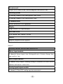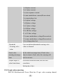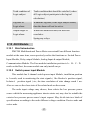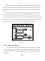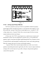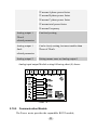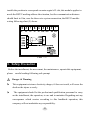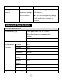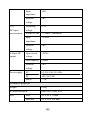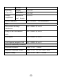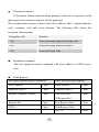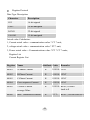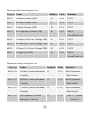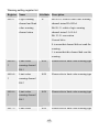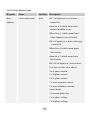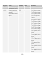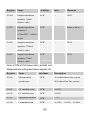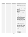
1
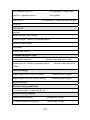
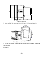
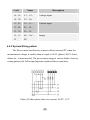
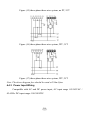
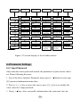
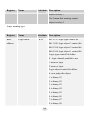
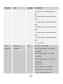
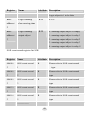
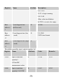
PMC200 Multifunctional Power Meter
Installation User Manual Ver1.0
Kingsine Electric Automation Co., Ltd.
Attention for PMC200 Installation
Danger and Warning
The device has danger of electricity, it will cause serious injuries even
death if you don’t avoid any case.
The device shall be installed, operated, used and maintain by professional
operator. Our company won’ t takes any responsibility if misoperation to
cause any results.
Catalogue
1. Product overview ................................................................................................6
2. Product function and characteristic .................................................................6
3. Security prevent ..............................................................................................23
4. Installation and connection ............................................................................25
5. Communication ...............................................................................................33
6. Operation.........................................................................................................34
7. Maintain and error troubleshooting ..............................................................39
Appendix A:Technical index............................................................................41
Appendix B:Register list ..................................................................................45
Appendix C Ordering Information........................................................................79
1. Product overview
PMC200 Multifunctional Power Meter is a multi-function monitoring meter,
it combines function of collecting data and control, and it can replace many kind
of meter, relay, transmitter and others components. PMC200 can be installed
different position in electricity distribution system.
PMC200 Multifunctional Power Meter has RS485 communication interface,
it can integration into any electric monitoring system and collect data and remote
control by configure management software or other industry configuration
software.
PMC200 Multifunctional Power Meter is a real measurement meter based on
real virtual value, it can do the accurate measurement for high highly nonlinear
load, it can measure accurately many electric power parameters through advanced
technology of grid frequency sampling synchronization and you can see all
measurement value and the max/min value as well as demand display value via
display screen or via software remote control.
2. Product function and characteristic
2.1 Function of Multifunctional Power Meter
Sheet 1
Host function and characteristic
Instantaneous real virtual value
Current
Phase voltage
Line voltage
Single phase and Neutral
The average of single and three phase
The average of single and three phase
6
The amount of active,
The amount of single and
reactive, apparent power
three phase
power factor
The amount of single and three phase
frequency
MIN/MAX
current
phase voltage, line voltage
general active, reactive, apparent power
general power factor
frequency
THD I and THD U
Demand and peak value
Each phase current
current value and peak value
general active, reactive, apparent power
current value and peak
value
Electric energy
Input output active electric energy
1 channel pulse output
Input output reactive electric energy
1 channel pulse output
apparent power
Electric energy multi-rate
8 multi-rate time, 4 rates can be set
Electric energy quality
Humorous aberration
current and voltage
31 times humorous analyses
current and voltage
7
Event record
100pcs SOE event record, time distinguish can reach to 1ms
Warning system
6 warning channels with configurable limit value
4 warning channels with configurable logic
Communication
RS485/MODBUS -RTU protocol
Display
Large screen STN liquid display
Real time clock
Year, month, date, minute, second
Others
Support program online upgrade
Sheet 2
Auxiliary module function and characteristic
Binary input module
8 channels binary input, time distinguish rate of status change time
can reach to 1ms
Relay output module
4 channel relay output, warning setting is available for local exceed
confine and remote control also
Analog input/output module
1 channel 4-20mA DC analog input measurement
8
1 channel 0-5V analog input measurement
2 channels 4-20mA DC analog output, transducer can be
configurable
Communication module
a) RS232 communication module
b) ProfiBus-DP communication module
c) TCP/IP Ethernet expand module
2.2 Measurement of instantaneous value
PMC200 Multifunctional Power Meter can online monitor instantaneous
value of three phase current, voltage, active power, reactive power, apparent
power, power factor and frequency, refresh once every second, the instantaneous
value can be checked via display scrren.
PMC200 Multifunctional Power Meter can connected directly without outer
connect when measure voltage less than or equal to 277V(phase)/480V(line),
otherwise, it must to request outer connect. When adopt outer PT, please pay
attention to PT linearity and accuracy level, otherwise, it will affect the whole
measurement accuracy of meter.
PMC200 Multifunctional Power Meter must to adopt CT to current
measurement with under general condition. The hypo-grade rating output of CT
request to comply with rating current input of electric power parameter test.
When adopt outer CT, please avoid open circuit during connecting, otherwise, it
will cause equipment damaged even user injured under primary excitation action
condition to cause high voltage in hopy-grade.
9
2.3 The Maximum / Minimum of instantaneous value
When real time read to Max or Min value, PMC200
Multifunctional
Power Meter will record these value to as MIN/MAX value, PMC200 will save
these value and the time which caused these value to nonvolatile location, data
won` t lose when electricity drop off suddenly, MIN/MAX value can be displayed
in display screen.
2.4 The calculation of Demand and peak value demand
DMD is the average in period of time. PMC200
Multifunctional Power
Meter adopt calculation demand of sliding area, PMC200 can be set a calculation
cycle with 1-60 minutes demand, if calculation cycle between 1-15 minutes,
DMD calculation will be refreshed every 15 second, if calculation cycle between
16-60 minutes, DMD calculation will be refreshed every 60 seconds.
Peak value demand is the DMD max value, when peak value demand
produce, PMC200 Multifunctional Power Meter will save these value and the
time which caused these value to nonvolatile location, data won` t lose when
electricity drop off suddenly, MIN/MAX value can be displayed in display screen.
refreshed every 15 second or 60 second
15 second calculation cycle
15 30 45 60...
DMD is the average
of the ending of last
calculation cycle
Time
(SEC)
sliding area
chart (1)
10
2.5 Electric energy and Electric energy pulse output
PMC200 Multifunctional Power Meter can calculate and active electric
energy & reactive electric energy of flowing into & flowing out cumulation as
well as cumulate apparent electric energy, data won` t loss when electricity drop
off, it can display in the display screen, display range: 0.0-99999999.9 kWh, it
will re-cumulate to calculate when if full calculation. Electric energy cumulation
is one time value of PT, CT.
PMC200 Multifunctional Power Meter include electric isolated 1 channel
active electric energy pulse output and 1 channel reactive electric energy pulse
output, electric energy pulse constant can be set by communication protocol,
setting range : 1000-5000 imp/kWh
2.6 Electric engergy multi-Rate
PMC200 Multifunctional Power Meter can realize subsection calculation,
time-sharing calculation, optimize electro-efficiency effectively. It adopts tine,
peak, flat, vale to calculate separately in different period.
PMC200 Multifunctional Power Meter can calculate max 8 time period
electric energy, and the based calculation unit is half and hour, which mean 8
time period in a day for 24 hours, every segment based unit is half hour, time
period starting time default is from 0 segment(it can be any segment), and the
following segment time period shall set each segment origination segment
according sort ascending to list out strictly. PMC200 Multifunctional Power
11
Metercan support max 4 rate segments, each rate can support input output active
electric energy, input output reactive electric energy and apparent electric energy,
multi-rate electric energy can be displayed in the display screen.
In order to understand multi-rate function, the following as example: if
customer everyday electricity calculation divide to 8 segment to calculate, time
segment division as below Dig.
Time
Time of
Multi-rate
starting time
Time 1
4
T1(peak)
Time 2
10
T2(vale)
Time 3
16
T3(flat)
Time 4
22
T4(tine)
Time 5
28
T1(peak)
Time 6
34
T2(vale)
Time 7
40
T3(flat)
Time 8
46
T4(tine)
1# time period starting time is from 2 o` clock, close at 5 o` clock, calculate
segment is T1, 2# time period starting time is from 5 o` clock, close at 8 o` clock,
calculate segment is T2, the rest may be deduced by analogy, 8# time period
starting time is from 23 o` clock and the second day 2 o` clock close, calculate
segment is T4. The same rate electric energy can be amalgamated together for
calculation.
2.7 Humorous and THD ratio
PMC200 Multifunctional Power Meter measure max 31 times for voltage,
12
current and humorous, it can be displayed 0-12 times humorous in display screen,
if use communication protocol, it can get 0-31 times humorous value. PMC200
Multifunctional Power Meter adopt below formula to calculate humorous:
HRh =
HRh
× 100%
HR1
PMC200 Multifunctional Power Meter can measure voltage, current THD.
The THD is ratio between humorous content and fundamental wave, it not only
provides the general situation of wave “quality”, but also effective method for
diagnosing electric energy quality. PMC200
Multifunctional Power Meter adopt
below formula to calculate THD
THD =
( H 2) 2 + ( H 3) 2 + ( H 4) 2 + ..........
× 100%
H1
2.8 Event record
In order to assist user to analyze all kinds of faults for electric system,
PMC200 Multifunctional Power Meter provide depth 100pcs SOE event record,
user can do event search orientation according to SOE event record, use
communication protocol can get SOE event record message.
PMC200 Multifunctional Power Meter can record binary state change
message, relay action message, limit value and logic warning channel state
message etc. event style.
PMC200 Multifunctional Power Meter record event happen time through
UNIX time format, distinguish can be 1ms. UNIX time is current time which
relative to the total second number of 0 second 0 minute 0 hour 1st January 1970.
13
Event record will come out following format message through communication
protocol resolution:
Event type
Event time
Binary 1 close
888 millisecond 55 minute 17 hour 19th Nov.
2010
A phase current
999 millisecond 55 minute 17 hour 19th Nov.
upper limit
2011
2.9 Warning system
PMC200 Multifunctional Power Meter has user user-defined warning
system, it can monitor all electric parameter of power grid and set requested
action. PMC200 Multifunctional Power Meter can activate max 10 warning
system synchronously, 6 limit value warning channel and 4 logic value warning
channel. When the warning began, display screen will display warning indication
and record as event.
2.9.1 Limit value warning
PMC200 Multifunctional Power Meter has 6 limit value warning channel, let
one channel effect except activate this channel, it also must set as below,
Setting content
Description
Threshold
Divide to Upper Threshold-crossing and lower
Crossing type
Limit value object
threshold-crssing
Limit value object can be 15pcs, and set
discretionarily:
0 is A phase current
14
1 is B phase current
2 is C phase current
3 is zero-sequence current
4 is max unimbalance current(Reservation)
5 is current phase lost
6 is A phase voltage
7 is B phase voltage
8 is C phase voltage
9 is AB line voltage
10 is AB line voltage
11 is CA line voltage
12 is max unimbalance voltage(Reservation)
13 is max unimbalance voltage(Reservation)
14 is voltage phase lost
Threshold
Crossing valve
User can defined threshold crossing valve
value as demand
value
Limit value
In the whole arrearage time, if limit value
warning arrearage
object return to limit value, the warning will
time
not be activate.
Output target of
When this alarm activated, the user can
value limit alarm
correlative
Spring any relays.
2.9.2 Logic value warning
PMC200 Multifunctional Power Meter has 4 Logic value warning channel,
15
Logic value warning system is activated base on the logic adjust that made onto
the monitor subject, maximum the monitoring three subjects on same time, the
parameter settings as bellow:
Setting
Description
Logic adjust type
two type: Logic Or / Logic and
Logic subject 1
Logic subject max. can reach to 15, can freely
setting:
0 means don’t adjust the subject
1 means Switch power S1;
2 means Switch power S2;
3 means Switch power S3;
4 means Switch power S4;
5 means Switch power S5;
6 means Switch power S6;
7 means Switch power S7;
8 means Switch power S8;
9 Means Value limit alarm channel RA1;
10 Means Value limit alarm channel RA1;
11 Means Value limit alarm channel RA3;
12 Means Value limit alarm channel RA4;
13 Means Value limit alarm channel RA5;
14 Means Value limit alarm channel RA6;
Logic subject 2
Same as above.
Logic subject 3
Same as above.
16
Truth condition of
Truth condition that should be satisfied ( when
Logic subject
all Logic subject participate in the logical
calculation.)
Lag time of
Within the lag time, if the logic subject return,
Logic alarm
then the alarm will not be active.
Output target of
When this alarm activated, the user can
Logic alarm
correlative
Spring any relays.
2.10 AUX Module
2.10.1
Brief introduction
PMC200 Multifunctional Power Meter can extend Four different function
module at the same time, can respectively realize the functions as: Switch Power
Input Module, Relay output Module, Analog Input & output Module,
Communication Module. The Four module installation position is A、B、C、D
notch on the Host, the same module can only install one pc.
2.10.2
Switch power input Module
This module has 8 channel switch power input Module, installation position
is A notch, used to monitoring the state signals ( like Breaker’s position signal,
Isolator’s position signal ) etc, the time resolution of state change reach 1 ms.
Also we can see the close state of the related node on the screen.
The node input voltage may choose, then selects the low pressure power
source which the measuring appliance interior starts out, may also be suitable the
exterior low pressure power source's input request. May divide into two kinds of
specifications according to the node different voltage condition: Passive node and
active node.
17
When the exterior status signal supplies a positional information merely, then
needs electric power parameter observation meter interior output node closed time
the feedback voltage signal, the outside passive contact wiring following chart (2)
shows.
When the exterior status signal not only supplies the positional information,
extra also provides the feedback voltage signal, this time the Power meter cannot
use the internal electrical power supply to output, but must adjust its interior to jump
the line hat to carry on the disposition, and makes the corresponding modification to
the wiring. The outside active contact wiring following chart (2) shows.
Chart(2)
2.10.3
Relay Output Module
The Power meter provides the expandable 4 group relay output module,
installs the position to correspond on main engine's B slot, applies in the scene
load control. The Relay control pattern may divide into long-distance and the
local pattern:
18
Local Pattern - The relay is observes and controls the meter control by the
electric power parameter, warning system connection trigger control.
Under local control pattern, relay working pattern separable: Normal, Block
system and Fixed time three kind of patterns
Normal working Pattern - When the Power meter has the warning to produce,
the warning outputs when is connected the relay, the relay closes. When warning
vanishing, the relay separates.
Block working Pattern - When the Power meter has the warning to produce,
the warning outputs when is connected the relay, the relay closes. When warning
vanishing, the relay is at the closed position. If needs the relay separation, must
suppose the relay the remote control pattern, the routing directive control relay
separation.
Fixed time Pattern - When the Power meter has the warning to produce, the
warning outputs when is connected the relay, the relay closes. The relay maintains
the movement condition in fixed time the time, when fixed time overflows, the relay
separates.
No matter the relay in above what kind of situation, after the Power Meter
loses the electricity, on the heavy electricity, the relay restores to often on status.
May examine relay's closed position on the display monitor. The relay specification
is 250Vac/5A,30Vdc/5A, if has the special demand, please when ordering carry on
the special explanation. The relay module wiring following chart (3) shows.
19
Chart(3)
2.10.4
Analog Input/Output Module
The Power parameter meter provides the expandable simulation quantity
input/output module, installs the position to correspond on main engine's C slot,
this module has 1 group 4-20mA direct current input survey, 1 group 0-5V DC
voltage input survey, 2 group 4-20mA direct current output, the direct-current
output simulation object may dispose.
4-20mA and - the 5V DC current input survey mainly uses in sensors and
transformer's and so on scene temperature, pressure survey, will simulate the
quantity signal to transform the digital signal through the Power Parameter meter
to transmit the far-end through the communication, carries on the data gathering.
May also examine the observed value on the display monitor.
2 group 4-20mA direct current output mainly uses in the scene electric
quantity transmitting instrument's application, the direct-current output simulation
(changes delivers) the object to be possible to dispose, disposition hypothesis
content following table:
20
Description
Setting Content
Analog output 1
Related to
Change delivers subject can reach 27, can
either setting one:
0 means A phase current
1 means B phase current
2 means C phase current
3 means zero sequence current
4 means A phase voltage
5 means B phase voltage
6 means C phase voltage
7 means AB line voltage
8 means BC line voltage
9 means CA line voltage
10 means A phase active power;
11 means B phase active power;
12 means C phase active power;
13 means total active power;
14 means A phase reactive power;
15 means B phase reactive power;
16 means C phase reactive power;
17 means total reactive power;
18 means A phase apparent power
19 means B phase apparent power
20 means C phase apparent power
21 means total apparent power
21
22 means A phase power factor
23 means B phase power factor
24 means C phase power factor
22 means total power factor
26 means Frequency
Analog output 1
Can freely setting
20 mA
related parameter
Analog output 1
Can be freely setting, but must smaller than
4mA
Those of 20mA.
related parameter
Analog output 2
Setting means same as Analog output 1
Analog input/output Module wiring following chart (4) shows:
Chart(4)
2.10.5
Communication Module
The Power meter provides the expandable RS232 module,
22
installs the position to correspond on main engine's D slot, this module applies in
needs the RS232 mailing address the situation, but the communication distance
should limit in 10m, uses the three-wire system connection, the RS232 module
wiring following chart (5) shows.
Chart(5)
3、Safety Precaution
Before the installment, the movement, the maintenance, operate this equipment,
please careful reading following safe prompt
Danger & Warning
This equipment existence electricity danger, if does not avoid, will cause the
death or the injure severely
The equipment should let the professional qualification personnel to carry
on the installment, the operation, to use and to maintain. Regarding not any
consequence which creates according to this handbook operation, this
company will not undertake any responsibility.
23
Electric shock, detonation and electric arc dangerous
The equipment should let the professional qualification personnel to carry
on the installment, the operation, to use and to maintain.
Be careful of the potential hazard, completes individual protection, cannot
work alone
Before carries on the installment, the operation, the use and the maintenance
of the equipment, should shut off electric power supply to this equipment.
Must use the qualified Voltage Measurement Instruments to ensure all of the
power supply is shut off.
Equipment's success movement relies on correct processing, the installment
and the operation. Neglect basically installs the request possibly to create
the personal injuries, also will possibly create to the equipment damages
Cannot carry on the bypass absolutely to the exterior fuse
Cannot cause the voltage transmitter absolutely (PT) carries on secondarily
short-circuits.
Cannot cause the current transmitter absolutely (CT) carries on the opening
secondarily. Before installment or demolition wiring should use the pipe
nipple block to carry on secondarily to CT short-circuits.
The equipment should install in an appropriate insulation and in the fire
protection engine case.
Possibly will not cause the death or the serious personal injuries according to
the above explanation operation!
24
4、Installment and Wiring
4.1 Packing List and Marker
PMC200 Multifunctional Power Meter
1 pc
Installment & User Manual
1 pc
Fixed Fastener
2 Pcs
AUX Module ( as per Purchase)
4 pcs
Screw BM2.5X64(Fixed the AUX modules)
8 pcs
4.2 Installment & Working circumstance
Operating temperature: - 25℃ ~ +55℃
Storage temperature:-35℃ ~ +70℃
Humidity:5% ~ 95%RH,No condensation.
The equipment should install in an appropriate insulation and in the fire protection
engine case.
4.3 Installment
1、PMC200
Multifunctional Power Meter size as below:
25
Chart (6) outer size
2、Insert the PMC200 meter into hole of 92.5mm X 92.5mm, as Chart (7)
Chart (7) Front side installment show
3、Use the two fastener to fixed into the left/right side of the host, to fixed the
PMC200 meter,
As chart (8).
26
Chart (8) Back side of the installment show
4、Use the screw BM2.5X64 fix the AUX module onto the host, as chart (9)
Chart (9) AUX module installment show
Note: must install the fastener before install the AUX module.
4.4 Wiring
4.4.1 Terminal and Marker
1、 Marker 1 on top of Host, as chart (10) as below:
27
Chart (10)
Marker 1
Description
Code
Name
1、3
L/+、N/-
Working Power supply input
2、4
NC、NC
Empty
5、6
NC、NC
Empty;
7、8
P2-、P2+
Reactive
power
pulse
output,
No-power-optocoupler Isolate;
9、10
P1-、P1+
Active
power
pulse
No-power-optocoupler Isolate;
11、12
B-、A+
RS485 Communication Port
13
SHD
RS485 Shielding layergrounding;
2、 Marker 2 on bottom of Host, as chart (11) as below:
chart (11) Marker 2
28
output,
Code
Name
14、16、 V1、V2、
18、20
Description
Voltage input
V3、Vn
21、22、 I1+、I1-、
Current input
23、24、 I2+、I2-、
25、26
I3+、I3-
15、17、 NC、NC、
19
Empty
NC
4.4.2 System Wiring pattern
The Power meter can directly connect without external PT when the
measurement voltage is smaller than or equal to 264V (phase) /456V (line) ,
otherwise , it must needed. The power meter support various kinds of survey
wiring pattern, the following diagrams explained these separately.
Chart (12) three phase four wire system, No PT, 3 CT
29
Chart (13) three phase four wire system, 3 PT, 3 CT
Figure (14) three-phase three-wire system, no PT, 3CT
30
Figure (15) three-phase three-wire system, no PT, 2CT
Figure (16) three-phase three-wire system, 2PT, 3CT
Figure (17) three-phase three-wire system, 2PT, 2CT
Note: The above diagram fuse should be rated at 250mA fuse.
4.4.3 Power Input Wiring
Compatible with AC and DC power input, AC input range :85-265VAC /
45-65Hz. DC input range :100-300VDC.
31
Figure (18) Power input terminal
Note: The above diagram fuse should be rated at 500mA fuse.
4.4.4
Active and reactive pulse output wiring
Pulse output is passive optocoupler isolated mode, Pull-up power supply must be
provided by exterior.
VCC
10K
P1+
P1Optoisolator
GND
Inside
Figure (19) Pulse output wiring
32
outside
5、Communication
5.1
Communication Connection
The connection method to refer to the below drawing, in the actual scene in
order to prevent signal reflection, usually the end of the RS-485 network will be
in parallel with an approximately 120-ohm resistors for signal matching.
Serial
485
Converter
Figure (20) communications wiring
5.2 Communication media
Use shielded twisted pair 22, the same network can carry up to 32
power power meter, , while the bus is not over 1200 meters without
repeaters.
33
5.3 Communication Protocol
PMC200 Power Meter supports the international generic MODBUSRTUprotocol. Agreement on the specific communication protocol, please
refer to the appropriate instructions.
Instrument can communicate with the master station prerequisite to the
communications parameters are set correctly. The communication
parameters of Power Meter include:.
Instrument Address: This is the logo on the instrument in the network,
each Power Meter has a unique address, and the user can change.
Communication baud rate: 1200,2400,4800,9600,19200(four options).
6、 Operation
6.1 Display Function
PMC200 Power Meter adopts STN LCD display with large screen and
wide visual range. Operation buttons control the LCD backlight, when the
screen saver is active, the different interface will be showed. Figure (21)
shows the various parts of the Power Meter:
A) Measurement type
B) Measurement phase
C) Numerical display
D) Unit
E) Comprehensive numerical display
F) State variables display
G) Dual-function keys
H) Current load bar graphs
34
6.2 Button Function
Power Meter has 6 buttons and the button has a dual function, as follows:
Button
Display Mode
Setting Mode
[←](I)
current shortcut key
cursor left key
[→](U)
voltage shortcut key
cursor right key
[↑](P-Q-S)
Active power, reactive power,
Page Up, modify the
apparent power shortcut key
numerical key
power factor, frequency
Page Down, modify the
shortcut key
numerical key
Active and reactive power,
Enter key
[↓](PF-F)
↓
[
](E-Time)
clock, DC input measurement
shortcut key
[■] (Menu)
Menu key
6.3 Display
The Power Meter interface shows the function menu by combining the different
electrical parameters of the matrix methods. Repeatedly press the [■] key (Menu)
to enter the menu of different functions, in different functional menu repeatedly
press the other key to display different interface. Figure (21) for the screen
displays a list of abbreviations.
35
Figure (21) screen displays a list of abbreviations
6.4 Parameter Settings
6.4.1 Input Password
Only when the correct password entered, the parameters of power meter can be
set. Please following the steps:
1. Any of the above Interface Parameter menu, press [ ← ] button to enter map
(22) password authentication interface.
2. Press [←], [→] key to move the cursor, press [↑], [↓] keys to modify the
value, enter the 3 digit password.
3. Press [ ← ] key after successful authentication the password into the
36
parameter setting interface
4. Press [ ■ ] key to exit the parameter setting state
Note: The factory default password: 000
Figure (22) password authentication interface
Press [↑], [↓] keys to select the instrument parameters to set, as shown in Figure
(23) parameter setting interface is instrument IP, address, baud rate, PT
transformation ratio, CT ratio, type of system, remove/change password ,
Hardware version and software version. These parameters setting is the same
operation with the password.
Figure (23) parameter setting interface
6.4.2
IP Setting
This parameter is used to set the device IP address. The parameters to be TCP / IP
Ethernet expansion module support to be effective.
37
6.4.3 Address Setting
This parameter is used to set the device communication address. Power
Meter supports MODBUS RTU communication protocol, the effective
address range is 1 to 247.
6.4.4 Baud Rate Setting
This parameter is used to set the device baud rate. Serial communication
speed can support 1200,2400,4800,9600 and 19200Bps.
6.4.5 PT PT transformation ratio setting
This parameter is used to set the device PT transformation ratio. Variable
ratio is equal to PT primary side rating value divides PT secondary side
rating value. If the external does not use PT, the PT transformation ratio
is 1. PT transformation ratio ranges from 1 to 9999.
6.4.6 CT transformation ratio setting
This parameter is used to set the device CT transformation ratio. Variable
ratio is equal to CT primary side rating value divides CT secondary side
rating value. If the external does not use CT, the CT transformation ratio is
1. CT transformation ratio ranges from 1 to 9999.
6.4.7 System type setting
The parameters of the measurement system used to set the device type.
Support for four line star and delta measurement mode. See connection
methods on four specific content.
6.4.8 Clear
The parameters used for device input and output active and reactive power,
multi-rate power, maximum and minimum, demand, SOE event record cleanup
menu.
38
6.4.9
Version Information
To facilitate equipment maintenance, provide hardware and software version
information for inquiries.
7、Maintenance and Troubleshooting
Possible problems
Possible Cause
Possible solutions
The power to
Power supply is
■Confirm the L / +, N / - terminal
impose control on
not connected to
to add the power supply
the meter without
the meter
■ Check the power supply fuse is
burned;
display;
Meter data shown is
Voltage
■Check the system rated voltage,
not accurate or not
measurement is
rated frequency, system type, PT
you expect;
not correct;
transformation ratio is set correctly;
■ there is enough voltage on
voltage input terminal
■Check the input fuse is burned;
■ Check the neutral connection is
reliable;
current
■ Check the system rated current,
measurement is
rated frequency, system type, CT
not correct;
transformation ratio is set correctly;
■Current input wiring is correct;
■Check the system rated voltage,
power
measurement is
rated current, rated frequency,
not correct;
system type, PTCT transformation
39
ratio is set correctly;
■ Voltage and current
corresponding to the phase is
correct;
■ Voltage, current
transmitterpolarity (same name as
the client) are correct;
■ Check the mailing address
can not
Instrument
communicate with
parameter settings
settings are correct;
the instrument
are not correct
■ Check the communication baud
remotely by
rate settings are correct;
computer
■ in the same RS485 line, mailing
address settings are repeated;
Communication
■Check the meter communication
line is not properly
cable;
connected
Input / output state
input / output
■ According to the external node
does not change;
operation voltage
type, check whether the correct
is not correct
jumper inside the module;
■ Check the external wiring is
correct, the parameters match;
Relay does not
operate;
Instrument
■ Check the relay operation mode
parameter settings
settings are correct;
are not correct;
Does not receive
■ Check the meter
control commands;
communication cable;
40
Analog output is not
Instrument
■ Check the analog output object is
correct
parameter settings
set correctly;
are not correct;
■ Check the corresponding analog
value on the lower settings are
correct;
Appendix A: Specifications
Electrical Characteristics
Measurement Type
Three-phase three-wire AC system,
three-phase four-wire communication
system;
Sampling rate per cycle: 64 times
Data refresh rate
1S;
Measurement
Current
0.2%
Accuracy
Voltage
0.2%
Power
0.5%
Frequency
0.05Hz
Active
1.0%
Energy
Reactive
2.0%
Energy
Input voltage
AI
0.5%
AO
0.5%
Measuring
3 X 220/380V (Direct Access)
41
characteristics
voltage
3 X 57.7/100V(Via transmitterAccess)
Allowed
1.2 times / continuous
overload
Input
1.8MΩ
impedance
Input current
characteristics
Measuring
5A or 1A (Via transmitterAccess)
current
Allowed
1.2 times / continuous
overload
Input
<0.1Ω
impedance
Binary input
Working
12~24 VDC
voltage
Input
12KΩ
impedance
Isolation
2KV
voltage
Relay output
Node Type
Mechanical shock
Node capacity
220 VAC/5A、30 VDC/5A
4-20mA
Measuring
4-20mA
input
current
measurement
Allowed load
1.2 times / continuous
1.2 times / continuous
Allowed load
42
Input
10Ω
impedance
Isolation
2KV
voltage
0-5V
Measuring
0-5V
DC input
voltage
measurement
Allowed Load
1.2 times / continuous
Input
12.5KΩ
impedance
Isolation
2KV
voltage
4-20mA DC
Open circuit
output
voltage
15VDC
Load capacity
≤600Ω
Isolation
2KV
voltage
Power supply
AC
85~265 VAC/45-65Hz
DC
100~300 VDC
Power
< 3W
Mechanical properties
Weight
0.5kg
IP protection grade
panel IP52, body IP30
Size
Host
96 X 96 X 72 mm
Host and
96 X 96 X 120 mm
43
module
Operating
Display
-20~70℃
temperature
Instrument
-25~70℃
Storage
temperature
instrument
-40~85℃
and display
Relative humidity
5% - 90%RH, No condensation
EMC
Electrostatic discharge
IEC 61000-4-2,Level 4
interference
Group of anti-fast transient
IEC 61000-4-4,Level 4
pulse
Anti-impact
IEC 61000-4-5,Level 3
Anti-frequency magnetic field
IEC 61000-4-8,Level 3
Electrical insulation performance
Insulation resistance
GB/T13729,>50MΩ
frequency withstand voltage
GB/T13729,AC 2KV 50Hz /1min
Impulse voltage
GB/T13729,5KV,1.2/50us
44
Appendix B: Register List
Overview of communication protocol
MODBUS RTU protocol communication protocol and standard serial RS485
communication port are used for Power Meter. Information transfer mode is
asynchronous, 1 start bit, 8 data bits, 1 stop bit, no parity. Each package contains
the address of frame data field, function code field, data field and checksum field.
The maximum length of a data package is 255 bytes.
Address field
Parcels from the station address field length is one byte. A single device address
range from the station 1 to 247. If the station receives an address from the address
field information consistent with its own parcel, the parcel should be included in the
implementation of the command. Parcels from the station in response to address the
domain of their own.
Function code field
Parcels in the domain of length onebyte, to inform what action should be
implemented from the station. Response from the station master package should
contain the same operation requested domain bytes.
45
Related function code as following:
Function
Meaning
Function
Read register
access to the current power meter’s values of one
Code
0x03
or more consecutive registers
0x10
Set register
the specified value written to power meter of one
or more consecutive registers
0x05
Bite setting
control a relay or a bit of a register of the current
power meter
Data Domain
Data field length of the parcel is determined according to its specific function.
Data field using big byte before the low byte in the latter mode;
Check Domain
MODBUS-RTU mode 16-bit CRC checksum. Equipment should be sent parcel
data for each calculation of CRC16, the final results placed into the checksum field.
Package should also be on the receiving device in each of the data (in addition to
checking the domain outside) for CRC16 calculation, compare results and verify the
domain. Only the same package can be accepted.
46
Exception response:
If the master station sends an illegal package to this Set, or requests a valid
data register, the exception response will be generated.
The exception data response consist of the slave address, 80H + original function
code, exception code and verify domains. The following table shows the
exception code meaning:
Exception code
Remarks
01H
Received illegal operate Function code
02H
Received illegal Register Address
03H
Received illegal Data
Broadcast command
This Set support broadcast command with slave address as 0X00 but no
echo.
Read Register
The master station sends a command
Slave station normal response
Slave Address
1 byte
Slave Address
1 byte
Function code 03
1 byte
Function code 03
1 byte
Register Originate Address
2 byte
Data Area byte
1 byte
(2*Register Pcs )
Register Pcs
2 byte
First Register Data
2 byte
C RC 16
2 byte
N-th Register Data
-----
C R C 16
2 byte
47
●
Setting Register
The master station sends a command
Slave station normal response
Slave Address
1 byte
Slave Address
1 byte
Function code 10
1 byte
Function code 10
1 byte
Register Originate Address
2 byte
Register Originate Address
2 byte
Register Pcs
2 byte
Register Pcs
2 byte
Data Area byte No.
1 byte
CRC16
2 byte
(2*Register Pcs )
First Register Data
2 byte
N-th Register Data
- - -- -
C R C 16
2 byte
●
Bit-Write Register
Bit-write register can control relays or bit register by send control commands:
that 0xFF00 as write 1 (closed a relay)0x0000 as write 0 (release of a relay),
Others are all invalid.
Master sends the command:
Slav Address
Function code
Originate Address
control command
CRC16
1 byte
05
2 byte
2 byte
2 byte
Normal response from Slave station:
Slav Address
Function code
Originate Address
Register State
CRC16
1 byte
05
2 byte
2 byte
2 byte
48
Register Protocol
Data Type Description:
Character
Description
INT
16-bit signed
UINT
16-bit unsigned
LONG
32-bit signed
ULONG
32-bit unsigned
Actual value Calculation:
1, Current actual value = communication value * CT * unit;
2, voltage actual value = communication value * PT * unit;
3, Power actual value = Communications value * PT * CT * units;
Register List
Current Register List
Register Name
Attribute Unite
Remarks
40001
A-Phase Current
R
0.001A UINT
40002
B-Phase Current
R
0.001A UINT
40003
C-Phase Current
R
0.001A UINT
40004
Zero-sequence Current
R
0.001A UINT
40005
3-Phase Current
R
0.001A RESV, Overall
back to 0
R
0.1%
average Value
40006
Max. Unbalanced current
49
RESV, Overall back to 0
Voltage Register List
Register
Name
40007
A-B Line Voltage
40008
Attribute
Unite
Remarks
R
0.01V
UINT
B-C Line Voltage
R
0.01V
UINT
40009
C-A Line Voltage
R
0.01V
UINT
40010
Line Voltage
R
0.01V
UINT
R
0.1%
RESV,
average Value
40011
Max. unbalanced
Line Voltage
Overall back to 0
40012
A-Phase -Phase Voltage
R
0.01V
UINT
40013
B-Phase -Phase Voltage
R
0.01V
UINT
40014
C-Phase -Phase Voltage
R
0.01V
UINT
40015
Phase Voltage average
R
0.01V
UINT
R
0.1%
RESV,
Value
40016
Max. unbalanced
Phase Voltage
40017
Voltage N-R
Overall back to 0
R
0.01V
RESV, Overall back to
0
Power Register List
Register Name
Attribute Unite
40018
A-Phase Active Power (L)
R
0.1W
40019
A-Phase Active Power (H)
R
0.1W
40020
B-Phase Active Power (L)
R
0.1W
50
Remarks
LONG
LONG
Register
Name
40021
B-Phase Active Power (H)
R
0.1W
40022
C-Phase Active Power (L)
R
0.1W
40023
C-Phase Active Power (H)
R
0.1W
40024
Overall Active Power (L)
R
0.1W
40025
Overall Active Power (H)
R
0.1W
40026
A-Phase Reactive Power (L)
R
0. 1Var
40027
A-Phase Reactive Power (H)
R
0. 1Var
40028
B-Phase Reactive Power (L)
R
0. 1Var
40029
B-Phase Reactive Power (H)
R
0. 1Var
40030
C-Phase Reactive Power (L)
R
0. 1Var
40031
C-Phase Reactive Power (H)
R
0. 1Var
40032
Overall Reactive Power (L)
R
0. 1Var
40033
Overall Reactive Power (H)
R
0. 1Var
40034
A-Phase Apparent power (L)
R
0.1VA
40035
A-Phase Apparent power (H)
R
0. 1VA
40036
B-Phase Apparent power (L)
R
0. 1VA
40037
B-Phase Apparent power (H)
R
0. 1VA
40038
C-Phase Apparent power (L)
R
0. 1VA
40039
C-Phase Apparent power (H)
R
0. 1VA
40040
Overall Apparent power (L)
R
0. 1VA
40041
Overall Apparent power (H)
R
0. 1VA
Attribute
51
Unite
Remarks
LONG
LONG
LONG
LONG
LONG
LONG
ULONG
ULONG
ULONG
ULONG
Power factor Register List
Register
Name
40042
A-Phase Power factor
40043
Attribute
Unite
Remarks
R
0.001
INT
B-Phase Power factor
R
0.001
INT
40044
C-Phase Power factor
R
0.001
INT
40045
Overall Power factor
R
0.001
INT
Frequency Register List
Register
Name
40046
Frequency
Attribute
R
Unite
Remarks
0.01Hz
UINT
Energy Register List
Register
Name
40047
Input Active Energy(L)
40048
Unite
Remarks
R
0.1kWh
ULONG
Input Active Energy(H)
R
0.1kWh
40049
Input Reactive Energy(L)
R
0.1kVarh
40050
Input Reactive Energy(H)
R
0.1kVarh
40051
Output Active Energy(L)
R
0.1kWh
40052
Output Active Energy(H)
R
0.1kWh
40053
Output Reactive Energy(L)
R
0.1kVarh
40054
Output Reactive Energy(H)
R
0.1kVarh
40055
Overall Apparent Energy (L)
R
0.1kVAh
40056
Overall Apparent Energy (H)
R
0.1kVAh
Attribute
Remarks: 40057-40069 reserve with forbidden.
52
ULONG
ULONG
ULONG
ULONG
Harmonic distortion Register List
Register Name
Attribute Unite
Remarks
40070
A-Phase Current THD
R
0.1%
UINT
40071
B-Phase Current THD
R
0.1%
UINT
40072
C-Phase Current THD
R
0.1%
UINT
40073
Zero-sequence Current THD
R
0.1%
RESV,
Overall back to 0
40074
A-Phase (A-B Line )Voltage THD
R
0.1%
UINT
40075
B-Phase (B-C Line )Voltage THD
R
0.1%
UINT
40076
C-Phase (C-A Line )Voltage THD
R
0.1%
UINT
40077
Voltage N-R THD
R
0.1%
RESV,
Overall back to 0
Harmonic Analysis Register List
Register
40078+31
Attribute
Name
A-Phase Current Harmonic
R
Unite
Remarks
0.1%
Refer Harmonic
-Data Stencil
Contents
40110+31
B-Phase Current Harmonic
R
0.1%
Contents
40142+31
-Data Stencil
C-Phase Current Harmonic
R
0.1%
Contents
40174+31
Refer Harmonic
Refer Harmonic
-Data Stencil
Zero-sequence Current
R
Harmonic Contents
0.1%
RESV,Overall
back to 0
53
Register
40206+31
Name
Attr
Unite
Remarks
A-Phase (A-B Line )Voltage
R
0.1%
Refer
Harmonic Contents
40238+31
-Data Stencil
B-Phase (B-C Line ) Voltage
R
0.1%
Harmonic Contents
40270+31
C-Phase (C-A Line ) Voltage
Voltage
N-R
Refer
Harmonic
-Data Stencil
R
0.1%
Harmonic Contents
40302+31
Harmonic
Refer
Harmonic
-Data Stencil
Harmonic
R
0.1%
Contents
RESV,Overall
back to 0
Remarks: 40334~40349reserve with forbidden.
Harmonic Data Stencil
Register
Name
Attribute Unite Remarks
Base Address
H0 DC Contents
R
0.1% UINT
Base Address +1
H1 - Harmonic Contents
R
0.1% UINT
Base Address +2
H2 Harmonic Contents
R
0.1% UINT
Base Address +3
H3 Harmonic Contents
R
0.1% UINT
------
------
------
------ ------
Base Address +30
H30 Harmonic Contents
R
0.1% UINT
Base Address +31
H31 Harmonic Contents
R
0.1% UINT
Multi-tariff Energy Register List
Register
Name
Attribute
54
Unite
Remarks
Register
40350
Name
Overall Multi-tariff
Unite
Remarks
R/W
-
0 as No;Max. 8pcs
R/W
-
0~47, 24h divide
Attribute
Timeslot Pcs
40351
Timeslot 1 Originate Time
as 48pcs Timeslot
40352
Timeslot 1rate
R/W
-
0~3 as 4pcs rate
0
as
Peak;1
as
Valley;
2 as Flat;3 as Sharp
40353
Timeslot 2 Originate Time
R/W
-
0~47
40354
Timeslot 2 Rate
R/W
-
0~3
40355
Timeslot 3 Originate Time
R/W
-
0~47
40356
Timeslot 3 Rate
R/W
-
0~3
40357
Timeslot 4 Originate Time
R/W
-
0~47
40358
Timeslot 4 Rate
R/W
-
0~3
40359
Timeslot 5 Originate Time
R/W
-
0~47
40360
Timeslot 5 Rate
R/W
-
0~3
40361
Timeslot 6 Originate Time
R/W
-
0~47
40362
Timeslot 6 Rate
R/W
-
0~3
40363
Timeslot 7 Originate Time
R/W
-
0~47
40364
Timeslot 7 Rate
R/W
-
0~3
40365
Timeslot 8 Originate Time
R/W
-
0~47
40366
Timeslot 8 Rate
R/W
-
0~3
55
Register
Name
Attribute
Unite
Remarks
40367+9
Rate 0 Energy
R
-
Refer next table:
40377+9
Rate 1 Energy
R
-
Rate
40387+9
Rate 2 Energy
R
-
Stencil
40397+9
Rate 3 Energy
R
-
Structure
Rate Structure Stencil
Register
Name
Base Address
Input Active Energy(L)
R
0.1kWh
Base Address +1
Input Active Energy(H)
R
0.1kWh
Base Address +2
Input Reactive Energy(L)
R
0.1kVarh
Base Address +3
Input Reactive Energy(H)
R
0.1kVarh
Base Address +4
Output Active Energy(L)
R
0.1kWh
Base Address +5
Output Active Energy(H)
R
0.1kWh
Base Address +6
Output Reactive Energy(L)
R
0.1kVarh
Base Address +7
Output Reactive Energy(H)
R
0.1kVarh
Base Address +8
Overall Apparent Energy (L)
R
0.1kVAh
Base Address +9
Overall Apparent Energy (H)
R
0.1kVAh
Attribute Unite
Remarks
ULONG
Min. /Max. Value Register List
Register
Name
Attribute
Unite
40407+9
Min. /Max. Current
R
0.001A
40417+9
Min. /Max. Line Voltage L-L
R
0.01V
56
Remarks
Register
Name
Attribute Unite
40427+9
Min. /Max. -Phase Voltage L-N
R
0.01V
40437+9
Min. /Max. Overall Active
R
0.1W
Refer Min.
Power
40447+9
Min. /Max. Overall Reactive
R
0.1Var
R
0.1VA
Power
40457+9
Remarks
Min. /Max. Overall Apparent
/Max.
Value Stencil
power
40467+9
Min. /Max. Overall Power factor
R
0.001
40477+9
Min. /Max. Frequency
R
0.01Hz
40487+9
Min. /Max. Current THD
R
0.1%
40497+9
Min. /Max. Voltage THD
R
0.1%
Min. /Max. Value Stencil
Register
Name
Base Address
Min. Value Occurred Time
Attribute Unite
R
1S
(L)
ULONG
ULONG
R
-
Base Address
Min. Value Occurred Time
+1
(H)
Base Address
Min. Value (L)
R
-
Min. Value (H)
R
-
UNIX
Time form
+2
Base Address
Remarks
+3
57
LONG
Register
Name
Base Address
Min. Value Phase Place
Attribute Unite
R
-
+4
Remarks
0 as
No-Phase
1 as A-Phase
2 as B-Phase
3 as C-Phase
Base Address
Max. Value Occurred Time
+5
(L)
Base Address
Max. Value Occurred Time
+6
(H)
Base Address
Max. Value (L)
R
-
Max. Value (H)
R
-
Max. Value Phase
R
-
R
1S
ULONG
R
-
UNIX
Time form
LONG
+7
Base Address
+8
Base Address
+9
0 as
No-Phase
1 as A-Phase
2 as B-Phase
3 as C-Phase
Demand Register List
Register
Name
40507
Demand Compute cycles
R/W
min
1~60
40508
A-Phase Current Demand
R
0.001A
UINT
40509
B-Phase Current Demand
R
0.001A
UINT
Attribute Unite
58
Remarks
Register
Name
Attribute
Unite
40510
C-Phase Current Demand
R
0.001A UINT
40511
Zero-sequence Current Demand
R
0.001A UINT
40512
Overall Active Power Demand (L)
R
0.1W
40513
Overall Active Power Demand (H)
R
0.1W
40514
Overall Reactive Power Demand (L)
R
0.1Var LONG
40515
Overall Reactive Power Demand (H)
R
0.1Var
40516
Overall Apparent power Demand (L)
R
0.1VA
40517
Overall Apparent power Demand (H)
R
0.1VA
Attribute Unite
Remarks
Remarks
LONG
ULONG
Peak Demand Register List
Register
Name
40518+3
A-Phase Current Peak
R
0.001A Refer Peak Demand
Demand
40522+3
Stencil
B-Phase Current Peak
R
0.001A Refer Peak Demand
Stencil
Demand
40526+3
C-Phase Current Peak
R
0.001A Refer Peak Demand
Stencil
Demand
40530+3
Zero-sequence Current Peak
R
0.001A Refer Peak Demand
Demand
40534+3
Stencil
Overall Active Power Peak
R
Demand
40538+3
0.1W
Refer Peak Demand
Stencil
Overall Reactive Power
R
Peak Demand
0.1Var Refer Peak Demand
Stencil
59
Register
Name
40542+3
Overall Apparent power
Attrbute
R
Unite
Remarks
0.1VA
Refer Peak Demand
Peak Demand
Stencil
Peak Demand Stencil
Register
Name
Base Address
Peak Occurred Time (L)
R
1S
ULONG
Base Address +1
Peak Occurred Time (H)
R
-
UNIX Time form
Base Address +2
Peak Demand (L)
R
-
LONG
Base Address +3
Peak Demand (H)
R
-
Attribute Unite Remarks
Remote control Register List
Register
Name
Attribute
Remarks
40546
On-off Input &
R
Digital 00~07:correspond Switch
Relay Output State
S1~S8;
Digital 08~11:correspond Relay
RL1~RL4;
Digital 12~15: remain
Each Digital Value:
0 as Switch or Relay Off;
1 as Switch or Relay On;
40547
Relay 1Working
R/W
High byte :
0 as Local Control Model;
model
1 as Remote Control Model;
Low byte :
60
Register
Attribute
Name
Remarks
0 as Normal Working model;
1 as Locking Working model;
2 as Timing Working model;
40548
Relay 1 Timer value
R/W
0-3600
40549
Relay 2 Working
R/W
Alike Relay 1
model
40550
Relay 2 Timer value
R/W
0-3600
40551
Relay 3 Working
R/W
Alike Relay 1
model
Relay control write register (function code 0x05)
Register
Name
40555
Relay 1
Attribute
W
Description
Can be control as remote control mode
Write 0xffoo relay close
Write 0x0000 relay disconnection
40556
Relay 2
W
Same as above
40557
Relay 3
W
Same as above
40558
Relay 4
W
Same as above
61
Warning setting register list
Register
Name
40559
Logic warning
Attribute Description
R
Bit 00-05: relative limit value warning
channel and limit
channel status RA1-RA6
value warning
Bit 08-11: relative logic warning
channel status
channel status LA1-LA4
Bit 12-15: reservation
Current bit is:
0 is mean that channel did not send the
warning
1 is mean that this channel had sent the
warning
40560+
Limit value
3
warning channel
R/W
Please refer to limit value warning type
R/W
Please refer to limit value warning type
R/W
Please refer to limit value warning type
R/W
Please refer to limit value warning type
RA1
40564+
Limit value
3
warning channel
RA2
40568+
Limit value
3
warning channel
RA3
40572+
Limit value
62
Register
Name
3
warning channel
Attribute
Description
W
RA4
40576+
Limit value
3
warning channel
R/W
Please refer to limit value warning type
R/W
Please refer to limit value warning type
R/W
Please refer to logic warning type
R/W
Please refer to logic warning type
R/W
Please refer to logic warning type
R/W
Please refer to logic warning type
RA5
40580+
Limit value
3
warning channel
RA6
40584+
Logic warning
3
channel LA1
40588+
Logic warning
3
channel LA2
40592+
Logic warning
3
channel LA3
40596+
Logic warning
3
channel LA4
63
Limit value warning type
Register
Name
Base
Limit value mode
Attribute Description
R/W
Bit 7 of high byte is activation
address
control bit
when bit is 0 which mean limit
channel prohibit to use
When bit is 1 which meant limit
value channel to be activated
Bit 6 of high byte is limit value type
control bit
When bit is 0 which mean upper
limit action
when bit is 1 which mean lower
limit action
Bit 5-00 of high byte: (reservation)
Low byte is limit value object
0 is A phase current
1 is B phase current
2 is C phase current
3 is zero-sequence current
4 is max unbalance current;
(reservation)
5 is current phase lost
6 is A phase voltage
7 is B phase voltage
64
Register
Name
Attribute
Description
8 is C phase voltage
9 is AB line voltage
10 is BC line voltage
11 is CA line voltage
12 is max unbalance voltage
(reservation)
13 is max unbalance
voltage(reservation)
14 is voltage lost
Limit value
R/W
UINT
Base
Limit value
R/W
0-255
address+
warning
2
slow-moving time
Base
limit value warning R/W
against output object
Base
address
+1
address+
No.0 mean that warning output
object is empty
3
No.1 mean that warning output
object is relay 1
No.2 mean that warning output
object is relay 2
No.3 mean that warning output
65
Register
Name
Attribute Description
object is relay 3
No.4 mean that warning output
object is relay 4
Logic warning type
Register
Name
Base
Logic mode
Attribute Description
R/W
Bit 15-12: logic type control bit
address
Bit 11-08: logic object 3 control bit
Bit 07-04: logic object 2 control bit
Bit 03-00: logic object 1 control bit
Logic type control bit define:
0 : logic channel prohibit to use
1 mean as logic
2 mean or logic
Logic object control bit define:
0: non-judge this object
1 is binary S1
2 is binary S2
3 is binary S3
4 is binary S4
5 is binary S5
6 is binary S6
7 is binary S7
8 is binary S8
66
Register
Name
Attribute Description
9 is limit value warning channel
RA1
10 is limit value warning channel
RA2
11 is limit value warning channel
RA3
12is limit value warning channel
RA4
13 is limit value warning channel
RA5
14 is limit value warning channel
RA6
15: reservation
Base
Real value
address+
condition
R/W
Bit 15-03: reservation
Bit 02: logic object 3 real value
1
condition
Bit 01: logic object 2 real value
condition
Bit 00: logic object 1 real value
condition
Current bit is:
0: logic object is 0 to be fake
Logic object is 1 to be real
1: logic object 0 to be real
67
Register
Name
Attribute Description
Logic object is 1 to be fake
Base
Logic warning
address+
slow-moving time
R/W
0-255
R/W
0: warning output object is empty
2
Base
Logic warning
address+
output object
1: warning output object is relay 1
3
2: warning output object is relay2
3: warning output object is relay3
4: warning output object is relay 4
SOE event record register list SOE
Register
Name
Attribute Description
40600+
SOE event record
R
3
1
40604+
SOE event record
3
2
40608+
SOE event record
3
3
40612+
SOE event record
3
4
40616+
SOE event record
3
5
Please refer to SOE event record
type
R
Please refer to SOE event record
type
R
Please refer to SOE event record
type
R
Please refer to SOE event record
type
R
Please refer to SOE event record
type
--------------68
Register
Name
Attribute Description
40980+
SOE event record
R
3
96
40984+
SOE event record
3
97
40988+
SOE event record
3
98
40992+
SOE event record
3
99
40996+
SOE event record
3
100
Please refer to SOE event record
type
R
Please refer to SOE event record
type
R
Please refer to SOE event record
type
Please refer to SOE event record
R
type
Please refer to SOE event record
R
type
SOE event record type SOE
Register
Name
Base
Event type
Attribute Description
R
address
The max word bit is event
change status
Current bit is 0 to be change
status 1→0
Current bit is 1 to be change
status 0→1
The rest word bit is event type
0-7 relative to binary S1-S8
8-11 relative to relay RL1-RL4
12-17 is limit value warning
69
Register
Attribute Description
Name
RA1-RA6
18-21 is logic warning
LA1-LA4
Other value invalidation
0x7FFF is event to be empty
Base
Event happen time
address+
(millisecond)
R
0-1000
R
U LONG
1
Base
address
Event happen time (low
word)
UNIX time format
+2
Base
address
Event happen time (high
R
word)
+3
Simulation quantity input output register list
Register
Name
Attribute
Unite
Remarks
41000
Input simulation
R
0.01mA
UINT
R
0.001V
UINT
quantity 1
4-20mADC
measurement value
41001
Input simulation
quantity 2 0-5VDC
70
Register
Name
Attribute Unite
Remarks
R/W
0 is A phase current
measurement value
41002
Output simulation
-
quantity 1
1 is B phase current
4-20mADC relative
2 is C phase current
object
3 is zero-sequence
current
4 is A phase voltage
5 is B phase voltage
6 is C phase voltage
7 is AB line voltage
8 is BC line voltage
9 is CA line voltage
10 is A phase active
power
11 is B phase active
power
12 is C phase active
power
13 is general active
power
14 is A phase reactive
power
15 is B phase reactive
power
71
Register
Name
Attribute Unite
Remarks
16 is C phase reactive
power
17 is general reactive
power
18 is A phase apparent
power
19 is B phase apparent
power
20 is C phase apparent
power
21 is general apparent
power
22 is A phase power
factor
23 is B phase power
factor
24 is C phase power
factor
25 general power factor
26 is frequency
Other value invalidation
41003
Input simulation
R/W
-
quantity 1 20mA
relative value
72
UINT
Register
Name
Attribute
41004
Output simulation
R/W
-
UINT
R/W
-
Same as above;
R/W
-
UINT
R/W
-
UINT
Unite
Remarks
quantity 1 4mA
relative value
41005
Output simulation
quantity 2
4-20mADC
relative
object
41006
Output simulation
quantity 2 20mA
relative value
41007
Output simulation
quantity 2 4mA
relative value
Note: 41008-41009 reservation, prohibit visit
Measurement setting and status register list
Register
Name
41100
Measurement
Attribute
R/W
system type
Description
30 is three/three line system
40 is three/four line system
41101
CT variable ratio
R/W
0-9999
41102
PT variable ratio
R/W
0-9999
41103
Equipment address
R/W
1-247
41104
Communication
R/W
0=1200;1=2400;2=4800;
73
Register
Name
Attribute
baud rate
41105
Equipment
Description
3=9600;4=19200;
R/W
Reservation, total return to 0
R/W
Reservation, total return to 0
R/W
Reservation, total return to 0
R/W
1000-5000
R/W
1000-5000
R
0 : had refreshed
password
41106
IP address (low
word)
41107
IP address (high
word)
41108
Active electric
energy pulse
constant
41109
Reactive electric
energy pulse
constant
41110
Humorous refresh
status
41111
Humorous refresh
1: is calculating
Reservation, total return to 0
R/W
Reservation, total return to 0
frequency
41112
Screen protection
Bit 15: phase voltage display
R/W
interface
display setting
Bit 14: line voltage display
interface
Bit 13: phase current display
interface
Bit 12: active power display
74
Register
Name
Attribute
Description
interface
Bit 11: reactive power display
interface
Bit 10: apparent power display
interface
Bit 09: power factor display
interface
Bit 08: frequency display
interface
Bit 07: input active electric
energy display interface
Bit 06: output active electric
energy display interface
Bit 05: input reactive electric
energy display interface
Bit 04: output reactive electric
energy display interface
Bit 03: date display interface
Bit 02: time display interface
Bit 01: input simulation
quantity 1 display interface
Bit 00: input simulation 2
display interface
Current bit is :
0: no display
75
Register
Name
Attribute
Description
1: display
41113
System time (low
R/W
ULONG
word)
41114
System time (high
R/W
word)
41115
The time of last
R
0-255
R
ULONG
electricity
restoration
41116
The last time for
electricity time
(low word)
41117
The last time for
R
electricity time
(high word)
41118
The last time for
R
Reservation, total return to 0
lost time(low
word)
41119
The last time for
R
lost time(high
word)
41120
House dog
R
Reservation, total return to 0
R
Reservation, total return to 0
restoration times
41121
The last time of
76
Register
Name
Attribute
Description
house dog
restoration time
(low word)
41122
The last time of
R
house dog
restoration time
(high word)
41123
Equipment
The highest bit is revised year
R
hardware version
The second high bit is revised
month
(low word)
41124
Equipment
High bit is revised date
R
Low bit is revised times
hardware version
(high word)
41125
Equipment
R
The highest bit is revised year
The second high bit is revised
software version
month
(low word)
41126
Equipment
High bit is revised date
R
Low bit is revised times
software version
(high word)
41127
Equipment
The highest bit is revised year
R
code(low word)
41128
Equipment
The second high bit is revised
month
R
High bit is revised date
code(high word)
Low bit is revised times
77
Register
Name
41129
Equipment
Attribute
R
nameplate
Description
High bit is rating voltage
1=100V;2=220V;
3=380V;6=660V;
Low bit is rating current
1=1A;5=5A;
Reset refresh control bit write register(function code 0x05)
Register
Name
41130
Electric energy reset
41131
Multi rate electric
Attribute
W
W
energy reset
Description
Write 0xFF00 clear away
Write 0xFF00 clear away
41132
Max Min value reset
W
Write 0xFF00 clear away
41133
Demand reset
W
Write 0xFF00 clear away
41134
SOE event record reset
W
Write 0xFF00 clear away
41135
System restoration
W
Write 0xFF00 restoration
41233
Refresh to
W
manufacturing factory
setting
Note: 41136-41199 reservation, prohibit visit
78
Write 0xFF00 to refresh to
manufacturing factory setting
Appendix C Ordering Information
PMC200 Multifunctional Power Meter Selection Guide
Model :PMC200-A-B-C-D-E-F-G
A Rated measuring voltage, current
1
57.7/100V,5A
2
57.7/100V,1A
3
220/380V,5A
4
220/380V,1A
B Power system frequency
1
50Hz
2
60Hz
C Power Supply
1
85~265 VAC/45-65Hz,100~300 VDC
D Host A slot Expansion module
0
No
1
8-channel binary input module
2
6-channel binary input module
E Host B slot Expansion module
0
No
1
4 Relay Output Module
F Host C slot Expansion module
0
No
1
Analog Input / Output Module
1 AI : 4-20mA
1 AI : 0-5V
79
2 AO : 4-20mA
G Host D slot Expansion module
0
No
1
RS232 Communication module
2
TCP/IP module
3
ProfiBus-DP module
Warning: A Host can match maximum 4 modules
Example:Ordering model is : PMC200-3-1-1-1-1-1-0
That is , PMC200 with Rated measuring voltage, current: 220/380V 5A,
Power system
Frequency :50Hz,Power Supply :85~265 VAC/45-65Hz,8-channel
binary input module,
4 Relay Output Module and Analog Input / Output Module
80
Note:
The information provided in the manual may be slightly different due
to different software version.
right to interpret the said information reserved by Shenzhen Kingsine
Electric Automation Co., Ltd.
Kingsine Electric Automation Co., Ltd.
Address:6/F, Block 4-CD, TianAn Cyber Park,
Shenzhen 518040, China
Fax:+86 755-88352611
Technical support:+86-755-88352590
http:// www.kingsine.com.cn
E-mail:[email protected]
83418941