1
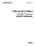
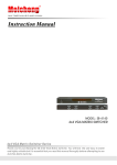
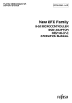
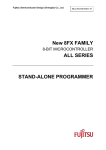
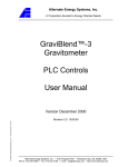
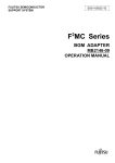
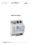
Fujitsu Semiconductor (Shanghai) Co., Ltd.
Application Note
MCU-AN- 500066-E-11
F²MC-8FX FAMILY
8-BIT MICROCONTROLLER
MB95310/370 SERIES
INFRARED REMOTE
FUNCTION API
APPLICATION NOTE
Infrared Remote Function API V1.1
Revision History
Revision History
Date
2009-11-06
2011-03-17
Author
Jane Li
Jane Li
Change of Records
V1.0, First draft
V1.1, modified Chinese remark
This manual contains 20 pages.
1. The products described in this manual and the specifications thereof may be changed without prior notice.
To obtain up-to-date information and/or specifications, contact your Fujitsu sales representative or Fujitsu
authorized dealer.
2. Fujitsu will not be liable for infringement of copyright, industrial property right, or other rights of a third party
caused by the use of information or drawings described in this manual.
3. The contents of this manual may not be transferred or copied without the express permission of Fujitsu.
4. The products contained in this manual are not intended for use with equipments which require extremely
high reliability such as aerospace equipments, undersea repeaters, nuclear control systems or medical
equipments for life support.
5. Some of the products described in this manual may be strategic materials (or special technology) as defined
by the Foreign Exchange and Foreign Trade Control Law. In such cases, the products or portions thereof
must not be exported without permission as defined under the law.
© 2009 Fujitsu Semiconductor (Shanghai) Co., Ltd
MCU-AN- 500066-E-11 – Page 2
Infrared Remote Function API V1.1
CONTENTS
CONTENTS
REVISION HISTORY .............................................................................................................. 2 CONTENTS ............................................................................................................................ 3 1 INTRODUCTION ................................................................................................................ 4 2 BACKGROUND ................................................................................................................. 5 3 DESCRIPTION OF INFRARED REMOTE THEORY ......................................................... 6 4 MB95F310 INFRARED REMOTE REGISTER .................................................................. 7 5 INFRARED REMOTE LIBRARY FUNCTION LIST ........................................................... 8 6 INFRARED REMOTE FUNCTION DETAIL ....................................................................... 9 6.1 Initial_Remot Function .............................................................................................. 9 6.2 Interrupt Function .................................................................................................... 10 6.3 Remote_detect Function ......................................................................................... 11 7 USAGE DEMO ................................................................................................................. 12 7.1 Hardware Design .................................................................................................... 12 7.2 Steps for Software Design ...................................................................................... 13 7.3 Steps for Adding Remote Library ............................................................................ 14 8 DEBUG ............................................................................................................................ 17 9 ADDITIONAL INFORMATION ......................................................................................... 19 10 APPENDIX ....................................................................................................................... 20 MCU-AN- 500066-E-11 – Page 3
Infrared Remote Function API V1.1
Chapter 1 Introduction
1 Introduction
This document introduces API for infrared remote function.
Infrared remote function is generally used in TV, audio system and air conditioner. In
following chapters we describe theory and library of infrared remote. Chapter three is the
theory of infrared remote and chapter four is function library of infrared remote. In function
library we should set up three functions to control infrared remote, Initials remote interrupt,
remote interrupt function to receive infrared code and key judge function to distinguish which
key pressed.
MCU-AN- 500066-E-11 – Page 4
Infrared Remote Function API V1.1
Chapter 2 Background
2 Background
This chapter introduces background of infrared remote.
Infrared remote is widely used in TV, VCD, DVD, air condition and so on, because it is
easy to be used, easy to be bought and it is very cheap.
Infrared remote has occurred about twenty five years. It encodes the pressed key and
transfers this key value to “0” and “1” and then sends out; because each key has the only
code so user can judge the key value according to the code. So user does not need to use
the key board to decode the key value, in which the complicated circuit and the I/O port are
left out.
MCU-AN- 500066-E-11 – Page 5
Infrared Remote Function API V1.1
Chapter 3 Description of Infrared Remote Theory
3 Description of Infrared Remote Theory
This chapter describes theory of infrared remote.
Infrared remote has many types which are decided by remote chip. In following description
uPD6121G will be described.
Figure 3-1 describes the configuration of frame which is the remote code.
Figure 3-1: Remote Code
Figure 3-2 describes the encode “0” and “1”
Figure 3-2: Encode Wave
For different remote the code and the configuration is different.
Normally the remote is generating high level except code status it will generate low and high
level.
MCU-AN- 500066-E-11 – Page 6
Infrared Remote Function API V1.1
Chapter 4 MB95F310 Infrared Remote Register
4 MB95F310 Infrared Remote Register
This chapter describes MB95F310 infrared remote register.
In MB95F310 series MCU remote function is realized by 8/16-BIT composite timer input
capture module. Following Table 4-1 describes registers in composite timer input capture.
Table 4-1: All Register List
Register
Timer0
Description
T00CR0
Low 8bits of stats control register0
T01CR0
High 8bits of stats control register0
T00CR1
Low 8bits of stats control register1
T01CR1
High 8bits of stats control register1
T00DR
Low 8bits of data register
T01DR
High 8bits of data register
Timer0
TMCR0
Timer mode control register
Timer1
T10CR0
Low 8bits of stats control register0
T11CR0
High 8bits of stats control register0
T10CR1
Low 8bits of stats control register1
T11CR1
High 8bits of stats control register1
T10DR
Low 8bits of data register
T11DR
High 8bits of data register
TMCR1
Timer mode control register
Timer0
Timer0
Timer1
Timer1
Timer1
For detailed register please refer to MB95F310 Hardware Chapter 18.
Figure 4-1 describes these registers work condition in detail.
Figure 4-1: Register Work Condition
MCU-AN- 500066-E-11 – Page 7
Infrared Remote Function API V1.1
Chapter 5 Infrared Remote Library Function List
5 Infrared Remote Library Function List
This chapter introduces all functions in infrared remote library in project Simulate remote.prj
which MCU are MB95F310.
Table 5-1 lists the infrared remote functions.
Table 5-1: Remote Capture Functions
Function name
Description
void initial_Remot(void)
Initializes remote capture register
__interrupt void inputcapture0 (void)
Interrupt to receive remote code
unsigned char Remote_detect(void)
According remote code to judge which key pressed
MCU-AN- 500066-E-11 – Page 8
Infrared Remote Function API V1.1
Chapter 6 Infrared Remote Function Detail
6 Infrared Remote Function Detail
This chapter introduces the detail of infrared remote functions.
6.1
Initial_Remot Function
Table 6-1 describes initial_Remot function.
Function name
Table 6-1: initial_Remot Function
initial_I2C
Function prototype
Void initial_Remot(void)
Behavior description
Initializes remote capture condition
Input parameter
None
Return value
None
Example
The library function sets clock use internal clock, counter interval is 0.64µs
and falling edge trigger counter:
initial_Remot();
If user wants to change capture condition, please refer to register T00CR0, T00CR1 and
TMCR0.
MCU-AN- 500066-E-11 – Page 9
Infrared Remote Function API V1.1
Chapter 6 Infrared Remote Function Detail
6.2
Interrupt Function
Table 6-2 describes __interrupt function.
Function prototype
Table 6-2: Interrupt Function Description
__interrupt void inputcapture0 (void)
Behavior description
When captured a falling edge, the interrupt is occurred , and the pulse is
received and the width of the pulse will be countered
Input parameter
None
Return value
None
Example
__interrupt void inputcapture0 ();
Different remote the configuration is different so the code is different; maybe it is 16-bit code
maybe it is 32-bit code, user can review the code by oscilloscope. In this remote.prj the
remote code is set to match 16-bit remote code.
MCU-AN- 500066-E-11 – Page 10
Infrared Remote Function API V1.1
Chapter 6 Infrared Remote Function Detail
6.3
Remote_detect Function
Table 6-3 describes Remote_detect function.
Function name
Table 6-3: Read_I2C Function
AD_Read
Function prototype
unsigned char Remote_detect(void)
Behavior description
Judges the code and then decides which key has been pressed according
to the code
Input parameter
None
Return value
Key value of the remote
Example
[variable]= Remote_detect();
The key value can be decided by user’s remote encode.
MCU-AN- 500066-E-11 – Page 11
Infrared Remote Function API V1.1
Chapter 7 Usage Demo
7 Usage Demo
This chapter describes something we must pay attention to when we use.
7.1
Hardware Design
For hardware design the following figure may be referred.
Figure 7-1: Remote Hardware Design
MCU-AN- 500066-E-11 – Page 12
Infrared Remote Function API V1.1
Chapter 7 Usage Demo
7.2
Steps for Software Design
¾
For infrared remote software design, initialization is the first step, which opens the
interrupt, sets the interval time and trigger condition.
Following setting is referred.
Figure 7-2: Initialization Design
¾
Detecting remote code is the important step. Each pulse is one bit of code. Each
time enter into the interrupt one bit is detected. If the remote code is 16bits, after
sixteen enter into interrupt, the key code is generated.
¾
The last step is key value judge. Different keys have different codes, so user can
judge the key value by code which is generated in step two.
MCU-AN- 500066-E-11 – Page 13
Infrared Remote Function API V1.1
Chapter 7 Usage Demo
7.3
Steps for Adding Remote Library
When use this project please refer to following steps.
¾
First step is to add library to document, Figure 7-3 describes this step
¾
Second step is to add function to project, Figure 7-4 describes this step
Figure 7-3: Library Use First Step
Figure 7-4: Library Use Second Step
MCU-AN- 500066-E-11 – Page 14
Infrared Remote Function API V1.1
Chapter 7 Usage Demo
¾ Third step is to add initial function to main.c, Figure 7-5 describes this step.
Figure 7-5: Library Use Third Step
¾ Fourth step is to add interrupt function to vector.c, Figure 7 – 6 describes this step.
Figure 7 - 1 Library Use Fourth Step
¾ Fifth step is to add remote_detect function to main.c, Figure 7-7 describes this step.
Figure 7-6: Library Use Fifth Step
MCU-AN- 500066-E-11 – Page 15
Infrared Remote Function API V1.1
Chapter 7 Usage Demo
¾ The sixth step is debugging, set a environment before debugging, Figure 7-8
describes this step
Figure 7-7: Library Use Sixth Step
For more condition please refer to Chapter 8.
MCU-AN- 500066-E-11 – Page 16
Infrared Remote Function API V1.1
Chapter 8 Debug
8 Debug
This chapter describes how to debug the sample code on EV-board and what will happen
when the code is running.
There is a simple project remote.prj for debugging. This project is based on our EV-board
MB2146-450-E and the target MCU is MB95F310.
When debugging, the hardware linking please refer to Figure 7-1.
Press one key and the wave will be detected by oscilloscope as Figure 8-1.
Figure 8-1: Key Code
The wide wave is binary “1”, and the short wave is binary “0”.
From this picture we can judge the remote code is “1111 0101 0100 1101” in binary
MCU-AN- 500066-E-11 – Page 17
Infrared Remote Function API V1.1
Chapter 8 Debug
Run project, the key value will be read by Remote_detect function. And key value will be
read out by global variable “key_Valu”. In this sample the ENTER key is pressed. Please
refer to Figure 8-2 for detailed result.
Figure 8-2: Debugging Description
MCU-AN- 500066-E-11 – Page 18
Infrared Remote Function API V1.1
Chapter 9 Additional Information
9 Additional Information
For more information about how to use MB95310 EV-board, BGM Adaptor and SOFTUNE,
please refer to EV-Board MB2146-450-E User Manual, or visit Websites:
English version:
http://www.fujitsu.com/cn/fsp/services/mcu/mb95/application_notes.html
Simplified Chinese Version:
http://www.fujitsu.com/cn/fss/services/mcu/mb95/application_notes.html
MCU-AN- 500066-E-11 – Page 19
Infrared Remote Function API V1.1
Chapter 10 Appendix
10 Appendix
Table 4-1: All Register List ....................................................................................................... 7 Table 5-1: Remote Capture Functions ..................................................................................... 8 Table 6-1: initial_Remot Function ............................................................................................ 9 Table 6-2: Describes Interrupt Function ................................................................................. 10 Table 6-3: Read_I2C Function ............................................................................................... 11 Figure 3-1: Remote Code ........................................................................................................ 6 Figure 3-2: Encode Wave ........................................................................................................ 6 Figure 4-1: Register Work Condition ........................................................................................ 7 Figure 7-1: Remote Hardware Design ................................................................................... 12 Figure 7-2: Initialization Design .............................................................................................. 13 Figure 7-3: Library Use First Step .......................................................................................... 14 Figure 7-4: Library Use Second Step ..................................................................................... 14 Figure 7-5: Library Use Third Step ......................................................................................... 15 Figure 7-6: Library Use Fifth Step .......................................................................................... 15 Figure 7-7: Library Use Sixth Step ......................................................................................... 16 Figure 8-1: Key Code ............................................................................................................. 17 Figure 8-2: Debugging Description ........................................................................................ 18 MCU-AN- 500066-E-11 – Page 20