1
GRAPHIC SWITCHER TM
GSW 611R
User’s Manual
TABLE OF CONTENTS
PAGES 2-3
PAGE 4
PAGES 5-6
PAGE 7
PAGES 8 - 12
PAGES 13- 16
PAGE 17
PAGE 18
PAGE 19-28
PAGE 29
PAGE 30
Safety instructions
General information, supplied equipment, installing and starting
Technical description
Image adjustment & format memory
LCD menu & control
Operating mode
Technical specifications
Connections
Remote control RS-232
Fader effect list
Warranty
ANALOG WAY
GSW 611R - ED 02/01
PAGE 1
SAFETY INSTRUCTIONS : ENGLISH
INSTRUCTIONS : All of the safety and operating instructions should be read before the product is operated and should be retained for further reference.
Please follow all of the warnings on this product and its operating instructions.
CAUTION :
WARNING : To prevent the risk of electric shock and fire, do not expose this device to rain, humidity or intense heat sources (such as radiators or direct
sunlight).
SLOTS AND OPENINGS in the device are provided for ventilation and to avoid overheating. Make sure the device is never placed on or near a textile surface
that
could block the openings. Also keep away from excessive dust, vibrations and shocks.
POWER : Only use the power supply indicated on the device or on the power source.
Devices equipped with a grounding plug should only be used with a grounding type outlet. In no way should this grounding be modified, avoided or suppressed.
POWER CORD : Use the On (I) / Off (O) switch to power On or Off devices equipped with that switch. All other devices should be plugged and unplugged
from wall outlet.
In both cases, please follow these instructions :
- The power cord of the device should be unplugged from the outlet when left unused for several days.
- To unplug the device, do not pull on the power cord but always on the plug itself.
- The outlet should always be near the device and easily accessible.
- Power supply cords should be routed so that they are not likely to be walked on or pinched by items placed upon or against them.
If the power supply cord is damaged, unplug the device. Using the device with a damaged power supply cord may expose you to electric shocks or other hazards.
Verify the condition of the power supply cords once in a while. Contact your dealer or service center for replacement if damaged.
CONNECTIONS : All inputs and outputs (except for the power input) are TBTS defined under EN60950.
SERVICING : Do not attempt to service this product yourself by opening or removing covers and screws since it may expose you to electric shocks or other
hazards.
Refer all problems to qualified service personnel.
OPENINGS : Never push objects of any kind into this product through the openings. If liquids have been spilled or objects have fallen into theproduct, have a
qualified technician check it before re-using it.
INSTRUCTIONS DE SÉCURITÉ : FRANÇAIS
INSTRUCTION : Afin de mieux comprendre le fonctionnement de cet appareil nous vous conseillons de bien lire toutes les consignes de sécurité et de
fonctionnement de l’appareil avant utilisation. Conserver les instructions de sécurité et de fonctionnement afin de pouvoir les consulter ultérieurement.
Respecter toutes les consignes marquées dans la documentation, sur le produit et sur ce document.
PRÉCAUTION & AVERTISSEMENT :
ATTENTION : Afin de prévenir tout risque de choc électrique et d’incendie, ne pas exposer cet appareil à la pluie, à l’humidité et aux sources de chaleur
intenses.
INSTALLATION : Veillez à assurer une circulation d’air suffisante pour éviter toute surchauffe à l’intérieur de l’appareil.
Ne placez pas l’appareil sur et à proximité de surface textile susceptible d’obstruer les orifices de ventilation.
N’installez pas l’appareil à proximité de sources de chaleur comme un radiateur ou une bouche d’air chaud, ni dans un endroit exposé au rayonnement solaire
direct, à des poussières excessives, à des vibrations ou à des chocs mécaniques. Ceci pourrait provoquer un mauvais fonctionnement et un accident.
ALIMENTATION : Ne faire fonctionner l’appareil qu’avec la source d’alimentation indiquée sur l’appareil ou sur son bloc alimentation.
Pour les appareils équipés d’une alimentation principale avec fil de terre, ils doivent être obligatoirement connectés sur une source équipée d’une mise à la terre
efficace. En aucun cas cette liaison de terre ne devra être modifiée, contournée ou supprimée.
CORDON D’ALIMENTATION : Pour les appareils équipés d’un interrupteur général (Marche I / Arrêt O), la mise sous tension et la mise hors tension se fait en
actionnant cet interrupteur général.
Pour les appareils sans interrupteur général, la mise sous tension et la mise hors tension se fait directement en connectant et déconnectant la prise murale.
Dans les 2 cas ci-dessus appliquer les consignes suivantes :
- Débrancher l’appareil de la prise murale si vous prévoyez de ne pas l’utiliser pendant quelques jours ou plus.
- Pour débrancher le cordon, tirez le par la fiche. Ne tirez jamais sur le cordon proprement dit.
- La prise d’alimentation doit se trouver à proximité de l’appareil et être aisément accessible.
- Ne laissez pas tomber le cordon d’alimentation et ne posez pas d’objets lourds dessus.
Si le cordon d’alimentation est endommagé, mettez immédiatement l’appareil hors tension. Il est dangereux de faire fonctionner cet appareil avec un cordon
endommagé, un câble abîmé peut provoquer un risque d’incendie ou un choc électrique. Vérifier le câble
d’alimentation de temps en temps. Contacter votre revendeur ou le service après vente pour un remplacement.
CONNECTIONS : Toutes les entrées et sorties (exceptée l’entrée secteur) sont de type TBTS (Très Basse Tension de Sécurité) définies selon EN 60950.
RÉPARATION ET MAINTENANCE : L’utilisateur ne doit en aucun cas essayer de procéder aux opérations de dépannage, car l’ouverture des appareils par
retrait des capots ou de toutes autres pièces constituant les boîtiers ainsi que le dévissage des vis apparentes à l’extérieur, risque d’exposer l’utilisateur à des
chocs électriques ou autres dangers.
Contacter le service après vente ou votre revendeur ou s’adresser à un personnel qualifié uniquement.
OUVERTURES ET ORIFICES : Les appareils peuvent comporter des ouvertures (aération, fentes, etc...), veuillez ne jamais y introduire d’objets et ne jamais
obstruer ses ouvertures. Si un liquide ou un objet pénètre à l’intérieur de l’appareil, débranchez l’appareil et faites le contrôler par un personnel qualifié avant de
le remettre en service.
PAGE 2
ANALOG WAY
GSW 611R - ED 02/01
SICHERHEITSHINWEISE : DEUTSCH
HINWEIS : Um den Betrieb dieses Geräts zu verstehen, raten wir Ihnen vor der Inbetriebnahme alle Sicherheits und Betriebsanweisungen genau zu lesen.
Diese Sicherheits- und Betriebsanweisungen für einen späteren Gebrauch sicher aufbewahren.
Alle in den Unterlagen, an dem Gerät und hier angegebenen Sicherheitsanweisungen einhalten.
VORSICHT & WARNUNG : Achtung: um jegliches Risiko eines Stromschlags oder Feuers zu vermeiden, das Gerät nicht Regen, Feuchtigkeit oder
intensiven
Wärmequellen aussetzen.
EINBAU : Eine ausreichende Luftzufuhr sicherstellen, um jegliche Überhitzung im Gerät zu vermeiden. Das Gerät nicht auf und in Nähe von
Textiloberflächen, die Belüftungsöffnungen verschließen können, aufstellen.
Das Gerät nicht in Nähe von Wärmequellen, wie z.B. Heizkörper oder Warmluftkappe, aufstellen und es nicht dem direkten Sonnenlicht,
übermäßigem Staub, Vibrationen oder mechanischen Stößen aussetzen. Dies kann zu Betriebsstörungen und Unfällen führen.
STROMVERSORGUNG : Das Gerät nur mit der auf dem Gerät oder dem Netzteil angegebenen Netzspannung betreiben. Geräte mit geerdeter
Hauptstromversorgung müssen an eine Stromquelle mit effizienter Erdung angeschlossen werden.
Diese Erdung darf auf keinen Fall geändert, umgangen oder entfernt werden.
STROMKABEL : Für Geräte mit einem Hauptschalter (Ein/Aus) erfolgt die Stromversorgung und unterbrechung mittels dieses Hauptschalters.
Geräte ohne Hauptschalter werden durch das Einstecken oder Herausziehen des Steckers in den Wandanschluß ein- oder ausgeschaltet.
Für beide Fälle gelten folgende Richtlinien :
- Den Stecker aus dem Wandanschluß herausziehen wenn Sie das Gerät mehrere Tage oder länger nicht benutzen.
- Das Kabel mittels dem Stecker herausziehen. Niemals am Stromkabel selbst ziehen.
- Die Steckdose muß sich in der Nähe des Geräts befinden und leicht zugänglich sein.
- Das Stromkabel nicht fallen lassen und keine schweren Gegenstände auf es stellen.
Wenn das Stromkabel beschädigt ist, das Gerät sofort abschalten. Es ist gefährlich das Gerät mit einem beschädigten Stromkabel zu betreiben; ein
abgenutztes Kabel kann zu einem Feuer oder Stromschlag führen. Das Stromkabel regelmäßig untersuchen. Für den Ersatz, wenden Sie sich an Ihren
Verkäufer oder
Kundendienststelle.
ANSCHLÜSSE : Bei allen Ein- und Ausgängen (außer der Stromversorgung) handelt es sich, gemäß EN 60950, um Sicherheits Kleinspannunganschlüsse.
REPARATUE UND WARTUNG : Der Benutzer darf keinesfalls versuchen das Gerät selbst zu reparieren, die Öffnung des Geräts durch Abnahme
der Abdeckhaube oder jeglichen anderen Teils des Gehäuses sowie die Entfernung von außen sichtbaren Schrauben zu Stromschlägen oder anderen
Gefahren für den Benutzer führen kann. Wenden Sie sich an Ihren Verkäufer, Ihre Kundendienststelle oder an qualifizierte Fachkräfte.
ÖFFNUNGEN UND MUNDUNGEN : Die Geräte können über Öffnungen verfügen (Belüftung, Schlitze, usw.). Niemals Gegenstände in die Öffnungen
einführen oder die Öffnungen verschließen. Wenn eine Flüssigkeit oder ein Gegenstand in das Gerät gelangt, den Stecker herausziehen und es vor einer
neuen Inbetriebnahme von qualifiziertem Fachpersonal überprüfen lassen.
INSTRUCCIONES DE SEGURIDAD: ESPAÑOL
INSTRUCCIONES : Para comprender mejor el funcionamiento de este aparato, le recomendamos que lea cuidadosamente todas las consignas de seguridad y
de funcionamiento del aparato antes de usarlo. Conserve las instrucciones de seguridad y de funcionamiento para que pueda consultarlas posteriormente.
Respete todas las consignas indicadas en la documentación, relacionadas con el producto y este documento.
PRECAUCIONES Y OBSERVACIONES :
CUIDADO : Para prevenir cualquier riesgo de choque eléctrico y de incendio, no exponga este aparato a la lluvia, a la humedad ni a fuentes de calor
intensas.
INSTALACIÓN : Cerciórese de que haya una circulación de aire suficiente para evitar cualquier sobrecalentamiento al interior del aparato. No coloque el
aparato cerca ni sobre una superficie textil que pudiera obstruir los orificios de ventilación.
No instale el aparato cerca de fuentes de calor como radiador o boca de aire caliente, ni en un lugar expuesto a los rayos solares directos
o al polvo excesivo, a las vibraciones o a los choques mecánicos. Esto podría provocar su mal funcionamiento o un accidente.
ALIMENTACIÓN : Ponga a funcionar el aparato únicamente con la fuente de alimentación que se indica en el aparato o en su bloque de alimentación. Los
aparatos equipados con una alimentación principal con hilo de tierra deben estar conectados obligatoriamente a una
fuente equipada con una puesta a tierra eficaz. Por ningún motivo este enlace de tierra deberá ser modificado, cambiado o suprimido.
CABLE DE ALIMENTACIÓN : Para los aparatos equipados con un interruptor general (Marcha I / Paro O), la puesta bajo tensión y la puesta fuera de
tensión se hace accionando este interruptor general.. En los aparatos que no tienen interruptor general, la puesta bajo tensión y la puesta fuera de tensión se
hace directamente conectando y desconectando el enchufe mural.
En ambos casos, se deberá respetar las siguientes consignas:
- Desconectar el aparato del enchufe mural si no piensa utilizarlo durante varios días.
- Para desconectar el cable, tire de la clavija. No tire nunca del cable propiamente dicho.
- El enchufe de alimentación debe estar cerca del aparato y ser de fácil acceso.
- No deje caer el cable de alimentación ni coloque objetos pesados encima de él.
Si el cable de alimentación sufriera algún daño, ponga el aparato inmediatamente fuera de tensión. Es peligroso hacer funcionar este aparato con un cable
averiado, ya que un cable dañado puede provocar un incendio o un choque eléctrico. Verifique el estado del cable de alimentación de vez en cuando.
Póngase en contacto con su distribuidor o con el servicio de posventa si necesita cambiarlo.
CONEXIONES : Todas las entradas y salidas (excepto la entrada del sector) son de tipo TBTS (Muy Baja Tensión de Seguridad) definidas según EN 60950
REPARACIÓN Y MANTENIMIENTO : Por ningún motivo, el usuario deberá tratar de efectuar operaciones de reparación, ya que si abre los aparatos
retirando el capó o cualquier otra pieza que forma parte de las cajas o si destornilla los tornillos aparentes exteriores, existe el riesgo de producirse una
explosión, choques eléctricos o cualquier otro incidente. Contacte el servicio de posventa, a su distribuidor o dirigirse con personal cualificado únicamente.
ABERTURAS Y ORIFICIOS : Los aparatos pueden contener aberturas (aireación, ranuras, etc.). No introduzca allí ningún objeto ni obstruya nunca estas
aberturas.
Si un líquido o un objeto penetra al interior del aparato, desconéctelo y hágalo revisar por personal cualificado antes de ponerlo nuevamente en servicio.
ANALOG WAY
GSW 611R - ED 02/01
PAGE 3
GRAPHIC SWITCHER™ GSW 611R
1) GENERAL INFORMATION
The seamless GRAPHIC SWITCHERTM cuts, fades and mixes instantaneously (no glitch) between 6 high-resolution
sources from 31.5KHz to 130KHz (up to 1600 x 1280), with no synchronization "dropouts".
The GRAPHIC SWITCHERTM scales each of the 6 inputs to one user-programmable output format, matching the native
resolution of any projector (LCD, DLP or CRT), plasma display, video wall or multisync monitor. Adding a progressive
Line Multiplier or Scaler to any input, will enable the mixing of video sources with computer sources.
The GRAPHIC SWITCHERTM outputs are :
• 1 MAIN output for PROGRAM display (staging)
• 1 PREVIEW output for PRESET visualization and adjustment before switching on MAIN
The output format can be selected in SXGA, XGA2, SVGA, VGA and will remain constant no matter which input is
selected. This allows a "one time" adjustment for your program display resolution.
The GRAPHIC SWITCHERTM takes "user friendly" to a new level. Seamless fading and effects combined with direct
access auto-recognition inputs, makes "live" High-End presentations painless. Optimizing a last minute input "on the fly"
will be easier than before!
2) SUPPLIED EQUIPMENT
• 1 GRAPHIC SWITCHER (GSW 611R)
• 1 AC power supply cord
• 1 user’s manual with 3.5” disk (remote control software)
3) INSTALLING THE GSW 611R
• Rack mounting
Compatible with a 19” enclosure (CEI 297), you can install the GSW 611R in a 19” cabinet,
by using 4 screws on the front panel holes (screws not provided).
-Your cabinet must be equipped by corners.
- The openings in the front and in the rear panels are for cooling.
Do not cover these openings.
- Be sure that no weight is added to the GRAPHIC SWITCHER ™ in excess of 2 kg (4.4 Lbs.).
- The maximum ambient operating temperature must not exceed 40°C.
- The cabinet (RACK) and all mounted equipment in it must be reliably grounded to
national and local electrical codes.
• Table top mounting
The GSW 611R is also useable directly on a table: the unit is provided with 4 plastics feet.
IMPORTANT : Please read all the safety instructions (pages 2-3) before starting.
4) STARTING
NOTE : All the equipment must be OFF before connecting.
c Connect your computers (PC, MAC, workstation) and your scaler sources to the inputs (up to 6) of the GSW 611R.
d Connect your MAIN display device (video projector, ...) to the "MAIN" output (BNC or HD15 connectors).
e Connect your local PREVIEW monitor to the "PREVIEW" output (BNC or HD15 connectors).
f Connect the AC power supply cord to the GRAPHIC SWITCHER and power "ON" the mains switch (front panel).
g Turn ON the projector, the local monitor and then all your input sources.
THE UNIT SHOULD BE GIVEN 5 MINUTES TO WARM UP
PAGE 4
ANALOG WAY
GSW 611R - ED 02/01
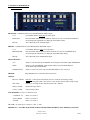
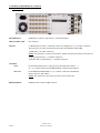
5) TECHNICAL DESCRIPTION
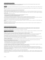
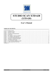
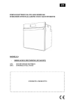
• FRONT PANEL
PROGRAM : CONTROL KEYS of the PROGRAM BUS (MAIN output)
1 to 6
: 6 CONTROL KEYS, displaying one of the inputs.
MAIN LED
: LED turned ON indicates that the ADJUST functions are active on the PROGRAM BUS
selected input (the adjustments are displayed on the MAIN output).
BLACK
: Active BLACK screen on MAIN output.
PRESET : CONTROL KEYS of the PRESET BUS (PREVIEW output)
1 to 6
: 6 CONTROL KEYS to select one of the inputs.
PREVIEW LED
: LED turned ON indicate that the ADJUST functions are active on the PRESET BUS
selected input (the adjustments are displayed on the PREVIEW output).
BLACK
: Active BLACK screen on PREVIEW output.
SWITCHING BUS :
CUT
: Allows to switch seamlessly the PRESET selected input on the MAIN output (PROGRAM).
TAKE
: Allows to switch the PRESET selected input with the selected FADER EFFECT
on the MAIN output (PROGRAM).
FADER EFFECT
: Allows to choose one of the memorized FADER EFFECT (FEA, FEB, FEC)
FREEZE :
Image FREEZE (active when the LED is turned ON)
ADJUST :
RECALL /STORE : RECALL, (a short push on the button), allows to recall the stored image setting.
: STORE, (a long push, LED =ON), allows to store the input format with its image setting.
POS / SIZE
: Position or size image mode (controlled by the H & V buttons)
H POS / H SIZE
: Horizontal image control
V POS / V SIZE
: Vertical image control
LCD WINDOWS : 2 lines / 16 characters LCD
- CONTROL : Please, see section 7.
- EXIT / MENU
: Please, see section 7.
- ENTER
: Please, see section 7.
ON / OFF : AC mains power switch (O = OFF, I = ON)
IMPORTANT : ALL THE ADJUSTMENTS MUST BE REALIZED WITHOUT THE "FREEZE"( LED OFF).
ANALOG WAY
GSW 611R - ED 02/01
PAGE 5
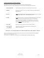
5) TECHNICAL DESCRIPTION (continued)
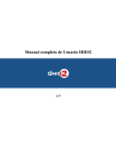
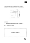
• REAR PANEL
POWER INPUT
: Standard IEC connector (100-240 VAC, 50-60Hz automatic).
HD15 CONNECTOR
: Not connected.
INPUTS
: 6 x RGB inputs (PC, MAC, workstation, scalers, line multiplier) on 3, 4, or 5 BNC connectors.
The input sync type will be automatically detected by the GRAPHIC SWITCHER.
- RGsB (SOG) : on 3 BNC connectors,
NOTE : For SOG input, you must set the input in "USED" SOG position with the LCD menu #1-3
- RGB S (Composite Sync.) : on 4 BNC connectors,
- RGB HV (H & V separated Sync.) : on 5 BNC connectors.
OUTPUTS
MAIN
: For the MAIN display device (video projector, PLASMA, data monitor, ...)
on 3, 4, or 5 BNC connectors and additional HD15 connectors (2nd outputs).
PREVIEW
: For the PREVIEW MONITOR, on 3, 4, or 5 BNC connectors and additional
HD15 connectors (2nd outputs).
NOTE : The output Sync. type can be selected by the LCD menu #2-2
REMOTE RS232
PAGE 6
: Standard remote control on DB9 connector.
ANALOG WAY
GSW 611R - ED 02/01
6) IMAGE ADJUSTMENT & FORMAT MEMORY
The ADJUST Touch Control are dedicated to the control and storage of the image parameters.
Their direct access allows to modify instantaneously and easily the SIZE and POS adjustments of the picture.
• MAIN & PREVIEW
: 2 LEDS indicating which output will be modified by the adjust function.
• FREEZE
: Push button for image freeze (active when LED is ON)Freeze the MAIN and/or the
PREVIEW output.
• RECALL
: A short push on this button allows to recall and display instantaneously the stored image
setting (H POS, H SIZE, V POS, V SIZE which are in memory).
• STORE
: A long push on this button (3 seconds until the STORE LED lights up one time) allows
to memorize the input format and all the image settings of the selected input.
You can memorized in the GRAPHIC SWITCHER™ up to 16 input formats
with their image setting (in the memory, the format and the image settings will
always be associated with one of the 6 inputs).
• POS / SIZE
: Position & size mode, switch which controls both H & V buttons.
• H POS / H SIZE
&
V POS / V SIZE
: 2 digital buttons allow to adjust the Horizontal & Vertical adjustments
(SIZING / POSITIONING)
IMPORTANT : ALL THE ADJUSTMENTS MUST BE REALIZED WITHOUT THE "FREEZE" (LED OFF)
All the correction adjustments on the position & size button will be directly visible on the MAIN and/or the PREVIEW
outputs for one selected input (KEY 1 to 6).
If you memorize a new adjustment, it will always be stored on both the MAIN and the PREVIEW outputs.
ANALOG WAY
GSW 611R - ED 02/01
PAGE 7
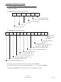
7) LCD MENU & CONTROL
7-1) LCD CONTROL BUTTON
CONTROL button
: Turn this button to adjust (increase, decrease) or select item on the LCD MENUS.
EXIT MENU button
: • From the STATUS MENUS, push on this button to display the CONTROL MENUS
• From the CONTROL MENUS, push on this button to :
- return to the previous menu,
- return to the STATUS MENUS (push several times),
- return without safeguarding the item.
ENTER button
: • From the STATUS MENUS, push on this button to return to the last consulted menu.
• From the CONTROL MENUS, push on this button to confirm a selected item.
NOTE : When entering in the CONTROL MENUS, the LCD windows will display automatically the STATUS MENUS after
60 seconds of inactivity of the front panel buttons.
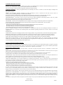
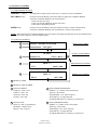
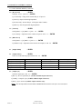
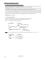
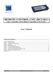
7-2) LCD STATUS MENUS
A
GRAPHIC SWITCHER
B
GSW 611R
MAIN STATUS MENU
OUTPUT
VGA
C
OUTPUT STATUS MENU
SYNC = H & V
PROG = 3
E
XGA
PROGRAM STATUS MENU
48.6K / 60Hz
PRES = 5
F
D
SXGA
PRESET STATUS MENU
64K / 60Hz
A PRODUCT NAME
B PRODUCT PART NUMBER
C OUTPUT FORMAT
• [SXGA] = 1280 x 1024
• [XGA] = 1024 x 768
• [SVGA] = 800 x 600
• [VGA] = 640 x 480
E SELECTED PROGRAM INPUT
• [PROG = 3] = number of the selected input
• [XGA] = input format
• [48.6K/60Hz] = line / frame frequency
• [NO INPUT] = no signal detected
• [CHECK H&V INPUT] = H&V Sync. not detected
D OUTPUT SYNC
• [H & V] = H & V separated Sync.
•[COMP] = composite Sync.
•[SOG] = Sync. on green
F SELECTED PRESET INPUT
• [PRES = 5] = number of the selected input
• [SXGA] = input format
• [64K/60Hz] = line / frame frequency
• [NO INPUT] = no signal detected
• [CHECK H&V INPUT] = H&V Sync. not detected
PAGE 8
ANALOG WAY
GSW 611R - ED 02/01
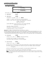
7) LCD MENU & CONTROL (continued)
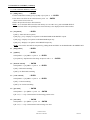
7-3) LCD CONTROL MENUS
Push on EXIT to DISPLAY THE CONTROL MENUS
1 INPUT MENU
2
OUTPUT MENU
3
4
IMAGE MENU
CONTROL MENU
Select menus 1 to 4 with button + ENTER
1 [Input Menu]
+ ENTER
1-1 [Input Status]
+ ENTER
Select [PROG = x] or [PRES = x] with + ENTER
• [PROG = x] = Number of the selected input on the PROGRAM BUS.
• [SYNC = xxxx] = Sync. type
[H+V+] = H & V separated Sync. with polarities.
[COMP] = Composite Sync.
[SOG] = Sync. On Green.
• [XGA 48KHz/60Hz] = Name of the format, line / frame frequency [KHz/Hz],
Interlaced [I] or non interlaced [ ] format.
• [BLACK] = Displays a black screen.
• [NO INPUT] = No signal detected on the "Selected input".
• [CHECK H&V INPUT] = H &V Sync. not detected.
IMPORTANT : WHEN LCD WINDOWS DISPLAYS [CHECK H & V INPUT] :
• PLEASE CHECK THE H.SYNC AND V.SYNC CONNECTIONS (RISK OF INTERVERTION BETWEEN H & V SYNC).
• PLEASE DECREASE THE REFRESH FREQUENCY OR THE RESOLUTION OF THE COMPUTER DISPLAY TO BE
COMPATIBLE WITH THE INPUT RANGE OF THE DEVICE (SEE YOUR COMPUTER VIDEO CARD PARAMETER).
1-2 [Used inputs]
+ ENTER
Select [#1, #2, #3...] with + ENTER , to change the input locking.
• [#1 used] = Input #1 used (KEY 1 is lit ON and enabled).
• [#6 unused] = Input #6 unused (KEY 6 is lit OFF and disabled).
1-3 [Sync On Green]
+ ENTER
Select [#1, #2, #3...] with + ENTER
• [#1 used] = Input #1 is universal and can be connected to a RGsB (SOG) or a RGB S (COMP) or a RGB HV signal.
• [#2 unused] = Input #2 is not compatible with a RGsB (SOG) signal. Only the RGB S (COMP) and the RGB HV
are recognized.
• [all used] = Sets all the inputs universal and compatible with the RGsB, RGB S and RGB HV signal.
• [all unused] = Sets all the inputs compatible only with the RGB S and the RGB HV.
NOTE : In most applications (without any RGsB (SOG) computer sources connected), please always set the SOG input
In the unused position. This avoids any perturbation of the device when you connect a computer which is already
powered ON.
ANALOG WAY
GSW 611R - ED 02/01
PAGE 9
7) LCD MENU & CONTROL (continued)
7-3) LCD CONTROL MENUS (continued)
1-4 [H sync load]
+ ENTER
Select [#1, #2, #3...] with + ENTER
• [#1 75Ω load] = Charge under 75Ω the H Sync. of input #1.
• [#2 Hi-Z] = Input #2 under high impedance.
• [all 75Ω Load] = Sets the H Sync. of all inputs under 75 Ohms.
• [all Hi-Z] = Sets all inputs under high impedance.
1-5 [Contrast]
+ ENTER
Select [PROG = x] or [PRES = x] with + ENTER
• [#3 contrast] = Adjustment of the contrast on input #3 with + ENTER
1-6 [Black Level]
+ ENTER
Select [PROG = x] or [PRES = x] with + ENTER
• [#3 Black level] = Adjustment of the black level on input #3 with + ENTER
2 [Output Menu]
+ ENTER
2-1 [output format]
+ ENTER
Select one of the following output format with + ENTER
FORMAT
[VGA OUTPUT]
[SVGA OUTPUT]
[XGA OUTPUT]
[SXGA OUTPUT]
2-2 [output sync]
RESOLUTION
640 x 480
800 x 600
1024 x 768
1280 x 1024
LINE FREQUENCY
31.5KHz
37.8KHz
48.4KHz
64.0KHz
FRAME FREQUENCY
60Hz
60Hz
60Hz
60Hz
+ ENTER
Select the output Sync. with + ENTER
• [H & V] = H & V separated Sync. (on BNC & HD15 output connectors).
• [COMP] = Composite Sync. (on BNC & HD15 output connectors).
• [SOG] = Sync. On Green (on BNC output connector only).
NOTE : The 2nd output HD15 female MAIN and PREVIEW do not deliver the Sync. On Green (SOG).
PAGE 10
ANALOG WAY
GSW 611R - ED 02/01
7) LCD MENU & CONTROL (continued)
7-3) LCD CONTROL MENUS (continued)
2-3 [fading effect]
+ ENTER
• Select a Fader Effect memory [FEA] or [FEB] or [FEC] with + ENTER
• Now choose one effect for the selected memory with + ENTER
(Please see the list in section 12).
• Renew the operation for the 2 other memories.
NOTE : To see the Fader Effect stored in each memory (FEA or FEB or FEC), push on FADER EFFECT.
The Fader Effect corresponding to the selected memory is also displayed on the LCD windows.
2-4 [test pattern]
+ ENTER
• [OFF] = Turns OFF the test pattern.
• [ON prog + pres] = Displays a test pattern on the PROGRAM and the PRESET outputs.
• [ON prog] = Displays a test pattern on the PROGRAM output only.
• [ON pres] = Displays a test pattern on the PRESET output only.
NOTE : You can also turn OFF the test pattern by pushing the BLACK KEY on the PROGRAM or the PRESET BUS.
3 [Image Menu]
+ ENTER
3-1 [optimize]
+ ENTER
Select [PROG = x] or [PRES = x] with + ENTER
• [#3 optimize] = Optimization of the image on input #3 with + ENTER
3-2 [horizont. smooth]
+ ENTER
Select [PROG = x] or [PRES = x] with + ENTER
• [ON] = Horizontal smoothing.
• [OFF] = No Horizontal smoothing.
3-3 [vertic. smooth]
+ ENTER
Select [PROG = x] or [PRES = x] with + ENTER
• [ON] = Vertical smoothing.
• [OFF] = No Vertical smoothing.
3-4 [pos status]
+ ENTER
Select [PROG = x] or [PRES = x] with + ENTER
• [H = 127, V = 127] = Horizontal and Vertical image position value.
3-5 [size status]
+ ENTER
Select [PROG = x] or [PRES = x] with + ENTER
• [H = 127, V = 127] = Horizontal and Vertical image size value.
ANALOG WAY
GSW 611R - ED 02/01
PAGE 11
7) LCD MENU & CONTROL (continued)
7-3) LCD CONTROL MENUS (continued)
4 [Control Menu]
4-1 [languages]
4-2 [key locking]
+ ENTER
Select which locking function you need with + ENTER
• [all unlock] = Front panel unlocked.
• [all lock] = Front panel locked with a LCD message (how to unlock).
• [adj + frz lock] = Adjust + Freeze functions locked with a LCD message (how to unlock).
NOTE : To unlocked the front panel, push simultaneously on ENTER and EXIT
4-3 [cross fad/cut]
+ ENTER
• [NO] = When switching with CUT or TAKE, the PRESET input is displayed on the PROGRAM and PRESET outputs.
• [YES] = When switching with CUT or TAKE, the PROGRAM input is permuted with the PRESET input.
4-4 [follow mode]
+ ENTER
• [NO] = The output frame rate is 60Hz.
• [YES] = The output frame rate is identical to the frame rate of the INPUT 1 of the GRAPHIC SWITCHER.
NOTE : The INPUT 1 compatibility range in FOLLOW MODE is 50Hz frame or 60Hz frame only.
4-5 [erase all mem]
+ ENTER
• [NO] = Do not erase the input formats and settings memorized.
• [YES] = Erase all the following memorized information :
- Input formats parameters,
- Position & Size image settings,
- Optimization adjustment.
4-6 [version]
+ ENTER
Status of the internal firmware.
• xxxx xxxx xxxx
4-7 [default value]
+ ENTER
• [NO] = No adjustments and settings are modified.
• [YES] = Clear the following adjustments and set them to the factory value.
1-2
1-3
1-4
1-5
1-6
2-1
2-2
2-3
2-4
3-2
3-3
4-1
4-3
4-4
PAGE 12
Used Inputs
Sync On Green
H Sync Load
Contrast
Black Level
Output Format
Output Sync
Fading Effect
Test Pattern
Horizont. Smooth
Vertic. Smooth
Languages
Cross Fad / Cut
Follow mode
= All input KEY are enable
= All input do not recognize the RGsB (SOG) signal
= All H Sync. BNC inputs are Hi-Z
=0
=0
= XGA
= H & V separated
= FEA = fading 3s, FEB = title 5s, FEC = shad + title h
= OFF
= OFF
= OFF
= English
= Yes
= No
ANALOG WAY
GSW 611R - ED 02/01
8) OPERATING MODE
8-1) INSTALLATION (Please see section 3 & 4).
8-2) ADJUSTMENTS
• DEFAULT VALUE
Before a new adjustment, it is possible to reset the GSW 611R to its default value (factory setting)
(Please, see section 7, menu # 4-7).
• INPUT KEY
Before operating, use the LCD menu # 1-2 to disable the input KEY (1 to 6) which will be unused.
Luminous code for KEY • Light OFF (for disable KEY)
• Low light (no selected KEY)
• Height light (selected KEY)
• Blinking light (operation in progress)
• OUTPUT SETTING
- Select your output format resolution and Sync. type (Please, see section 7, menu # 2-1 & menu # 2-2).
NOTE : The SYNC ON GREEN (SOG) is available only on the BNC outputs.
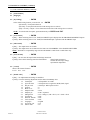
• DISPLAY ADJUSTMENT (PROJECTOR)
- Set the test pattern on [ON prog + pres] (LCD menu # 2-4).
Four corner marks appear on the MAIN and the PREVIEW displayed images.
- Use the 4 corner marks to fill in the full screen your displayed image with the display device parameters.
ADJUST DIRECTLY THE DISPLAY DEVICE PARAMETERS (PROJECTOR...)
- Renew the same process to adjust your preview display.
Now both the MAIN and the PREVIEW displays are identically adjusted (Position & Size of the picture) ; you
have now the possibility to adjust a new input source directly on the PREVIEW monitor, even if you
didn’t have a direct visual entrance on the MAIN display.
• INPUT IMAGE ADJUSTMENT
- Select one input on the PROGRAM or the PRESET BUS and make your Position and Size adjustments
with the ADJUST functions of the GRAPHIC SWITCHER.
- Push 3 seconds the STORE button (LED = ON) to memorize the adjustments.
Now your input format and its image setting are memorized for both the MAIN and the PREVIEW outputs.
- Renew the operation for each input used.
- To turn OFF the test pattern, please see LCD menu # 2-4.
NOTE : If you are in live display, you can also make corrections on the PREVIEW output only, without
disturbing the main output picture (select [ON pres] with LCD menu # 2-4)
NOTE : With a specific pattern image, you can also optimize the image (Please, see LCD menu # 3-1).
ANALOG WAY
GSW 611R - ED 02/01
PAGE 13
8) OPERATING MODE (continued)
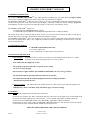
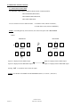
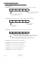
8-3) SWITCHING OPERATION
The GRAPHIC SWITCHER is equipped with three BUS of luminous KEYS :
• The PROGRAM (MAIN) BUS,
• The PRESET (PREVIEW) BUS,
• The SWITCHING BUS.
You can switch between two different modes : - In Seamless mode (with the CUT KEY),
- In Fader Effect mode (with the TAKE KEY),
NOTE : If switching directly on the same bus, the switch will operate with a Fast to black.
• CUT
PROGRAM
1
2
PROGRAM
+
3
PRESET
1
CUT
2
3
PRESET
(Seamless)
1
2
3
1
*
2
3
Input #1 is displayed on the MAIN output
Input #2 is displayed on the MAIN output
Input #2 is displayed on the PREVIEW output
Input #1 is displayed on the PREVIEW output
Pushing CUT a second time will set back the output.
NOTE : The CROSS CUT MODE CAN BE MODIFIED (Please, see section 7, menu #4-3).
PAGE 14
ANALOG WAY
GSW 611R - ED 02/01
8) OPERATING MODE (continued)
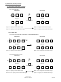
8-3) SWITCHING OPERATION (continued)
• CUT (NOT CROSS)
PROGRAM
1
2
PROGRAM
+
3
PRESET
1
CUT
2
3
PRESET
(Seamless CUT)
1
2
3
1
*
2
3
Input #1 is displayed on the MAIN output
Input #2 is displayed on the MAIN output
Input #2 is displayed on the PREVIEW output
Input #2 is displayed on the PREVIEW output
• CUT TO BLACK
- You can directly PUSH THE BLACK KEY OF THE PROGRAM BUS
PROGRAM
1
2
3 ...
PROGRAM
B
(
1
PRESET
2
3 ... B
PRESET
(Seamless)
1
2
3 ...
B
1
Input #1 is displayed on the MAIN output
2
3 ... B
Black screen is displayed on the MAIN output
- You can also proceed as a CUT
PROGRAM
1
2
3 ...
PROGRAM
+
B
PRESET
1
CUT
2
3 ... B
PRESET
(Seamless CUT)
1
2
3 ...
B
1
2
3 ... B
Input #1 is displayed on the MAIN output
Black screen is displayed on the MAIN output
Black screen is displayed on the PREVIEW output
Input #1 is displayed on the PREVIEW output
ANALOG WAY
GSW 611R - ED 02/01
PAGE 15
8) OPERATING MODE (continued)
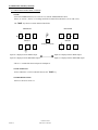
8-3) SWITCHING OPERATION (continued)
• FADE
- Select the FADER EFFECT (FEA or FEB or FEC) with the FADER EFFECT KEY.
Please, see section 7, menu # 2-3 to change the Effect in Fader Effect Memories (FEA or FEB or FEC).
The TAKE key allows to switch with the Fader Effect.
PROGRAM
1
2
PROGRAM
+
3
PRESET
1
2
3
PRESET
TAKE
(Fading 3 seconds)
1
2
3
1
*
2
3
Input #1 is displayed on the MAIN output
Input #2 is displayed on the MAIN output
Input #2 is displayed on the PREVIEW output
Input #1 is displayed on the PREVIEW output
- This is a 3 seconds Fade between Input #1 and Input #2.
• FADE TO BLACK
Process identical to a CUT TO BLACK but uses the TAKE key.
• FADER EFFECT LIST
Please see the list in section 12.
PAGE 16
ANALOG WAY
GSW 611R - ED 02/01
9) TECHNICAL SPECIFICATION
• DISPLAY
THE RECOGNITION OF THE DIFFERENT DISPLAY MODES IS AUTOMATIC AND IMMEDIATE
Scanning
: AUTO SCAN MODE.
Colors
: 16 Millions (3 RGB Memory Plane).
Image Freeze
: Synchronized in frame (Freeze).
• INPUTS
Software Compatibility
: All software compatible.
Hardware Compatibility
: Line frequency : From 31.5KHz to 130KHz.
: Resolutions : From 640 x 480 to 1600 x 1280.
: Sync : H & V, COMP, SOG.
Levels
: R, V, B = 3 x 0.7Vp/p.
: H & V sync = TTL.
: Composite sync = TTL and 0.3Vp/p.
: SOG (Sync On Green) = 0.3Vp/p.
Impedance
: 75 Ohms (R, V, B) ; Hi-Z or 75 Ohms (H & C Sync).
• OUTPUTS (MAIN & PREVIEW)
Levels
: R, G, B = 3 x 0.7Vp/p.
: H & V Sync = TTL.
: Composite Sync = TTL.
: SOG = 0.3Vp/p under 75 Ohms.
Impedance
: 75 Ohms for (R, G, B, S).
Format
: The GRAPHIC SWITCHER allows to choose your output format (LCD Menu # 2-1) between:
- SXGA
1280 x 1024
64.0KHz / 60Hz
- XGA
1024 x 768
48.4KHz / 60Hz
- SVGA
800 x 600
37.8KHz / 60Hz
- VGA
640 x 480
31.5KHz / 60Hz.
• REMOTE PORT
Level
: RS 232.
Data Rate
: 9600 Bauds, 8 bits data, 1 bit stop, No parity bit.
• ENVIRONMENTAL
Power Supply
: Internal CE / UL / CSA / IEC 950 (130W).
: Input : 100VAC to 240VAC ; 50-60Hz ; I = 3A Max.
Temperature
: Storage : -25 °C to +85 °C.
Hygrometry
: 10% to 80% (without condensation).
Dimension
: W480 x D340 x H133mm / 19”W x 13.4”D x 5.2”H.
: (Compatible with a 19” Standard, Height = 3 units).
Weight
: 6.5Kg / 14.3Lbs.
ANALOG WAY
GSW 611R - ED 02/01
PAGE 17
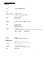
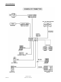
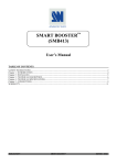
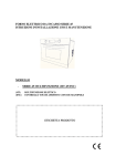
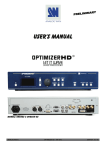
10) CONNECTIONS
PAGE 18
ANALOG WAY
GSW 611R - ED 02/01
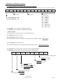
11) REMOTE CONTROL RS 232
The RS-232 communication interface built in your GRAPHIC SWITCHER, allows it to be controlled from a host system.
The RS-232 connector pin-out and software installation are shown below.
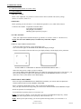
11-1) CONNECTION
• CONNECTING THE RS-232 (cable not supplied)
To connect the GRAPHIC SWITCHER to a controlling device, connect a RS-232 straight cable (DB9 pins female / DB9
pins male) from the host serial port to the GRAPHIC SWITCHER connector labeled REMOTE RS-232.
• PIN-OUT
Pin #
2
3
5
Functions
TRANSMIT DATA (Tx)
RECEIVE DATA (Rx)
GROUND (Gnd)
DB 9 female connector
(Rear panel of GRAPHIC SWITCHER)
• SPEED TRANSMISSION
9600 bauds, 8 data bits, 1 stop bit, No parity.
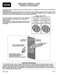
11-2) "GRAPHIC SWITCHER CONTROL PANEL" SOFTWARE
Your GRAPHIC SWITCHER is shipped with a compatible WINDOWS 95/98/2000 "GRAPHIC SWITCHER
CONTROL PANEL" (3"1/2 disk).This software allows you to make adjustments and controls by a simple mouse click.
• INSTALLING ON PC :
c Connect the serial port of the computer to the RS-232 remote connector of the GRAPHIC SWITCHER,
d Switch ON your computer and wait for WINDOWS to completely start,
e Insert the disk into the floppy drive,
f In the WINDOWS PROGRAM MANAGER menu, click on RUN,
g Choose the disk drive and click on SETUP.EXE. (ex : A:\SETUP.EXE if disk 3"1/2 is drive A),
h Follow the WINDOWS installation instructions, WINDOWS will create a C:\Program files\Analog Way\GSW 611.
ANALOG WAY
GSW 611R - ED 02/01
PAGE 19
11) REMOTE CONTROL RS 232 (continued)
11-2) "GRAPHIC SWITCHER CONTROL PANEL" SOFTWARE (continued)
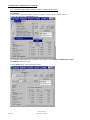
• STARTING
c Click on the program files GSW 611 in start –program - ANALOG WAY to run the software,
d Select the serial port in CONTROLS menu,
The GRAPHIC SWITCHER is now connected to the computer ; make a RESET TO DEFAULT VALUE
(CONTROLS menu) if necessary.
d In the INPUT menu, select all the inputs setting.
PAGE 20
ANALOG WAY
GSW 611R - ED 02/01
11) REMOTE CONTROL RS 232 (continued)
11-2) "GRAPHIC SWITCHER CONTROL PANEL" SOFTWARE (continued)
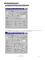
f In the OUTPUT menu, select the output format and the output sync type
g In the IMAGE menu, make the adjustments for all of your inputs. The adjustments are active on the last selected input.
NOTE : For position & size image adjustments, you can use the test pattern in output menu.
ANALOG WAY
GSW 611R - ED 02/01
PAGE 21
11) REMOTE CONTROL RS 232 (continued)
11-3) HOST / GRAPHIC SWITCHER COMMUNICATION
If you need to use your own control software program with a PC, MAC or WORKSTATION by a RS-232 port, the
GRAPHIC SWITCHER allows to communicate by simple transmit or receive ASCII code.
The GRAPHIC SWITCHER treats any character that it received on the RS-232 as a possible command but accepts only
legal commands. There are no codes to say that a command is coming, or that a command is ended.
A command could be a single character typed on a keyboard and does not required any special characters before or after
(it is not necessary to press "ENTER" from the keyboard). Simple commands could be from a PC or any other controlling
device. When the GRAPHIC SWITCHER receives a valid command, it will execute the command and send a response
back to the host device. If the command is invalid, an error response will be returned to the host. All responses to the host
end with a carriage return and a line feed (CR / LF) signaling the end of the response character string.
• PROTOCOL : Simple character
• CONTROLS STRUCTURE
Controls are usually composed of a numeric value followed by the letter of the command.
The letter used without numeric value returns the current setting of the command.
Please see "COMMANDS AND RESPONSES TABLE"
( PARAMETER )
< COMMAND >
1 character (usually a letter)
Without parameter :
Read back the current value
ex : H ⇒ HPOSg10 ↵
With a numerical parameter :
Set a new value
ex : 80H ⇒ HPOSg80 ↵
NOTE : The { or } parameter are active only on image positioning and sizing commands (H, V, W, S, h, v, w, s)
( PARAMETER )
< COMMAND >
Character { : Increase current value by 1
ex : { H ⇒ HPOSg81 ↵
Character } : Decrease current value by 1
ex : } H ⇒ HPOSg79 ↵
PAGE 22
ANALOG WAY
GSW 611R - ED 02/01
11) REMOTE CONTROL RS 232 (continued)
11-3) HOST / GRAPHIC SWITCHER COMMUNICATION (continued)
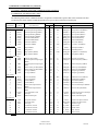
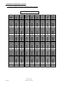
• COMMANDS AND RESPONSES TABLE
The following table resumes commands which are recognized as valid and the responses that will be returned to the host
(on RS-232 port). Error response format and possible error type are shown at the bottom on this page.
ASCII
COMMAND
RESPONSE
TO HOST
COMMAND
DESCRIPTION
VALUE
EXAMPLE
MIN MAX COMMAND RESPONSE
ACTION EXPLANATION
Image positioning and sizing :
H
HPOSg
h
HPOSs
V
VPOSg
v
VPOSs
W
HSIZg
w
HSIZs
S
VSIZg
s
VSIZs
Output Controls
E
TSO
F
FAD
O
OPTIg
o
OPTIs
Input Status (Read only)
U
UNIT
D
DHIg
d
DHIs
L
l
T
t
Input controls
N
n
G
g
C
GRTg
GRTs
TSYg
TSYs
BLVg
BLVs
GAINg
GAINs
CHANg
c
CHANs
P
I
i
Miscellaneous
Y
Z
?
R
M
X
K
LOAD
SELI
SOGI
CDE
DTC
DEV
R_
M_
L_
K_
Horizontal positioning (PROG)
Horizontal positioning (PRES)
Vertical positioning (PROG)
Vertical positioning (PRES)
Horizontal width (PROG)
Horizontal width (PRES)
Vertical size (PROG)
Vertical size (PRES)
0
0
0
0
0
0
0
0
255
255
255
255
255
255
255
255
20H
h
V
v
W
w
S
150s
HPOSg20
HPOSs73
VPOSg85
VPOSs128
HSIZg110
HSIZs100
VSIZg100
VSIZs150
Set H position to 20 (PROG)
Read H position (PRES)
Read V position (PROG)
Read V position (PRES)
Read H width (PROG)
Read H width (PRES)
Read V size (PROG)
Set V size to 150 (PRES)
Output standard
Fading effects
Image optimize (PROG)
Image optimize (PRES)
0
0
0
0
4095
16383
255
255
E
F
120O
o
TSO33
FAD10325
OPTIg120
OPTIs80
Read Output standard
Read Fading Effects
Set optimize to 120 (PROG)
Read optimize (PRES)
Measures unity in KHz
Horizontal period of input signal
(PROG)
Horizontal period of input signal
(PRES)
Number of line per field (PROG)
Number of line per field (PRES)
Sync Type (PROG)
Sync Type (PRES)
0
0
65535
65535
U
D
0
65535
d
DHIs564
Read line frequency (PRES)
0
0
0
0
65535
65535
255
255
L
l
T
t
GRTg600
GRTs768
TSYg113
TSYs125
Read line per field (PROG)
Read line per field (PRES)
Read Sync type (PROG)
Read Sync type (PRES)
Black level (PROG)
Black level (PRES)
Contrast (PROG)
Contrast (PRES)
Number of the input channel
(PROG)
Number of the input channel
(PRES)
H sync load under 75 Ω
Used input
Valid the SOG inputs
0
0
0
0
1
255
255
255
255
6
85N
n
G
g
C
BLVg85
BLVs110
GAINg20
GAINs30
CHANg2
Set Black level to 85 (PROG)
Read Black level (PRES)
Read contrast (PROG)
Read contrast (PRES)
Read # of selected input (PROG)
1
6
3c
CHANs3
Select the 3rd input (PRES)
0
0
0
63
63
63
P
I
i
LOAD1
SELI3
SOGI35
Read the Hsync load (75 Ω) input
Read the used input
Read the valid SOG inputs
Front panel selection
Front panel status
Device type
"R" Firmware Version
"M" Firmware Version
"L" Firmware Version
"K" Firmware Version
0
0
0
0
0
0
0
63
65535
65535
65535
65535
65535
65535
Y
Z
?
R
M
X
K
CDE12
DTC13242
DEV3
R_57427
M_13316
L_18915
K_12348
UNIT17734 Read unity of measures
DHIg564 Read line frequency (PROG)
Read the Front panel selection
Read the Front panel status
Read device type
Read R version
Read M version
Read L version
Read K version
NOTE : PROG = PROGRAM BUS, PRES = PRESET BUS.
ANALOG WAY
GSW 611R - ED 02/01
PAGE 23
11) REMOTE CONTROL RS 232 (continued)
11-3) HOST / GRAPHIC SWITCHER COMMUNICATION (continued)
• ERROR RESPONSES
When the GRAPHIC SWITCHER receives from the host an invalid command or value, it returns an error response
E10 ↵
invalid command (See "COMMAND" column)
E13 ↵
invalid value (See "VALUE" column)
• COMMANDS DESCRIPTION
Values sent or received are in decimal.
Depending on command letter, value can be used as linear control (ex : 255w to set Horiz Zoom at maximum) or as set
of bits (ex : T command with multiple controls).
In this case, value must be converted in binary base to understand every bit action.
Example :
Host receives message TSYg71
Decimal value 71 = binary value 0100 0111
71 = (128 x 0) + (64 x 1) + (32 x 0) + (16 x 0) + (8 x 0) + (4 x 1) + (2 x 1) + (1 x 1)
bit 7 = 0 means input signal compatible
bit 6 = 1 means non interlaced signal
bits 5, 4 and 3 = 000 mean H&V separated sync.
bit 2 = 1 means positive V sync.
bit 1 = 1 means positive H sync.
bit 0 = 1 means input signal detected
c IMAGE POSITIONING AND SIZING
• H, h, V, v commands are used to control Position of output image.
• W, w, S, s commands are used to control Size of output image.
Commands can be used in two different ways :
- Command letter alone to read present value,
- ASCII numbers followed by command letter to set a value.
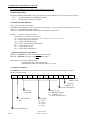
d OUTPUT CONTROLS
• E command is used to control output format, output sync, horizontal and vertical smoothing, test pattern,
CROSS CUT/FAD setting :
bit 11
(2048)
bit 10
(1024)
bit 9
(512)
bit 8
(256)
bit 7
(128)
bit 6
(64)
bit 5
(32)
bit 4
(16)
bit 3
(8)
bit 2
(4)
bit 1
(2)
bit 0
(1)
1 = Test pattern
on PROG = ON
1 = Test pattern
on PRES = ON
Reserved to manufacturer
Reserved to
manufacturer
1 = Cross FAD/CUT
= YES
Output sync. type
00 = H&V separated sync.
01 = Composite sync.
10 = Sync. On Green (SOG)
Output format
00 = SXGA
01 = XGA
10 = SVGA
11 = VGA
Reserved to manufacturer
PAGE 24
ANALOG WAY
GSW 611R - ED 02/01
11) REMOTE CONTROL RS 232 (continued)
11-3) HOST / GRAPHIC SWITCHER COMMUNICATION (continued)
• F command is used to select the fading effect (FEA, FEB, FEC) and choose an effect for FEA, FEB, and FEC memories.
bit 13
(8192)
bit 12
(4096)
bit 11
(2048)
FEC
bit 10
(1024)
bit 9
(512)
bit 8
(256)
bit 7
(128)
memory
FEB
bit 6
(64)
bit 5
(32)
bit 4
(16)
bit 3
(8)
memory
bit 2
(4)
bit 1
(2)
bit 0
(1)
FEA
memory
0000 = Fading 0.5s
0001 = Fading 1s
0010 = Fading 2s
0011 = Fading 3s
0100 = Fading 4s
0101 = Fading 5s
0110 = Title 5s
0111 = Holding title
1000 = Shad + title 5s
1001 = Shad + h title
00 = Active fading effect = FEA
01 = Active fading effect = FEB
10 = Active fading effect = FEC
• O command is used to optimize the MAIN output image.
• o command is used to optimize the PREVIEW output image .
e INPUT STATUS
This control family is read only. They can’t be preceded with value.
• U command returns the UNIT value.
•D & d commands return the DHI value.
The following formula allows to calculate the computer input line frequency (in KHz) : UNIT VALUE
DHI VALUE
• L & l commands return the GRT value.
The following formula allows to calculate the input frame frequency (in Hz) : Input line frequency (Hz)
GRT Value
• T command returns the signal status of the input selected on PROGRAM BUS.
• t command returns the signal status of the input selected on PRESET BUS.
bit 7
(128)
bit 6
(64)
bit 5
(32)
bit 4
(16)
bit 3
(8)
bit 2
(4)
bit 1
(2)
bit 0
(1)
1 = Presence of input signal
0 = Negative H sync. input
1 = Positive H sync. input
0 = Negative V sync. input
1 = Positive V sync. input
xx0 = Separated H&V sync.
x01 = Sync. On Green (SOG)
011 = 0.3V Analog composite sync.
111 = TTL composite sync.
1 = Non interlaced input signal
1 = Input signal is out of range
ANALOG WAY
GSW 611R - ED 02/01
PAGE 25
11) REMOTE CONTROL RS 232 (continued)
11-3) HOST / GRAPHIC SWITCHER COMMUNICATION (continued)
f INPUT CONTROLS
• P command allows to load under 75 Ohms or high impedance the H sync. BNC connector of each input.
bit 5
(32)
bit 4
(16)
bit 3
(8)
bit 2
(4)
bit 1
(2)
bit 0
(1)
1 = H sync. of input #1 = 75Ω impedance
0 = H sync. of input #1 = Hi-Z
1 = H sync. of input #6 = 75Ω impedance
0 = H sync. of input #6 = Hi-Z
• I command allows to enable or disable each input and the corresponding front panel luminous key :
bit 5
(32)
bit 4
(16)
bit 3
(8)
bit 2
(4)
bit 1
(2)
bit 0
(1)
0 = Input #1 unused
1 = Input #1 used
0 = Input #6 unused
1 = Input #6 used
• i command allows to enable or disable the SOG (Sync. On Green) detection of each input :
bit 5
(32)
bit 4
(16)
bit 3
(8)
bit 2
(4)
bit 1
(2)
bit 0
(1)
0 = Input #5 is not compatible with SOG signal (only H & V separate & C.sync.)
1 = Input #5 is compatible with all sync. signal (H & V separate, C. sync. & SOG)
0 = Input #6 is not compatible with SOG signal (only H & V separate & C.sync.)
1 = Input #6 is compatible with all sync. signal (H & V separate, C. sync. & SOG)
• N command is used to control the black level of the MAIN output.
• n command is used to control the black level of the PREVIEW output.
• G command is used to control the contrast of the MAIN output.
• g command is used to control the contrast of the PREVIEW output.
• C command is used to select an input on the PROGRAM bus.
• c command is used to select an input on the PRESET bus.
PAGE 26
ANALOG WAY
GSW 611R - ED 02/01
11) REMOTE CONTROL RS 232 (continued)
11-3) HOST / GRAPHIC SWITCHER COMMUNICATION (continued)
g MISCELLANEOUS
•Y command controls actions from FRONT PANEL.
bit 5
(32)
bit 4
(16)
bit 3
(8)
bit 2
(4)
bit 1
(2)
bit 0
(1)
1 = Store the image setting
1 = RECALL the stored image setting
1 = Erase all image setting
1 = CUT action
1 = TAKE action
1 = Set the default value
• Z command controls the FRONT PANEL.
bit 11
(2048)
bit 10
(1024)
bit 9
(512)
bit 8
(256)
bit 7
(128)
bit 6
(64)
bit 5
(32)
bit 4
(16)
bit 3
(8)
bit 2
(4)
bit 1
(2)
bit 0
(1)
0 = Last selected input
on PRESET
1 = Last selected input
on PROGRAM
1 = Last action made bythe
front panel key
00 = Front panel unlocked
01 = Front panel locked with help message
1X = ADJUST + FREEZE locked
1 = Display black screen on MAIN output*
1 = Display black screen on PREVIEW output*
1 = Freeze the MAIN output
1 = Freeze the PREVIEW output
1 = Horizontal smoothing on PROG = ON
1 = Horizontal smoothing on PRESET = ON
1 = Vertical smoothing on PROG = ON
1 = Vertical smoothing on PRESET = ON
*Please do not set the bit #4 and bit #5 directly to 0 value with the Z command.
To switch OFF the black screen, you must select another input (1, 2, 3, ..., 6) with the C command.
• ?, R, M, L, K, commands are the status of the device’s internal firmware (read only).
ANALOG WAY
GSW 611R - ED 02/01
PAGE 27
11) REMOTE CONTROL RS 232 (continued)
11-3) HOST / GRAPHIC SWITCHER COMMUNICATION (continued)
ASCII / HEX / DEC TABLE
PAGE 28
ASCII
HEX
DEC
ASCII
HEX
DEC
ASCII
HEX
DEC
space
!
"
#
$
%
&
’
(
)
*
+
,
.
/
0
1
2
3
4
5
6
7
8
9
:
;
<
=
>
?
20
21
22
23
24
25
26
27
28
29
2A
2B
2C
2D
2E
2F
30
31
32
33
34
35
36
37
38
39
3A
3B
3C
3D
3E
3F
32
33
34
35
36
37
38
39
40
41
42
43
44
45
46
47
48
49
50
51
52
53
54
55
56
57
58
59
60
61
62
63
@
A
B
C
D
E
F
G
H
I
J
K
L
M
N
O
P
Q
R
S
T
U
V
W
X
Y
Z
[
\
]
^
_
40
41
42
43
44
45
46
47
48
49
4A
4B
4C
4D
4E
4F
50
51
52
53
54
55
56
57
58
59
5A
5B
5C
5D
5E
5F
64
65
66
67
68
69
70
71
72
73
74
75
76
77
78
79
80
81
82
83
84
85
86
87
88
89
90
91
92
93
94
95
`
a
b
c
d
e
f
g
h
i
j
k
l
m
n
o
p
q
r
s
t
u
v
w
x
y
z
{
|
}
~
DEL
60
61
62
63
64
65
66
67
68
69
6A
6B
6C
6D
6E
6F
70
71
72
73
74
75
76
77
78
79
7A
7B
7C
7D
7E
7F
96
97
98
99
100
101
102
103
104
105
106
107
108
109
110
111
112
113
114
115
116
117
118
119
120
121
122
123
124
125
126
127
ANALOG WAY
GSW 611R - ED 02/01
12) FADER EFFECT LIST
All the following effects are available in le LCD menu # 2-3.
1 Fading 0.5s
The Preview image fades in with the Main image in 0.5 second.
2 Fading 1s
The Preview image fades in with the Main image in 1 second.
3 Fading 2s
The Preview image fades in with the Main image in 2 seconds.
4 Fading 3s
The Preview image fades in with the Main image in 3 seconds.
5 Fading 4s
The Preview image fades in with the Main image in 4 seconds.
6 Fading 5s
The Preview image fades in with the Main image in 5 seconds.
7 Title 5s
• The PROGRAM BUS is displaying the Main image
• Select on PRESET BUS a black image with a white title
(made the title with a Text or Drawn standard software).
• Push TAKE : The title is inserted on the main image.
• The title disappears automatically after 5 seconds.
8 Holding Tittle
Same function as Title 5s.
But you must push again TAKE to remove the title.
9 Shad + Tittle 5s
Same function as Title 5s, excepted that a shadow bar appears at the bottom
of the image.
10 Shad + Tittle h
Same function as Shad + Title 5s. But you must push again TAKE to
remove the shadow and the title.
NOTE : The Shad + Tittle h and the Shad + Tittle 5s effects are not available when the test pattern is active.
ANALOG WAY
GSW 611R - ED 02/01
PAGE 29
WARRANTY
Analog Way warrants the product against any defects in materials and workmanship for a period of three years from the
date of purchase (back to the factory).
In the event of any malfunction during the warranty period, Analog Way will, at its option, repair or replace the defective
units, including free materials and labor.
This warranty does not apply if the product has been :
- improperly installed or abused,
- handled with improper care,
- used or stocked in abnormal conditions,
- modified, opened,
- damaged by fire, war, or Natural disasters (Acts of God).
In no way shall Analog Way be responsible for direct or indirect loss of profit or consequential damages resulting from any
defect in this product.
In case of any problem, get the serial number of the unit, a description of the problem, and then call your authorized dealer.
PAGE 30
ANALOG WAY
GSW 611R - ED 02/01