1
026-1722 Rev 03-JUN-20
MultiFlex PAK Compressor/
Condenser Control Board
User’s Guide
3240 Town Point Drive NW Suite 100
Kennesaw, GA 30144, USA
Phone: 770-425-2724
Fax: 770-425-9319
ALL RIGHTS RESERVED.
The information contained in this manual has been carefully checked and is believed to be accurate. However, Computer Process Controls, Inc. assumes no responsibility for any inaccuracies that may be contained herein. In no event will
Computer Process Controls, Inc. be liable for any direct, indirect, special, incidental, or consequential damages resulting
from any defect or omission in this manual, even if advised of the possibility of such damages. In the interest of continued
product development, Computer Process Controls, Inc. reserves the right to make improvements to this manual, and the
products described herein, at any time without notice or obligation.
READ ALL INSTRUCTIONS CAREFULLY
If the equipment is not used in the manner specified by the manufacturer, the protection provided
by the equipment may be impaired.
SAVE THIS INSTRUCTION MANUAL
This instruction manual contains important operating instructions for the MultiFlex PAK boards.
Table of Contents
1 OVERVIEW OF THE MULTIFLEX PRODUCT LINE .......................................................................................... 1
1.1. MULTIFLEX PAK ......................................................................................................................................................... 1
1.1.1. Hardware .............................................................................................................................................................. 1
2 MOUNTING AND POWERING ................................................................................................................................. 2
2.1. SNAP-TRACK INSTALLATION ........................................................................................................................................
2.2. THE PLUG-IN OUTPUT BOARD .....................................................................................................................................
2.3. POWERING THE MULTIFLEX .........................................................................................................................................
2.3.1. Choosing Transformer Sizes .................................................................................................................................
2.3.2. MultiFlex Combination Input/Output Board Power Wiring.................................................................................
2
3
3
4
4
2.3.2.1. New-Style MultiFlex Combination I/O Boards (with Isolated Power Supply).................................................................. 4
2.3.2.2. Old-Style MultiFlex Combination I/O Boards (No Isolated Power Supply)...................................................................... 5
2.3.3. Wire Types and Maximum Distances.................................................................................................................... 6
3 THE I/O NETWORK .................................................................................................................................................... 7
3.1. WIRING TYPES .............................................................................................................................................................. 7
3.2. DAISY CHAINS ............................................................................................................................................................. 7
3.2.1. Network ID Numbers ............................................................................................................................................ 7
3.2.1.1. Numbering the MultiFlex PAK .......................................................................................................................................... 7
3.2.2. Setting the Baud Rate............................................................................................................................................ 8
3.2.3. Setting the Terminating Resistance Jumpers ........................................................................................................ 8
4 I/O BOARD INPUT AND OUTPUT SETUP.............................................................................................................. 9
4.1. THE INPUTS................................................................................................................................................................... 9
4.1.1. Input Types Supported by the MultiFlex PAK ...................................................................................................... 9
4.1.2. The PAK Default Input Assignments................................................................................................................... 10
4.1.3. Connecting Sensors to Input Boards................................................................................................................... 10
4.1.3.1. Wiring ............................................................................................................................................................................... 10
4.1.3.2. Sensor Wiring Types ........................................................................................................................................................ 10
4.1.3.3. Input Type Dip Switches .................................................................................................................................................. 10
4.1.4. Power Connection............................................................................................................................................... 11
4.1.4.1. Current Ratings for On-Board Power Sources ................................................................................................................. 11
4.1.4.2. Powering Sensors Requiring 24VAC Off the Power Transformer................................................................................... 11
4.1.5. Sensor Types for MultiFlex Input Points ............................................................................................................
4.2. THE RELAY OUTPUTS .................................................................................................................................................
4.2.1. Output Types Supported by the MultiFlex PAK..................................................................................................
4.2.2. The PAK Default Output Assignments ................................................................................................................
4.2.3. Wiring..................................................................................................................................................................
4.2.4. Output Fail-Safe Dip Switches............................................................................................................................
4.2.5. Relay Output Ratings and Fuse Protection.........................................................................................................
4.3. THE ANALOG AND DIGITAL OUTPUTS .......................................................................................................................
4.3.1. Digital/Analog Output Types Supported by the MultiFlex PAK.........................................................................
4.3.2. The PAK Default Analog/Digital Output Assignments .......................................................................................
11
12
12
12
12
12
13
14
14
14
5 BOARD STATUS LEDS ............................................................................................................................................. 15
5.1.
5.2.
5.3.
5.4.
STATUS LED ..............................................................................................................................................................
TX AND RX LEDS ......................................................................................................................................................
CODE A AND CODE B LEDS ......................................................................................................................................
RELAY OUTPUT LEDS ................................................................................................................................................
15
15
15
16
Table of Contents • v
6 PAK SOFTWARE OVERVIEW................................................................................................................................ 17
6.1. COMPRESSOR GROUPS ................................................................................................................................................ 17
6.1.1. Maximum # of Groups......................................................................................................................................... 17
6.1.2. Required Setpoints............................................................................................................................................... 17
6.1.3. Compressor Group Stage Activation and Deactivation...................................................................................... 17
6.1.4. Compressor Control Strategies........................................................................................................................... 18
6.1.4.1. Cyclic ................................................................................................................................................................................ 18
6.1.4.2. Fixed Steps........................................................................................................................................................................ 18
6.1.5. Suction Float ....................................................................................................................................................... 19
6.1.5.1.
6.1.5.2.
6.1.5.3.
6.1.5.4.
Suction Float Input Sources ..............................................................................................................................................
Defrost Inhibit...................................................................................................................................................................
Bad Case Temp Inhibit .....................................................................................................................................................
Suction Float During Loss of Communication .................................................................................................................
20
20
20
21
6.2. CONDENSER CONTROL................................................................................................................................................ 21
6.2.1. Condenser Control Strategies ............................................................................................................................. 21
6.2.1.1. Staged Fans ....................................................................................................................................................................... 21
6.2.1.2. VSD Fan ........................................................................................................................................................................... 21
6.2.1.3. Fan Sequencer................................................................................................................................................................... 21
6.2.2.
6.2.3.
6.2.4.
6.2.5.
6.2.6.
Minimum Pressure Set Point............................................................................................................................... 22
Discharge Pressure Max..................................................................................................................................... 22
Condenser Spray ................................................................................................................................................. 22
Interlock .............................................................................................................................................................. 22
Quiet Mode.......................................................................................................................................................... 23
6.2.6.1. Exiting or Cancelling Quiet Mode.................................................................................................................................... 23
6.2.7. Safety Features.................................................................................................................................................... 23
6.2.7.1. Discharge Trip .................................................................................................................................................................. 23
6.2.8. Alarms ................................................................................................................................................................. 23
7 MULTIFLEX PAK E2 INTERFACE ........................................................................................................................ 24
7.1. ADDING/DELETING A PAK......................................................................................................................................... 24
7.1.1. Adding a PAK...................................................................................................................................................... 24
7.1.2. Deleting a PAK.................................................................................................................................................... 25
7.2. SETTING THE "CONNECTED" AND "READ SETPOINTS" ATTRIBUTES .......................................................................... 25
7.2.1. Verifying Online Status ....................................................................................................................................... 25
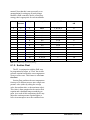
7.3. VIEWING THE PAK STATUS SCREEN .......................................................................................................................... 26
7.3.1. Inputs and Set Points........................................................................................................................................... 26
7.3.2. Compressor Groups ............................................................................................................................................ 27
7.3.3. Compressor Status............................................................................................................................................... 27
7.3.4. Condenser Fans................................................................................................................................................... 27
7.3.5. Connected and PAK State ................................................................................................................................... 28
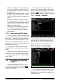
7.4. PROGRAMMING THE PAK USING E2........................................................................................................................... 28
7.4.1. Screen 1: General................................................................................................................................................ 28
7.4.2. Screen 2: Comp Setpts......................................................................................................................................... 28
7.4.3. Screen 3: Cond Setpts ......................................................................................................................................... 29
7.4.4. Screen 4: Float Setup .......................................................................................................................................... 29
7.4.5. Screen 5: PAK Inputs .......................................................................................................................................... 29
7.4.6. Screen 6: Outputs ................................................................................................................................................ 30
7.4.7. Screen 7: PAK Outputs ....................................................................................................................................... 30
7.4.8. Screen 8: Fixed Steps .......................................................................................................................................... 30
7.4.9. Screen 9: Safety................................................................................................................................................... 31
7.4.10. Screen B: Alarms............................................................................................................................................... 31
8 MULTIFLEX PAK HAND-HELD TERMINAL INTERFACE ............................................................................. 32
8.1. THE HHT INTERFACE ................................................................................................................................................. 32
vi • MultiFlex I/O Board I&O Manual
026-1722 Rev 4 03-JUN-2010
8.1.1. Navigation...........................................................................................................................................................
8.2. PAK START SCREENS .................................................................................................................................................
8.3. PAK STATUS SCREENS ...............................................................................................................................................
8.3.1. Status Screen 1 ....................................................................................................................................................
8.3.2. Status Screen 2 ....................................................................................................................................................
8.3.3. Status Screen 3 ....................................................................................................................................................
8.3.4. Status Screen 4 ....................................................................................................................................................
8.3.5. Status Screen 5 ....................................................................................................................................................
8.3.6. Status Screen 6 ....................................................................................................................................................
8.3.7. Status Screen 7 ....................................................................................................................................................
8.3.8. Status Screen 8 ....................................................................................................................................................
8.3.9. Status Screen 9 ....................................................................................................................................................
8.3.10. Status Screen 10 ................................................................................................................................................
8.3.11. Status Screen 11 ................................................................................................................................................
8.4. PAK CONFIGURATION SCREENS ................................................................................................................................
8.4.1. The PAK Configuration Menu ............................................................................................................................
8.4.1.1.
8.4.1.2.
8.4.1.3.
8.4.1.4.
8.4.1.5.
8.4.1.6.
1 - General ........................................................................................................................................................................
2 - Comp SP ......................................................................................................................................................................
3 - Outs..............................................................................................................................................................................
4 - CondSP ........................................................................................................................................................................
5 - Input.............................................................................................................................................................................
6 - Safety ...........................................................................................................................................................................
32
33
33
33
33
33
34
34
34
35
35
35
35
35
36
37
37
38
40
41
43
44
Table of Contents • vii
1
Overview of the MultiFlex Product Line
The MultiFlex line of control system boards
provides a wide variety of input, output, and
smart control solutions, all of which are based on
a single universal hardware platform. The board
design uses flash-uploadable firmware and plugin expansion boards to configure the base platform board and apply it for use as an input
board, relay output board, analog output board,
or a combination I/O board.
1.1.
MultiFlex PAK
The PAK is a distributed pack controller that
controls compressors and condenser fans. The
PAK can control up to 16 compressors, controlled in up to 8 compressor groups.
The PAK can control up to 4 condenser fan
groups containing up to 8 total condenser fans.
The PAK condenser control strategy is sequential TD control with setpoint/deadband using ON
and OFF delays. The PAK supports use of both
single-speed fan stages and VS fans.
1.1.1. Hardware
The MultiFlex PAK boards consist of two
circuit boards: a bottom layer with 16 combination digital/analog inputs, and a plug-in top layer
which contains a combination of 8 relay outputs
and 4 analog DC voltage outputs, which can be
used as digital or analog outputs.
The communication interface is RS485 I/O
using the Standard Extended Address Form for
CPC Distributed Controllers. Currently, the PAK
is designed to interface with the CPC E2 RX
controller, and the previous generation refrigeration controller, the Einstein RX.
MultiFlex PAK
Overview of the MultiFlex Product Line • 1
2
Mounting and Powering
The MultiFlex boards are usually installed
by the refrigeration or building equipment manufacturer. Therefore, the installer need only
make the necessary connections between the
boards and the site controller(s).
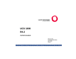
2.1.
Snap-Track Installation
MultiFlex boards not supplied in a custom
panel or other enclosure are supplied with a
snap-track for easy installation. The insulation
sheet and I/O board must be removed from the
track before the track is mounted. The snap-track
is mounted using the 0.1875” mounting slots.
Figure 2-1 shows this installation procedure.
In some instances, an installer may be
required to mount an I/O board. There are no
restrictions on the location of these boards; however, for ease of network configuration, it is recommended that the boards be located adjacent to
the E2. I/O boards may be mounted without an
enclosure, but they should be mounted in a location that is not easily accessible to avoid tampering or damage.
Figure 2-1 - MultiFlex Snap-Track Mounting
Figure 2-2 provides mounting dimensions
for the MultiFlex board.
Figure 2-2 - MultiFlex Board Dimensions
2 • MultiFlex I/O Board Operator’s Guide
026-1722 Rev 4 03-JUN-2010
2.2.
The additional board makes the MultiFlex
combination boards considerably taller than the
MultiFlex 16 and all previous-generation CPC I/
O boards. If you will be mounting these boards
in an enclosure, the board will need at least 2.5"
of clearance between the base board and the
panel door.
The Plug-In Output
Board
2.3.
Powering the MultiFlex
All models of MultiFlex require a 24VAC
Class 2 input power source. The MultiFlex PAK
requires the power source to be center-tapped.
CPC supplies a wide variety of 24VAC transformers with varying sizes and either with or
without center taps. Table 2-1 shows the transformer sizes and whether they are center-tapped
or non-center-tapped.
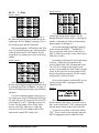
Figure 2-3 - Exploded View -- MultiFlex Combination I/O Board
All MultiFlex boards except the MultiFlex
16 have output sub-boards that plug in to the top
of the base board. These boards are shipped with
the output board pre-installed on the board using
stand-offs, so no additional hardware setup
should be necessary.
Xformer P/N
VA Rating
Primary Voltage
Center Tap?
640-0041
50 VA
110 VAC
No
640-0042
50 VA
220 VAC
No
640-0056
56 VA
Multi-tap (120/208/240 VAC)
Yes
640-0050
75 VA
110 VAC
No
640-0045
75 VA
220 VAC
No
640-0080
80 VA
Multi-tap (120/208/240 VAC)
Yes
Table 2-1 - Transformers Compatible with MultiFlex Board
The Plug-In Output Board
Mounting and Powering • 3
2.3.1. Choosing Transformer Sizes
In most site installations, a single transformer will power multiple devices. Choose a
transformer with a VA rating large enough to
power all devices that will be attached to it.
Table 2-2 gives the VA ratings of the MultiFlex
board products. Refer to your site controller’s
manual for VA ratings of the other I/O boards
that may be powered by one of these transformers.
Unit
VA
VAC
Center
tapped?
MultiFlex PAK,
15
24
NO
MultiFlex 16
6
24
Yes
MultiFlex 88,
88AO, 168,
168AO and
168DO
15
24
NO
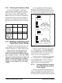
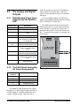
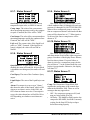
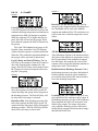
A new-style MultiFlex PAK board has a
green power LED located next to the 24VAC
connection terminal in the upper right corner of
the circuit board (see Figure 2-4 for reference).
24 VAC
POWER LED
New Style
MultiFlex Board
(Top Left Corner)
CUB, RTU,
and RCB
24 VAC
NO POWER LED
Old Style
MultiFlex Board
(Top Left Corner)
Table 2-2 - Device Power Requirements
2.3.2. MultiFlex Combination Input/
Output Board Power Wiring
The MultiFlex PAK boards do not use a center tap. Instead, the 0V terminal on the board
should be connected to a separate Earth ground.
Important! The rules that must be followed when connecting a MultiFlex PAK
board to a transformer are different depending on whether you have a "new style" MultiFlex board with an isolated power supply (all
MultiFlex boards shipped after November 1,
2002) or an "old style" MultiFlex board (all
MultiFlex boards shipped before November
1, 2002).
Figure 2-4 - New-Style vs. Old-Style MultiFlex Board
If there is a power LED next to the connector, your MultiFlex is a new-style MultiFlex -refer to Section 2.3.2.1., New-Style MultiFlex
Combination I/O Boards (with Isolated Power
Supply) for power wiring instructions.
If there is no power LED next to the connector, your MultiFlex is an old-style MultiFlex -refer to Section 2.3.2.2., Old-Style MultiFlex
Combination I/O Boards (No Isolated Power
Supply) for power wiring instructions.
2.3.2.1.
New-Style MultiFlex Combination I/O Boards (with Isolated
Power Supply)
The new-style MultiFlex board can be connected to any of the center-tapped transformers
mentioned in Table 2-2, provided the 0V terminal of the board is connected to an Earth ground.
4 • MultiFlex I/O Board Operator’s Guide
026-1722 Rev 4 03-JUN-2010
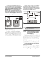
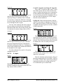
A center-tapped transformer may power
both center-tapped and non-center-tapped boards
at the same time, as long as none of the noncenter-tapped MultiFlex boards are old-style
MultiFlex boards. If an old-style MultiFlex
shares the same center-tapped transformer as a
device that uses the center tap, boards on the network will be damaged. Figure 2-5 shows how to
wire a non-center tapped device to a centertapped transformer.
You may also tie one side of the secondary
(but not BOTH sides) or the center tap to an
earth ground, provided none of the boards powered by the same transformer are old-style MultiFlex boards (see Section 2.3.2.2.).
Figure 2-6 - Non-Center-Tapped Transformer Wiring
All wire connections to earth ground should
be less than six (6) inches long and use a wire
gauge of at least 14AWG.
Figure 2-5 - Wiring Non-Center Tapped MultiFlex Boards to
Transformers With a Center Tap
In addition, the MultiFlex combination
boards can be powered by one of the 50VA or
75VA non-center-tapped transformers listed in
Table 2-1 on page 3. Figure 2-6 shows how to
wire the transformers to the MultiFlex boards.
2.3.2.2.
Old-Style MultiFlex Combination I/O Boards (No Isolated
Power Supply)
Like the new-style MultiFlex board, the oldstyle MultiFlex board can be connected to any of
the center-tapped transformers mentioned in
Table 2-2, provided you follow the following
three rules:
Rule 1: Ground the 0V terminal on the oldstyle MultiFlex board to an Earth ground.
Do not connect the center tap of the transformer to the 0V terminal.
Rule 2: Do not power an old-style MultiFlex
non-center-tapped board with a transformer
that is also powering a center-tapped device.
Powering the MultiFlex
Mounting and Powering • 5
This means you cannot connect an old-style
MultiFlex non-center tapped board to a transformer that is powering a MultiFlex 16, 16AI,
8RO, 4AO, 8DO, a Gateway board, or any previous generation CPC board that uses centertapped power. Doing so will destroy the MultiFlex board.
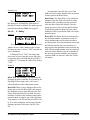
the transformer that supplies power to them is
not enough to be concerned with. But it is very
important not exceed this maximum wire length
or the boards will malfunction.
Use these formulas to determine if the wire
gauge you are using fits within specification:
Rule 3: The secondary of the transformer
must not be grounded on any side.
14 AWG:
Verify that neither side of the transformer
secondary is connected to earth ground before
powering the old-style MultiFlex board. A
grounded secondary will damage the MultiFlex
board.
18 AWG:
In addition, the old-style MultiFlex combination boards can be powered by one of the 50VA
or 75VA non-center-tapped transformers listed
in Table 2-1 on page 3. Figure 2-6 shows how to
wire the transformers to the MultiFlex boards.
18 AWG: 9 ft.
Feet = 0.40/(VA/24) x 0.005
Feet = 0.40/(VA/24) x 0.013
(VA is the total VA rating of the I/O boards)
For example, if you had an 80 VA load:
14 AWG: 24 ft. (rounded down)
Figure 2-7 - Power Wire Lengths
2.3.3. Wire Types and Maximum
Distances
For powering I/O boards, use only the listed
wire types from Table 2-3. Three-conductor nonshielded cables are the recommended wire for
connecting between the center tapped transformer and the I/O boards. Shielded cable should
not be used for power wiring. The center tap
should be wired with the third conductor to earth
ground at the transformer.
Each MultiFlex board should have its 0V terminal taken to a short, solid earth ground.
Power Wiring Types
14 AWG
Belden 9495 or equivalent
18 AWG
Belden 9493 or equivalent
Table 2-3 - Power Wiring Types
The wire length from the transformer and the
number of boards connected to the same wire
determines the type wire gauge used. In most
cases, the distance between the I/O boards and
6 • MultiFlex I/O Board Operator’s Guide
026-1722 Rev 4 03-JUN-2010
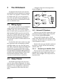
3
The I/O Network
A diagram of this network arrangement is
shown in Figure 3-1.
All MultiFlex PAK boards and controllers
use an RS485 network connection to communicate with E2 site controllers. Technicians who
are familiar with CPC’s previous generation
16AI, 8IO, and ARTC boards will find the network setup procedure for the MultiFlex boards
to be very much the same.
3.1.
TERMINATION
Wiring Types
CPC specifies all RS485 I/O and MODBUS
wiring used by the E2 must be Belden 8641
(24AWG, 300V, CPC P/N 135-8641); Belden
8761 (22 AWG, 300V not stocked by CPC); or a
600V-shielded 22AWG equivalent stocked by
CPC (P/N 135-0600). These are two-connector
shielded twisted pair cable that support a maximum daisy chain cable distance of 4000 feet
(1219 m) between the E2 and the end device on
the network.
Provided the cable can be routed away from
noise generators and avoid running in parallel
with high-voltage wire, any of the three specified cables will provide adequate shielding from
external noise. For more instructions on best
practices for minimizing noise, refer to publication 026-1903, E2 Controller Wiring Practices,
available in the Product Manuals section of the
Emerson Retail Solutions website (http://
www.emersonretailsolutions.com/library).
3.2.
TERMINATION
Figure 3-1 - I/O Network Configurations
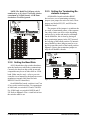
3.2.1. Network ID Numbers
Each device on an RS485 segment has a network dip switch that must be used to assign the
board a unique network ID number.
The network ID number makes a board
unique from other boards on the network of the
same type. This allows the site controller to find
it and communicate with it.
Boards of the same type should be numbered
in sequence, starting with one and continuing
with two, three, etc.
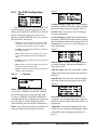
3.2.1.1.
Numbering the MultiFlex PAK
The network ID on the MultiFlex PAK is set
using the first five dip switches on dip switch
bank S3. Refer to Figure 3-2 for dip switch setting instructions.
Daisy Chains
The RS485 Input/Output (I/O) network is
wired in a daisy-chain configuration. In a daisy
chain, boards are wired together in series with no
branches or "star configurations," and the network is terminated at either end of the daisy
chain.
Wiring Types
The I/O Network • 7
NOTE: The MultiFlex PAK may only be
numbered up to 16, since E2 will only speak to
a maximum of 16 PAK boards. A PAK numbered above 16 will be ignored.
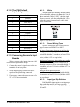
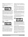
3.2.3. Setting the Terminating Resistance Jumpers
All MultiFlex boards and other RS485
devices have a set of terminating resistance
jumpers (one jumper for each wire lead). These
jumpers are labeled JP2, JP3, and JP4 on the
MultiFlex board.
The purpose of the jumpers is to indicate the
two ends, or termination points, of the segment.
On a daisy chain, one device at the beginning
and one device on the end must be terminated.
On the MultiFlex, this is done by placing all
three termination jumpers in the OUT (toward
the left edge of the board) position. To unterminate a MultiFlex, these jumpers must be set to
the IN (toward the center of the board) position.
Figure 3-3 shows the termination jumper settings for all MultiFlex boards.
Figure 3-2 - 16 Network ID and Baud Rate Switches
3.2.2. Setting the Baud Rate
All I/O boards have dip switches that determine the baud rate at which they communicate.
Currently, the baud rate dip switch in network
components may be set at either 9600 or 19200
baud. Either may be used -- refer to your site
controller’s user manual for the baud rate recommendation (currently 9600 baud for both
REFLECS and E2 controllers).
Figure 3-3 - I/O Network Termination Jumper Settings
On all MultiFlex boards, switches 6 and 7 on
S3 are used to set the baud rate. To communicate
at 9600 baud, set switch #6 UP and #7 DOWN.
For 19200 baud, set switch #6 DOWN and #7
UP. Refer to Figure 3-2 for a visual look at how
the switches must be set.
8 • MultiFlex I/O Board Operator’s Guide
026-1722 Rev 4 03-JUN-2010
4
4.1.
I/O Board Input and
Output Setup
The Inputs
The inputs on a MultiFlex board are compatible with a wide range of analog and digital sensors and transducers. In general, the inputs are
capable of reading analog voltage signals in the
range of 0V to +7VDC and dry-contact (no outside voltage) digital sensors and switches.
The specific types of input devices that must
be used with MultiFlex is largely dependent on
the site controller MultiFlex is connected to;
refer to the site controller’s user’s manual for a
full list of compatible sensors and specific sensor wiring instructions.
4.1.1. Input Types Supported by
the MultiFlex PAK
Input Type
Description
Suct Xdcr
Pressure transducer measuring
suction pressure
Disch Xdcr
Pressure transducer measuring
discharge pressure
Amb Temp 1
Temperature sensor measuring
outdoor air temperature
Amb Temp 2
Optional second ambient air
temperature sensor. Will be
combined with Amb Temp 1 to
determine the ambient air temp
DischTemp 1-8
Compressor discharge temperature sensors for compressors
#1 through #8
Liq Level
Liquid level transducer
Comp Amps
Current transducer measuring
current on the compressor pack
Cond Amps
Current transducer measuring
current on the condenser
Suct Temp
Suction return air gas temperature
Dig Fault
External digital fault detection
device - CLOSED when the
pack is failed
Alarm Reset
Input used for switch or pushbutton to reset alarms active on
the PAK
VSD Fault
Connected to the fault output
from the VS Fan inverter - notifies the PAK of an inverter failure
Liq Level
Dry-contact liquid level sensor
Table 4-1 - MultiFlex PAK Input Types
The Inputs
I/O Board Input and Output Setup • 9
4.1.2. The PAK Default
Input Assignments
Analog Input #
Definition
1
Suct Xdcr
2
Disch Xdcr
3
Amb Temp 1
4
Amb Temp 2
5
Suct Temp
6
Comp Amps
7
Cond Amps
8
Liq Level
9
DischTemp 1
10
DischTemp 2
11
DischTemp 3
12
DischTemp 4
13
DischTemp 5
14
DischTemp 6
15
DischTemp 7
16
DischTemp 8
Table 4-2 - MultiFlex PAK Default Inputs
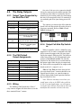
4.1.3. Connecting Sensors to Input
Boards
Wiring a sensor to the input points on a MultiFlex board requires three steps:
1. Connect the sensor’s signal wires to the two
terminals of an input point.
2. Set the input type dip switch that corresponds to the point being connected.
3. If necessary, connect the sensor to one of the
5V or 12V power terminals.
4.1.3.1.
Wiring
An input point on a MultiFlex board consists
of two terminals, as shown in Figure 4-1. One of
these terminals, labeled “SIG,” reads the signal
from the sensor, while the other, labeled “0v” is
where the sensor’s ground and/or cable shield
wire is connected.
Figure 4-1 - Input Board Points
4.1.3.2.
Sensor Wiring Types
Specific wiring types are required for each
type of sensor used with E2 or RMCC.
All Analog Temperature Sensors and Air Flow Sensors
Temperature and air flow sensors are to be
wired with shielded, 2 conductor, at least 22 GA
wire (Belden # 8761 or equivalent).
All Pressure Transducers, Humidity Sensors, and Refrigeration Transducers
Pressure and refrigeration transducers and
humidity sensors are to be wired with shielded, 3
conductor, at least 22 GA wire (Belden #8771 or
equivalent).
Dew Point and Light Level Sensors
These sensors are to be wired with shielded,
4 conductor at least 22 GA wire (Belden # 8729
or equivalent).
4.1.3.3.
Input Type Dip Switches
Each MultiFlex input point has an input type
dip switch that must be set. Input type dip
switches are located in the switch banks labeled
S1 and S2.
10 • MultiFlex I/O Board Operator’s Guide
026-1722 Rev 4 03-JUN-2010
The input type dip switch tells the input
board whether or not the sensor connected to the
point is a resistive type sensor. Generally, if the
sensor or transducer supplies its own voltage
signal to the point, the dip switch should be set
to the LEFT (OFF) position. If the sensor uses
variable resistance and requires voltage to be
supplied to it from the input point, set the dip
switch to the RIGHT (ON) position. Dip
switches for unused points should be set to the
RIGHT (ON) position.
The exception to this rule is for CPC’s
5VDC pressure transducers -- though they
supply their own voltage signal, the dip switch
MUST be set to the RIGHT (ON) position.
4.1.4. Power Connection
If power is needed to operate the sensor, four
points are provided on the MultiFlex board that
supply DC power: one +12VDC point, and three
+5VDC points. See Figure 4-2 for the location
of these points.
4.1.4.2.
Powering Sensors Requiring
24VAC Off the Power Transformer
Some sensors that requires 24VAC can be
powered off the MultiFlex’s own 24VAC power
connection. To connect to the 24VAC power
source, connect the sensor’s power wires to terminals AC1 and AC2.
This can only be done with sensors that keep
the 24VAC signal isolated from its DC output
signal (such as CPC’s Dew Point Probe). If the
output signal is not isolated from the 24VAC
input, you must use a separate transformer.
4.1.5. Sensor Types for MultiFlex
Input Points
Because different controllers may be compatible with different sensor types, this manual
cannot list all sensor types and how to wire them
to a MultiFlex input point. Refer to your site
controller’s documentation for sensor wiring
information.
Figure 4-2 - Input Board Power Sources
4.1.4.1.
Current Ratings for On-Board
Power Sources
The maximum current that may be drawn
from the +12VDC terminal is 100 milliamps.
The maximum current that can be drawn from
all three +5VDC terminals COMBINED is 50
milliamps.
The Inputs
I/O Board Input and Output Setup • 11
4.2.
The Relay Outputs
4.2.1. Output Types Supported by
the MultiFlex PAK
Output Type
Description
Comp Grp1-8
Compressor Group output 1-8
Fan Stage 1-4
Fan Stage output 1-4
Liq Inject
Condenser Liquid Injection
valve
Cond Spray
Condenser Spray valve
Alarm
Compressor discharge temperature sensors for compressors
#1 through #8
VSD Fan Enable
"Run" input for an inverter operating the variable-speed fan(s)
VSD Bypass
Bypass input for an inverter operating the variable-speed
fan(s)
VSD Reset
Reset input for an inverter operating the variable-speed fan(s)
Table 4-3 - MultiFlex PAK Output Types
4.2.2. The PAK Default
Output Assignments
Relay Output #
Definition
1
Comp Grp 1
2
Comp Grp 2
3
Comp Grp 3
4
Comp Grp 4
5
Comp Grp 5
6
Comp Grp 6
7
Comp Grp 7
8
Comp Grp 8
Table 4-4 - MultiFlex PAK Default Outputs
4.2.3. Wiring
The MultiFlex PAK boards have Form C
relay contacts. Figure 4-3 shows how to wire the
three-terminal Form C contact.
12 • MultiFlex I/O Board Operator’s Guide
One wire of the two-wire connection should
always be connected to the middle terminal. The
second wire must either be connected to the N.C.
terminal (if you want the path to be closed when
the relay is de-energized) or the N.O. terminal (if
you want the path to be open during power failure).
The contacts you choose also affect what the
board’s fail-safe dip switch will need to be set to
for proper operation. Refer to Table 4-5 and
Table 4-6 on page 13.
RELAY IS
CLOSED
ON POWER
FAILURE
N.C.
N.O.
RELAY IS
OPEN ON
POWER
FAILURE
N.C.
N.O.
Figure 4-3 - Form C Contact Wiring
4.2.4. Output Fail-Safe Dip Switches
When a controller calls for a MultiFlex relay
output to be ON, it sends a command to the MultiFlex to turn the output to the ON state (signified by the output LED being ON). The behavior
of the relay when it is ON is determined by the
position of the fail-safe switch. The fail-safe
switches for the outputs are on a switch bank at
the bottom right corner the plug-in output module. Each switch corresponds to an output on the
board (switch #1 = output #1, etc.).
Table 4-5 and Table 4-6 show how the failsafe switch and Form C contacts should be configured based on how you want the output to
perform during both normal operation and during network/power loss.
Note: There are not many cases where you
would want a relay to be OPEN when called to
be ON. For most applications, you will want to
set the fail-safe switch to UP so that an ON command from the controller will close the relay.
026-1722 Rev 4 03-JUN-2010
State of Normally Closed (N.C.) Contacts
on MultiFlex Relay Points
Fail-safe
Switch
Light
is ON
Light
is OFF
Loss of
Communi
cation
Loss of
Power
Up (ON)
Closed
Open
Closed
Closed
Down (OFF)
Open
Closed
Closed
Closed
Table 4-5 - Output Board Fail-Safe and Switch Settings when Contact is Wired Normally Closed (N.C.)
State of Normally Open (N.O.) Contacts on
MultiFlex Relay Points
Fail-safe
Switch
Light
is ON
Light
is OFF
Loss of
Communi
cation
Loss of
Power
Up (ON)
Open
Closed
Open
Open
Down (OFF)
Closed
Open
Open
Open
Table 4-6 - Output Board Fail-Safe and Switch Settings when Contact is Wired Normally Closed (N.O.)
4.2.5. Relay Output Ratings and
Fuse Protection
Each relay output on the MultiFlex Combination I/O boards is rated for up to 240 VAC
with a maximum current of 2 amps.
Each relay is fused with a 2A fast-blow 5mm
x 20mm fuse, Bussman GMA-2 or equivalent.
The Relay Outputs
I/O Board Input and Output Setup • 13
The Analog and Digital
Outputs
4.3.1. Digital/Analog Output Types
Supported by the MultiFlex
PAK
Output Type
Description
Comp Grp1-8
Compressor Group output 1-8
Fan Stage 1-4
Fan Stage output 1-4
Liq Inject
Condenser Liquid Injection
valve
Cond Spray
Condenser Spray valve
Alarm
Compressor discharge temperature sensors for compressors
#1 through #8
VSD Fan Enable
"Run" input for an inverter operating the variable-speed fan(s)
VSD Bypass
Bypass input for an inverter operating the variable-speed
fan(s)
VSD Reset
Reset input for an inverter operating the variable-speed fan(s)
VSD Analog
Fan speed input for an inverter
operating the variable-speed
fan(s)
Fan Seq
Variable-voltage output driving
a fan sequencer
For use as digital outputs, the MultiFlex
PAK may be configured in the software to define
0/8V as ON/OFF or as OFF/ON.
The PAK has no hardware-based fail-safe
settings (fail-safes are set up in the board firmware). All that is required is to connect the “+”
terminal to the positive wire on the device and
the “-” terminal to the negative (or ground) wire
of the device.
DIGITAL
4.3.
VSD. Each output is rated up to 10 milliamps.
These outputs are fixed to drive solid-state
relays for activation/deactiviation of condenser
fan stages.
Table 4-7 - MultiFlex PAK Output Types
4.3.2. The PAK Default Analog/Digital Output Assignments
Analog/Digital
Output #
Definition
1
Fan Stage 1
2
Fan Stage 2
3
Liquid Inject
4
Condenser Spray
Figure 4-4 - MultiFlex Digital Points
Table 4-8 - MultiFlex PAK Default Outputs
The MultiFlex PAK board has four outputs
that may act as either digital outputs that pulse a
+8VDC signal, or as analog outputs that use a
variable voltage to drive a fan sequencer or
14 • MultiFlex I/O Board Operator’s Guide
026-1722 Rev 4 03-JUN-2010
5
Board Status LEDs
When a MultiFlex board is powered up, you
will be able to determine the operating status of
the board by observing its status LEDs. Figure
5-1 shows the location of the MultiFlex’s status
LEDs.
Figure 5-1 - MultiFlex Status LED Locations
5.1.
Status LED
The Status LED simply blinks GREEN once
per second to show that the board is powered
and operational. If this light is dark, the board
has likely lost power.
5.2.
Tx and Rx LEDs
The Tx and Rx LEDs indicate when the MultiFlex is sending or receiving messages on the
RS485 network.
The Tx LED blinks once every time the MultiFlex sends a response to the E2 or REFLECS.
The Rx LED blinks once when the MultiFlex
receives a message.
If the MultiFlex is connected to the network
and set up to communicate with the controller,
you should see these lights blinking regularly. If
they do not, there may be a problem with the network.
5.3.
Code A and Code B LEDs
The MultiFlex PAK has two LEDs labeled
Code A and Code B. These LEDs indicate failure conditions. When these LEDs are OFF, there
are no failures active. When one or both of these
LEDs are blinking, there are failure conditions.
The rate of blinking indicates the type of failure:
Code A Failure Conditions
• Blinking fast (4 times/second) - There is a problem
with the flash memory or hardware clock on this
board. This generally means the board is bad and
must be replaced.
• Blinking slow (1 time/second) - The board is not receiving any messages addressed to it. This means either the I/O network is down or it has not yet been
Status LED
Board Status LEDs • 15
commissioned in the E2 or REFLECS Network
Configuration screen.
Code B Failure Conditions
• Blinking 2 times/second - This indicates the board
has lost its configuration. If Code B blinks at this
rate on an operational board, it means the board
must be reprogrammed.
This light does not blink if the board is new or is using the unmodified default configuration.
5.4.
Relay Output LEDs
Each relay output point on a MultiFlex has
an indicator LED that shows the status of the
output. This LED is lit to show the output is ON,
and unlit to show the output is OFF.
The definition of ON and OFF in this case is
determined by the position of the fail-safe dip
switch (see Table 4-5 and Table 4-6).
16 • MultiFlex I/O Board Operator’s Guide
026-1722 Rev 4 03-JUN-2010
6
6.1.
PAK Software Overview
Compressor Groups
6.1.1. Maximum # of Groups
The maximum number of compressor groups
is eight. Each compressor group corresponds to a
physical relay point on a MultiFlex board. PAK
activates and deactivates compressor groups in
order to control the suction pressure.
The total maximum number of individual
compressors that can be controlled by the PAK is
sixteen, regardless of how many compressor
groups these compressors are associated with.
Compressors are only activated or deactivated as
part of a compressor group; however, a PAK
input may be set up to read the discharge temperature for any or all of the compressor groups.
The number of compressors that may belong
to a single compressor group is limited by the
amperage rating on the MultiFlex output point
(max. 2A up to 240VAC).
Note: When splitting up compressors into
the eight groups, the total compressor HP should
be spread out as much as possible to make use of
as many compressor groups as possible.
6.1.2. Required Setpoints
The setpoints required for compressor group
operation are: Suction Setpoint, Suction Deadband, Suction Outer Deadband, and fixed-step
ON and OFF delay times. You will also need to
configure which groups will be ON for each step
in the fixed step strategy.
6.1.3. Compressor Group Stage
Activation and Deactivation
For both Cyclic and Fixed Step compressor
group control strategies, the setpoints required
are:
Compressor Groups
Suction Setpoint. The suction pressure you
wish to maintain.
Suction Deadband. A small range of values
equally above and below the Suction Setpoint,
within which the suction pressure will be considered to be acceptably near the Suction Setpoint
and no stage activation or deactivation will
occur.
Step ON and OFF delay times. The Step ON
delay time is observed immediately after the
PAK adds compressor capacity (either by
cycling ON a larger number of compressors or
by incrementing up one step in the Fixed Step
strategy). If after bringing ON more compressors
the suction pressure is still above the top part of
the Suction Deadband, it must wait an amount of
time equal to the Step ON delay before considering a
Suction Outer Deadband. A larger range of
values equally above and below the Suction Setpoint (larger than the Suction Deadband). The
Suction Outer Deadband seeks to prevent an
unnecessary activation or deactivation of compressor group stages in instances where the suction pressure is just barely outside of the Suction
Deadband and already moving back toward the
setpoint.
When the suction pressure lies somewhere
between the inner and outer deadband, it analyzes the direction and rate of change of the suction pressure over the last 1/2 of the Step ON or
Step OFF delay (depending on the direction). If
the calculated slope of the suction pressure during the last 1/2 of the delay indicates the suction
pressure will return to within the Suction Deadband range in an amount of time equal to an
additional Step ON or Step OFF delay, it will
delay compressor stage changing for one delay
period.
Example: a PAK has a suction setpoint of
45PSI, a Suction Deadband of 4PSI, a Suction
Outer Deadband of 8PSI, and a Step ON and
Step OFF delay of 30 seconds each. With all
PAK Software Overview • 17
stages turned OFF, the suction pressure climbs
from 45PSI to 49PSI, taking it above the top
edge of the Suction Deadband. With the Step ON
delay already satisfied, the PAK will cycle ON a
compressor group.
After cycling the group ON, since 49PSI is
between the inner and outer deadband, the PAK
will analyze the direction and slope of the suction pressure change. Fifteen seconds after the
first stage activation (1/2 the Step ON delay), the
suction pressure is measured to be 48.5PSI. At
the end of the Step ON delay, the pressure is
48.0PSI.
Since the pressure is currently changing at a
rate of -1PSI per Step ON delay period, the PAK
will determine that, even though the pressure is
still above the top edge of the Suction Deadband,
if another Step ON delay period were to elapse
with no further activations, the pressure at the
end of the next delay period would be 47PSI
(within the deadband). In this case, the PAK will
not activate more compressors and will remain
in the current state for at least one more Step ON
delay period.
In the next Step ON delay period, the pressure measured at the first 15 seconds is 47.2PSI,
and the pressure measured at the end of the Step
ON delay period is 47.3PSI. In this case, the
pressure is both above the top edge of the Suction Deadband and increasing rather than moving toward the setpoint. In this case, the PAK
will activate the next stage, bringing on more
compressors.
6.1.4. Compressor Control Strategies
6.1.4.1.
Cyclic
"Cyclic" activates and deactivates compressor groups using a First-ON, First-OFF strategy.
18 • MultiFlex I/O Board Operator’s Guide
When the PAK must add one compressor
group, the group it selects will be the one that
has been OFF for the longest amount of time.
Likewise, when the PAK must deactivate a compressor group, it will deactivate the group that
has been ON for the longest amount of time.
The advantage to the Cyclic strategy is over
time the runtime of all compressor groups will
be evenly distributed (also ensuring no compressors go inactive for long periods of time, thus
preventing compressor failure due to lack of
use). The drawback is, Cyclic strategy assumes
all compressor groups are the same size in terms
of HP or amp ratings. If the compressor groups
are differing sizes, performance is likely to suffer when using the Cyclic strategy.
6.1.4.2.
Fixed Steps
The Fixed Step strategy sequences through a
series of programmed compressor group ON/
OFF combinations as the PAK requires more or
less horsepower to maintain set point.
When the PAK requires activation of more
compressor capacity, the PAK activates the next
highest numbered combination, or "step." When
the PAK requires deactivation of compressors,
the PAK goes to the next lowest numbered step.
The Step ON and Step OFF delay is observed
between each transition to prevent rapid cycling.
The maximum number of steps that may be
configured is 20.
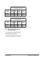
Example of Fixed steps
Table 6-1 shows an example of a fixed step
strategy for a pack of 13 equally sized compressors. The compressors are split into five groups
(one for each relay on the MultiFlex PAK).
Then, for each of the 14 total steps in the strategy, each step is configured to bring on a different combination of groups, resulting in the total
number of compressors increasing or decreasing
by 1 every time a step is incremented or decre-
026-1722 Rev 4 03-JUN-2010
mented. Note that this is not necessarily a recommendation for setting up all packs using a
MultiFlex PAK controller; choose a fixed step
strategy that is appropriate for each installation.
Group
# Compressors
Step
Group ON
Group OFF
# of Compressors
ON
1
1
1
None
1, 2, 3, 4, 5
0
2
3
2
1
2, 3, 4, 5
1
3
3
3
5
1, 2, 3, 4
2
4
4
4
1, 5
2, 3, 4,
3
5
2
5
1, 2
3, 4, 5
4
6
2, 5
1, 3, 4
5
7
2, 3
1, 4, 5
6
8
3, 4
1, 2, 5
7
9
1, 3, 4
2, 5
8
10
3, 4, 5
1, 2
9
11
1, 3, 4, 5
2
10
12
1, 2, 3, 4
5
11
13
2, 3, 4, 5
1
12
14
1, 2, 3, 4, 5
None
13
Table 6-1 - Example Setup of Fixed Step Strategy
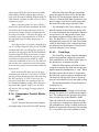
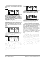
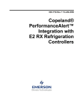
6.1.5. Suction Float
The E2, in conjunction with the PAK, may
be programmed to adjust, or "float" the suction
pressure setpoint based on the case temperatures
of one or more cases. This feature is called suction float.
Suction float combines the case temperatures
from up to 20 different sources into a single temperature value (either by taking the average
value, the median value, or the maximum value).
This value is then compared to the suction float
setpoint and a deadband range around the setpoint. As a result of this comparison, the E2 may
adjust the suction pressure setpoint higher or
lower in an attempt to move the combined case
Compressor Groups
PAK Software Overview • 19
temperature in line with the float setpoint. A
graph showing an example of suction pressure
setpoint adjustment versus float temperature is
provided in Figure 6-1.
Each case temperature input value used in
the combination is determined by taking the
average value of the input over a time window
(called the averaging window), which averages
all sampled temperatures between the current
time and x minutes before the current time
(where x is the user-defined averaging window
time period). Once the averages of each input are
determined, these values are then combined into
a single temperature by calculating either the
average value, the median value, or the maximum value. The result, called the float temperature, is compared to the float setpoint to
determine which direction to float the suction
pressure setpoint.
6.1.5.2.
Defrost Inhibit
All case temperatures used as inputs for Suction Float are only used in the combined case
temp calculation if they are in refrigeration
mode. If a case is not in refrigeration mode, its
temperature input value will be ignored.
Figure 6-1 - Suction Pressure Setpoint Vs. Float Temperature
The amount of the interval for each adjustment, as well as the frequency of adjustment, is
programmable by the user. Also, the user must
specify a minimum and maximum range for the
suction setpoint to prevent suction float from
floating the setpoint too high or too low.
6.1.5.1.
Suction Float Input Sources
Up to 20 case temperatures may be used to
provide the combined case temperature used
during suction float. The E2 may use case temperatures from:
•
•
•
•
•
Standard Circuit applications in the E2,
Emerson Climate Technologies EC2 case
controllers,
Danfoss EKC514 SNMP case controllers,
WCC case controller (Microm/Tektronix/
Barker/Elm/CDK),
Danfoss DFMC Micro-Cool case controllers.
20 • MultiFlex I/O Board Operator’s Guide
This includes cases in defrost, pump down,
drip or "drain" mode, clean or "wash" mode, and
cases whose case control devices are offline or
otherwise shut down.
If a case that is being inhibited returns to
refrigeration mode, the E2 will wait for a userdefined delay period to elapse before including
its temperature value in the combined case temp
calculation. The inhibit delay is designed to
allow the case enough time to recover its case
temperature setpoint.
6.1.5.3.
Bad Case Temp Inhibit
In addition to excluding case temperatures
from circuits or case controllers that are not in
refrigeration, the PAK application in the E2 will
exclude up to a user-defined number of case
temperatures from cases determined to be "poor
performers." A poor-performing case is defined
as one whose temperature deviates outside of the
float temperature deadband.
026-1722 Rev 4 03-JUN-2010
When the number of cases classified as poor
performers exceeds the user-defined maximum
number of cases to be excluded, it will compare
each case’s deviation from the float temperature
setpoint to determine which cases are the worst
performers (highest deviations are excluded
first). If desired, an alarm or notice may be generated when a poor-performing case is excluded.
6.1.5.4.
Suction Float During Loss of
Communication
Because suction float requires a large number of inputs and the MultiFlex PAK board has
only sixteen, the PAK cannot use suction float in
stand-alone mode. When the PAK is in standalone mode, either by design or because of loss
of communication with its parent E2, suction
float will be disabled and the pack will be controlled using the fixed suction pressure setpoint.
6.2.
Condenser Control
The MultiFlex PAK uses a temperature differential (TD) strategy similar to the current
Condenser TD strategy implemented in E2’s
own Condenser Control cell.
TD control in the MultiFlex PAK uses a control value that is calculated by subtracting the
ambient air temperature near the condenser fans
from the calculated discharge temperature (calculated by converting the discharge pressure to
temperature based on the refrigerant type).
This control value is compared to a fixed
temperature differential set point, and condenser
fans and/or sprays are activated or deactivated to
attempt to keep the control value at or near the
TD set point.
6.2.1. Condenser Control Strategies
6.2.1.1.
Staged Fans
In the Staged Fans strategy, when the TD
value is above the setpoint, the PAK activates
the FanStage outputs in sequence, beginning
first with FanStage1 and ending with FanStage4.
When the TD falls below the setpoint, the PAK
deactivates the FanStage outputs in reverse
sequence, beginning with FanStage4 and ending
with FanStage1.
The PAK observes fan ON and OFF interstage delays as it activates and deactivates fan
stages.
6.2.1.2.
VSD Fan
The VSD Fan strategy is designed to control
TD using a variable-speed fan.
The PAK uses two outputs to control the VS
fan inverter: a relay or digital output called
VSEnable that is CLOSED to send a "forwardrun" command to the inverter, and an analog output called VSDAnalog whose voltage commands the inverter to run at a specific percentage
of its maximum speed.
When the TD is above the setpoint, the PAK
will close the VSEnable output and set the
VSDAnalog output voltage to the user-defined
minimum fan speed percentage. The VS fan will
increase RPM from the minimum fan speed up
to the maximum fan speed as long as the TD is
above setpoint. When the TD falls below the setpoint, the fan speed is reduced until the minimum fan speed is reached, at which point the fan
will be deactivated after a user-defined delay
time.
6.2.1.3.
Fan Sequencer
Because the MultiFlex PAK board has only
twelve outputs, to conserve the number of outputs required, the PAK supports control of condenser fan stages through the use of a single
Condenser Control
PAK Software Overview • 21
analog output, called "Fan Sequencer," which
then can be used as an input to a third-party
device that translates this voltage to a series of
relay activations.
The control method for Fan Sequencer is
similar to the method used for Staged Fans (see
Section 6.2.1.1.), except each fan stage is represented by an analog voltage on the Fan
Sequencer input. When the TD is above setpoint,
the PAK starts from all fans OFF (0V) and
begins activating fan stages by increasing the
voltage in a series of steps (with each step corresponding to a fan stage). The user must program
two setpoints: the voltage that will activate the
first fan stage, and the step voltage amount that
will be added to the current voltage every time a
new stage is to be activated.
When the TD falls below the setpoint, the
Fan Sequencer output steps down the voltage in
the reverse order of its increase, until the voltage
reaches 0V (all fans OFF).
Example: a sequencing device is set up to
control four stages of fans, with the first
sequence to be activated at an input voltage of
2.0VDC, and the remaining three to be activated
with a step voltage of 1.5VDC. The Fan
Sequencer voltage at each fan stage are:
Fan Seq
Voltage
Active Fan Stages
0V
No fans ON
2.0V
Fan Stage 1 ON
3.5V
Fan Stages 1&2 ON
5.0V
Fan Stages 1,2,&3 ON
6.5V
All Fan Stages ON
Table 6-2 - Example of Fan Sequencer Voltage and Fan Stage
Mapping
As the PAK brings on fan stages to lower the
TD, it will start with 2V, then step up to 3.5V, 5V,
and finally 6.5V to bring on fan stages. When the
TD setpoint is satisfied, the PAK will sequence
backwards from 6.5V to 5V, then 3.5V, 2V, and
finally 0V to turn off all stages.
22 • MultiFlex I/O Board Operator’s Guide
6.2.2. Minimum Pressure Set Point
To prevent overcooling, the MultiFlex PAK
features a minimum pressure set point. If the
value of the discharge/condensing pressure falls
below this set point, regardless of the TD strategy, fans will be staged OFF one at a time,
observing the Fan OFF Delay after each deactivation.
6.2.3. Discharge Pressure Max
The Discharge Pressure Maximum feature
adds a second "line of defense" to TD control. If
the value of the discharge/condensing pressure
rises above the Disch Pres Max set point, fans
will be cycled ON one stage at a time (observing
the Fan ON delay after each activation), regardless of the number of fans called for by TD control.
6.2.4. Condenser Spray
If a condenser spray output is configured, the
PAK can be programmed to activate a water
spray to keep the discharge pressure from climbing above a user-defined pressure set point.
The spray is activated when the discharge
pressure rises above the condenser spray set
point, and shuts off when the pressure falls
below the Return To Normal set point (which is
the cut-off pressure for the condenser spray) longer than the Condenser Spray OFF time.
To prevent unnecessary activation of the
spray when the ambient conditions make evaporative cooling less effective, the PAK can be programmed with an ambient temperate lock out,
which prevents the spray from activating if the
ambient temperature is below a user-defined
ambient lockout set point.
6.2.5. Interlock
Interlock is an optional feature that cycles
OFF all condenser fans if:
•
No compressors are operating, AND
026-1722 Rev 4 03-JUN-2010
The discharge pressure is below a userdefined Discharge Pressure Interlock Disable
setpoint.
Interlock mode ends immediately if one or
more compressors is brought ON or if the discharge pressure rises above the Discharge Pressure Interlock Disable setpoint.
6.2.7. Safety Features
6.2.6. Quiet Mode
Discharge trip occurs immediately the
moment the pressure rises above the set point.
All compressors shut off, and an alarm is generated and sent to E2 notifying of the trip condition. The status screen will show the status of
both the compressor groups and the condenser
fans as "Disch Trip."
•
When using VS condenser fans, the PAK has
a Quiet Mode which may be enabled to limit fan
speed to reduce noise.
Quiet Mode is activated and deactivated
through the use of an input in the E2’s PAK
application. This input may be tied to a Time
Schedule application if you wish to enable Quiet
Mode during night hours.
When the Quiet Mode input is ON, the E2
limits the maximum speed of the VS fan to the
Quiet Mode % setpoint. If the VS fan is called
by the PAK’s condenser control algorithm to be
above the Quiet Mode % setpoint, the fan speed
will be fixed to the Quiet Mode % speed and the
control temperature setpoint will be set equal to
the current control temperature.
6.2.6.1.
Exiting or Cancelling Quiet
Mode
Quiet Mode is cancelled if any of the three
events occur:
1. The Quiet Mode input turns OFF (Quiet
Mode ends).
2. The E2 loses communication with the PAK
(Quiet Mode is suspended until communication is restored).
3. The discharge pressure rises above the Disch
Prs Max setpoint (the PAK will allow the fan
speed to increase up to 100% until the pressure falls below the Disch Prs Max setpoint,
then PAK will resume Quiet Mode).
6.2.7.1.
Discharge trip is a safety feature that will
shut down all compressor groups if the discharge
pressure rises above a critical user-defined set
point.
The pack remains shut down for a minimum
user-defined reset delay. When this delay has
passed, the PAK will automatically reset the discharge trip and resume operation if and only if
the discharge pressure has fallen to an acceptable
level (determined by a user-defined reset pressure differential).
The PAK will only automatically reset a discharge trip a user-defined number of times in a
one-hour period (default is five). After the discharge trip occurs this number of times, the pack
will be shut down and will remain shut down for
the remainder of the one-hour period. After the
one-hour period, the PAK will repeat the cycle of
automatic retries until auto-reset is successful or
the alarm is manually reset in E2.
6.2.8. Alarms
The Multiflex PAK will communicate the
following alarm conditions:
•
•
•
•
Condenser Control
Discharge Trip
High Discharge Pressure Trip
If a defined physical analog input sensor
reading is OPEN or SHORT
If the Multiflex PAK controller has a digital
output as an Alarm Output, then the relay
will close when High Discharge Pressure
Trip is active.
If set to Yes, the Reset Alarm function will
reset all alarms and restart the PAK.
PAK Software Overview • 23
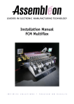
7
MultiFlex PAK E2 Interface
formed in the Controller Setup screen. To access
this screen:
E2
The MultiFlex PAK is capable of communicating with an E2 RX refrigeration controller
version 2.10 and above, or an Einstein RX
refrigeration controller with software version
1.83 or above.
In order to take advantage of new E2 and
PAK features such as Danfoss EKC514 integration, the E2 must be version 2.60 or above. The
Einstein RX and E2 versions before 2.60 do not
support Danfoss EKC514 or some of the
advanced features of suction float.
1. Log in to the E2.
2. Press I
to access the System Configuration
Menu.
3. Press - Network Status/Setup
4. Press - Connected I/O Boards & Controllers.
5. Enter the number of PAK boards that will be networked
with this E2 in the PAK Controllers field.
Using MultiFlex PAK boards with a central
Einstein controller offers several benefits over
simple stand-alone PAK control, including:
•
•
•
Reporting of PAK-related alarms in the
Alarm Advisory Log
The ability to log PAK inputs in an E2 logging group
Remote access to PAK status and programming from the E2 front panel or remote communication tools (InSite or UltraSite32).
Communication between E2 and a PAK
takes place over the RS485 I/O Network. Follow
the instructions in Section 3, The I/O Network,
to connect the PAKs to the E2 I/O network.
Then, follow the instructions in this chapter to
set up the PAKs.
7.1.
Adding/Deleting a PAK
Figure 7-1 - Controller Setup Screen
NOTE: Unlike other MultiFlex board types,
the PAK will NOT automatically show as
"Online" in the Online Status screen. You must
first set the "Connected" parameter in the PAK
application to "Yes." See Section 7.2., Setting
the "Connected" and "Read Setpoints" Attributes.
7.1.1. Adding a PAK
Before an E2 will communicate with a PAK,
it must be added as an I/O board. This task is per-
24 • MultiFlex I/O Board Operator’s Guide
026-1722 Rev 4 03-JUN-2010
7.1.2. Deleting a PAK
To remove a PAK from the E2:
E2
1. Log in to the E2.
2. Press I
to access the System Configuration
Menu.
3. Press - Network Status/Setup
4. Press - Connected I/O Boards & Controllers.
5. Change the number of PAK boards in the PAK Controllers field to the correct number of boards.
will appear prompting you to select a single
PAK. Use the arrow keys to highlight the
PAK you wish to view, and press >.
3. Press E - SETUP.
4. Use the arrow keys to highlight the "Connected" field. Press Y to set this field to Yes.
5. If you want the E2 to read the setpoints from
the PAK and write them to the E2 upon connection, set the "Read Setpoints" field to
Yes.
When PAKs are deleted in this way, E2 will
always delete the highest numbered PAKs first.
Therefore, if you have seven PAKs (numbered 17) and you change the number of PAKs to five,
the E2 will delete board #6 and #7, leaving
boards #1 through #5.
7.2.
Setting the "Connected"
and "Read Setpoints" Attributes
Unlike other MultiFlex devices, the PAK
will not automatically communicate with the E2
once the board is properly numbered and added
in the Connected I/O screen. To enable communication with the PAK, you must set the "Connected" parameter in the General tab of the PAK
setup screens to "Yes." By default, a new PAK
added to the E2 will have the "Connected"
parameter set to "No."
The PAK also has a feature called Read Setpoints, which allows contractors who configure
the PAK via Hand-Held Terminal before connection to an E2 to have the PAK setpoints saved to
the E2 upon initial connection.
1. Press I (Configured Applications).
6. Press J to save changes and return to
the Status Screen.
The E2 will attempt to establish connection
with the PAK. If the Read Setpoints field was set
to Yes, the E2 will read the setpoints from the
PAK and write them to the PAK application’s
configuration. If Read Setpoints is set to No, the
E2 will write the PAK application’s setpoints to
the PAK upon initial connection.
7.2.1. Verifying Online Status
If you have properly set up the MultiFlex
PAK board on this E2’s I/O Network, after setting the Connected parameter, you can go view
the status of the I/O Network (press
I
- Online Status). If E2 and the
PAK boards are communicating, this screen will
show the PAK board as “Online.” If not, it will
be shown as "Offline."
2. Select item "187. MultiFlex PAK". If multiple PAKs are associated with this E2, a list
Setting the "Connected" and "Read Setpoints" Attributes
MultiFlex PAK E2 Interface • 25
All PAK boards whose associated E2 applications have their "Connected" parameters set to
No will be shown in this screen as status
"Unknown."
7.3.
Viewing the PAK Status
Screen
Once you have added a PAK to the E2, you
will be able to see the status of the PAK board(s)
from the front panel.
E2
1. Press I (Configured Applications).
2. Select item "187. MultiFlex PAK"
If multiple PAKs are associated with this E2, a list will
appear prompting you to select a single PAK. Use the arrow keys to highlight the PAK you wish to view, and
press >.
The PAK Status Screen for the PAK you selected will appear (Figure 7-2).
7.3.1. Inputs and Set Points
The top four lines of the PAK Status Screen
show the current values of all the important
inputs and set points in the PAK controller.
Suct
The Suct field shows the current value of the
suction pressure. The value shown in smaller
type to the right of the suction pressure field
(enclosed by brackets [ ]) is the suction pressure
control set point, displayed here for reference
purposes.
TD
The TD field shows the current calculated
value of the temperature differential between the
discharge temperature and the ambient temperature. The value shown in smaller type to the right
of the TD field (enclosed by brackets [ ]) is the
TD set point, displayed here for reference purposes.
Suction Temp
This field shows the value of the PAK’s suction return gas temperature input.
Liquid Level
This field shows the value of the PAK’s liquid level input.
Comp Amps
This field shows the value of the PAK’s
Compressor Amps input.
Cond Temp
This field shows the condenser discharge
temperature calculated by converting the discharge pressure to temperature based on the system refrigerant.
Amb Temp 1
Figure 7-2 - PAK Status Screen
The PAK Status Screen shows the current status of all compressors and condensers. Though
there is a large amount of information on a PAK
status screen, status information is grouped on
this screen in several groups of related information in order to make the screen easier to read.
These groups are described below.
26 • MultiFlex I/O Board Operator’s Guide
The Amb Temp 1 field shows the current
value of the ambient temperature sensor on the
condenser.
Disch
This field shows the current value of the discharge pressure transducer.
Cond Amps
This field shows the current value of the
PAK’s Condenser Amps input.
026-1722 Rev 4 03-JUN-2010
7.3.2. Compressor Groups
•
The box left of the middle of the PAK Status
Screen shows the current status of the compressor groups defined for the PAK.
Fixed Step
Compressor Group HP/AMPS and Status
Each group from 1 through 8 has a field
showing HP/AMPS, which displays the total
amount of HP or AMPS of all compressors associated with the group, and a Status field, which
shows whether the group is currently ON or
OFF.
COMP Mode
The Compressor Group Mode field explains
the current state of the fixed step control algorithm in the MultiFlex PAK. There are seven
messages that may appear here:
•
•
•
•
•
•
OFF - No compressor groups are ON, and
none are being called to be ON.
Off Delay - The MultiFlex PAK requires less
compressor HP/AMPS, and is trying to cycle
backward through the fixed steps, but PAK is
currently waiting for the fixed step OFF
delay to elapse before moving to the next
lower step.
On Delay - The MultiFlex PAK requires
more compressor HP/AMPS, and is trying to
cycle forward through the fixed steps, but
PAK is currently waiting for the fixed step
ON delay to elapse before moving to the
next higher step.
DeadBand - The suction pressure is within
the set point dead band. The PAK will
remain on the current fixed step and is not
attempting to move up or down to a new
step.
Max Cap - The PAK has cycled through the
fixed steps all the way to the last step, but the
set point is still out of range. In other words,
the PAK would activate more HP/AMPS if
more were available, but it is operating at
maximum capacity.
XDucer Fail - The suction pressure transducer input has failed.
Viewing the PAK Status Screen
Disch Trip - The discharge pressure has
exceeded the discharge trip setpoint, causing
the compressor group to shut down.
This field shows the number of the currently
active fixed step.
7.3.3. Compressor Status
Because compressor group stages may contain more than one compressor, the center box
shows the status of each individual compressor
in the PAK, along with the compressor group
number assignment.
7.3.4. Condenser Fans
The right side of the PAK Status Screen
shows the current status of the condenser fans.
Fan Stages 1 through 4
If the condenser is using single-speed fan
stages (either by using "Staged Fans" strategy to
control the fan stage relays OR by using "Fan
Sequencer" to control the fan stages through an
analog sequencer), the status of each fan stage
from 1 through 4 will be shown in a box on the
right side of the screen.
VS Fan Status
If the condenser is using variable-speed fans,
the VS % and the state of the VSD Enable relay
will be shown on the right side of the screen. A
VS Fault status will also be shown, which will
display "ON" if the inverter has failed.
Cond Mode
The Condenser Mode field explains the current state of the condenser fan control algorithm
in the MultiFlex PAK. There are seven messages
that may appear here:
•
•
OFF - All condenser fans are OFF, and the
discharge pressure/temperature is low
enough to not require any fans to be activated.
OFF Delay - The PAK is calling for fan
stages to deactivate, and PAK is waiting for
the OFF Delay time period to elapse before
deactivating the next fan stage.
MultiFlex PAK E2 Interface • 27
•
•
•
•
ON Delay - The PAK is calling for fan stages
to activate, and PAK is waiting for the ON
Delay time period to elapse before activating
the next fan stage.
DeadBand - The discharge pressure is within
the setpoint deadband, and therefore the PAK
is neither activating nor deactivating any fan
stages.
Max Cap - All condenser fans are ON, but
the discharge pressure is still above set point.
In other words, PAK would activate more fan
stages if more were available, but it is operating at maximum capacity.
Cond Spray - The condenser spray output is
currently ON, meaning the discharge pressure is currently higher than the condenser
spray set point.
Each setup screen contains a number of
fields used to program the PAK or the E2 interface to the PAK. For descriptions of each field,
highlight the field value using the arrow keys,
then press F (HELP) to read the on-line help.
7.4.1. Screen 1: General
7.3.5. Connected and PAK State
At the very bottom of the PAK Status Screen,
the "Connected" field shows the state of the PAK
application’s "Connected" parameter, thus showing whether the PAK has been enabled for communication. "Connected" means the Connected
parameter is set to Yes; "Not Connected" means
the parameter is set to No.
The "PAK State" field shows whether the
MultiFlex PAK is currently reading as Online or
Offline.
Figure 7-3 - PAK Screen 1: General
In the General screen, enter a name for the
PAK application, specify the temperature and
pressure units you will be using, and enter the
number of compressors and condenser fans.
7.4.2. Screen 2: Comp Setpts
Note that a status of "Connected" in the Connected field does not necessarily mean the PAK
is communicating with the E2 - if the PAK State
reads "Offline,"
7.4.
Programming the PAK
using E2
To begin programming a PAK, navigate to
the PAK Status Screen for the board you wish to
program (see Section 7.3.). For E2, press E
to enter the Setup Editor.
28 • MultiFlex I/O Board Operator’s Guide
Figure 7-4 - PAK Screen 2: Compressor Setpoints
The Compressor Setpoints screen is where
you must enter the suction pressure setpoint and
deadband, as well as assign each compressor to a
compressor group.
026-1722 Rev 4 03-JUN-2010
7.4.3. Screen 3: Cond Setpts
The Float Case input definitions are where
you must define each circuit’s case temp value.
As long as the source of the case temp value is a
Danfoss EKC514, DFMC, Woodley case controller, EC2 case controller, or E2 Standard Circuit application, the E2 will automatically read
the controller or application’s case state (refrigeration, defrost, etc.) and consider the case state
when determining whether or not to exclude the
case’s temperature from the suction float temperature combination.
7.4.5. Screen 5: PAK Inputs
Figure 7-5 - PAK Screen 3: Condenser Setpoints
The Condenser Setpoints screen is where
you must enter the discharge pressure setpoint
and deadband, as well as setpoints that determine the TD calculation and operation of other
condenser systems such as the condenser spray.
Condenser fans are also assigned to condenser fan groups (outputs) in this screen.
7.4.4. Screen 4: Float Setup
Figure 7-7 - PAK Screen 5: PAK Inputs
The PAK Inputs screen is where you must
assign each of the 16 PAK inputs to an input
type. Other setpoints on this screen control how
certain inputs are read (such as liquid level sensors, CTs, and the suction transducer).
Figure 7-6 - PAK Screen 4: Float Setup Setpoints
The Float Setup screen is where setpoints
and case temperature inputs for the Suction Float
feature are configured. This screen is not visible
unless the Enable SP Float parameter on Screen
1 is set to "Yes."
Programming the PAK using E2
MultiFlex PAK E2 Interface • 29
7.4.6. Screen 6: Outputs
7.4.8. Screen 8: Fixed Steps
Figure 7-8 - Screen 6: Outputs
Figure 7-10 - PAK Screen 8: Fixed Steps
The Outputs screen of the E2 PAK application provides output definitions that may be used
to connect PAK outputs to inputs of other applications for use in extended I/O control. No user
programming is required in this screen when
programming the PAK.
The number of steps that appear on this
screen is determined by the number entered in
the "Number of Steps" field in Screen 1.
7.4.7. Screen 7: PAK Outputs
For each step, specify which compressor
groups will be active by changing the field in the
numbered column representing the group number to "X." Inactive compressor groups must
have a "-" in the group number field. Use the ;
and 2 keys to toggle the field value.
Refer to Section , Example of Fixed steps,
for more information about setting up fixed
steps.
Figure 7-9 - PAK Screen 7: PAK Outputs
The PAK Outputs screen is where you must
assign the functions of each of the eight relay
outputs and four analog/digital outputs on the
MultiFlex PAK.
30 • MultiFlex I/O Board Operator’s Guide
026-1722 Rev 4 03-JUN-2010
7.4.9. Screen 9: Safety
Figure 7-11 - PAK Screen 9: Safety
The Safety screen is used to set up various
safety shutdown features for the PAK such as
discharge trip and suction temperature trip.
7.4.10.Screen B: Alarms
Figure 7-12 - PAK Screen B: Alarms
This screen is under the "MORE" tab at the
top of the screen, and is accessible by pressing
4+ and then selecting )-Alarms.
This screen is where you specify what type
of advisories you want the E2’s PAK application
to generate when failures occur. You may choose
advisory types, setpoints, priorities, and delays
for most alarm types generated by the PAK.
Programming the PAK using E2
MultiFlex PAK E2 Interface • 31
8
MultiFlex PAK HandHeld Terminal Interface
and analog outputs (both in volts and in percentage)
• Override relay outputs to a fixed ON or OFF state,
or override analog outputs to a fixed percentage
• Make temporary or permanent changes to set points
Plugging In the Hand-Held Terminal
All MultiFlex boards have a Hand-Held Terminal interface, which can be used to view status
for the board without having to use the site controller. Though different for each model of MultiFlex, the Hand-Held Terminal interface allows
you to perform the same general functions:
• View failure messages that relate to the MultiFlex
• View the status of inputs
The Hand-Held Terminal plugs into the RJ11
jack on the MultiFlex base board (located on the
bottom left side of the board, as shown in Figure
8-1). Press the Hand-Held Terminal connector
into the jack until it snaps into place. When the
connector is correctly seated, the screen to the
Hand-Held Terminal will display the message
“CPC Handheld Terminal” and then the first
screen of the MultiFlex interface.
• View the current state of relay outputs (ON or OFF)
Figure 8-1 - MultiFlex HHT Jack Location
Shortcut Keys (F1 and F2)
8.1.
The HHT Interface
8.1.1. Navigation
At any time, you may press the F1 key on the
Hand-Held Terminal to return to the Configuration Menu, or F2 to view the status screens.
The Hand-Held Terminal interface consists
of a simple series of screens and menus.
Scrolling Through The Hand-Held Screens
The UP ARROW and DOWN ARROW
keys are used to scroll through the screens. Some
of these screens are read-only, meaning there are
no editable fields; others are either menus that
require you to enter a selection or are configuration screens that have one or more changeable
fields.
32 • MultiFlex I/O Board Operator’s Guide
026-1722 Rev 4 03-JUN-2010
8.2.
PAK Start Screens
MULTIFLEX PAK
810-3082
VER: 2.50F01
( PRESS
)
When the HHT is plugged into the MultiFlex
board, the HHT display will show the model
type of the MultiFlex (PAK), the CPC part number, and the firmware revision.
DIP Settings:
Address: 1
Baud
: 9600
Pressing the DOWN ARROW key from the
start screen displays the address and baud rate
settings as read from the MultiFlex’s addressing
and baud rate DIP switches.
From the DIP Settings screen, pressing the
DOWN ARROW key again will select the first
PAK status screen. You will not be able to view
the start screen or the DIP Settings screen again
without disconnecting and reconnecting the
HHT.
8.3.
PAK Status Screens
The eleven PAK Status Screens show the
current readings of all PAK inputs, the states of
all outputs and proofs, and other operating information.
By default, the HHT automatically scrolls
through the screens in sequence every 3 seconds.
To freeze the display on the current screen, press
the POINT "." button on the HHT. In this mode,
you can use the UP ARROW and DOWN
ARROW keys to scroll through the status
screens.
8.3.1. Status Screen 1
Pressure(hold=.)
Suction
34.0
Discharge 99.4
Amb 1 Temp 17.7
Suction. The current value of the suction pressure input.
Discharge. The current value of the discharge
pressure input.
Amb 1 Temp. The current value of ambient
temperature sensor #1.
8.3.2. Status Screen 2
Comp Disch Temps
#1 (1 to 8) #4
21 50 45 45
OPE OPE OPE OPE
This screen shows the current values of compressor discharge temperature inputs #1 through
#8. The third line of the display shows inputs #1
through #4 from left to right, and the fourth line
of the display shows inputs #5 through #8 from
left to right.
If a sensor input is unused, disconnected, or
there is a break in the wire, "OPE" will be shown
to indicate an open input. If a sensor input is
shorted, its value will be shown as "SHO."
8.3.3. Status Screen 3
Cond TD 11.0
Amb 2 Temp OPEN
Cond Temp 74.1
Disch Pres 99.4
Cond TD. The Cond TD is calculated by subtracting the ambient temperature from the condenser’s discharge temperature (calculated by
converting the discharge pressure to temperature). The Cond TD is compared to the PAK’s
Condenser TD setpoint when controlling the
fans.
Amb 2 Temp. The current value of the Ambient
Temp sensor #2 (or OPEN if this sensor input is
unused).
PAK Start Screens
MultiFlex PAK Hand-Held Terminal Interface • 33
Cond Temp. The Cond Temp is the condenser
discharge temperature, calculated by converting
the discharge pressure input value to a temperature.
Disch Press. The current value of the discharge
pressure input. This is the same value as shown
in Status Screen 1, only repeated here for easier
comparison to the other values on this screen.
8.3.4. Status Screen 4
Suct Pres 34.0
DB/SP 4.0 /45.0
Comp
12345678
Groups
00 0000
Suct Pres. The current value of the suction pressure input. This is the same value as shown in
Status Screen 1, only repeated here for easier
comparison to other values on this screen.
DB / SP. The number to the left of the slash is
the programmed deadband value around the suction setpoint. The number to the right of the
slash is the programmed suction setpoint.
Comp Groups. The fourth line of the display
shows the current state of each of the compressor group on the PAK. The characters shown
here, numbered 1 through 8, will be "|" when the
compressor group is active, and "0" when the
compressor group is inactive. Unused groups
will also be shown as "0."
8.3.5. Status Screen 5
Cond TD 12.1
DB/SP 4.4 /8.3
Cond
12345678
Fans
000000
Cond TD. The Cond TD is calculated by subtracting the ambient temperature from the condenser’s discharge temperature (calculated by
converting the discharge pressure to temperature). This is the same value as shown in Status
Screen 3, only repeated here for easier comparison to the other values on this screen.
34 • MultiFlex I/O Board Operator’s Guide
DB / SP. The number to the left of the slash is
the programmed deadband value around the condenser TD setpoint. The number to the right of
the slash is the programmed condenser TD setpoint.
Cond Fans. The fourth line of the display shows
the current state of each of the condenser fan
groups (corresponding to the fan group outputs
on the PAK). The characters shown here, numbered 1 through 8, will be "|" when the fan group
output is active, and "0" when the fan group output is inactive. Unused outputs will also be
shown as "0."
8.3.6. Status Screen 6
Cond Temp 74.1
DB/SP 4.4 /8.3
VSD 0.0 % En OFF
0.0V
Fault OFF
Cond Temp. The Cond Temp is the condenser
discharge temperature, calculated by converting
the discharge pressure input value to a temperature.
DB / SP. The number to the left of the slash is
the programmed deadband value around the current condensing temperature setpoint. The number to the right of the slash is the condensing
temp setpoint, which is calculated by adding the
programmed condenser TD setpoint to the ambient temp used for control.
VSD. The current operating speed of the VSD,
represented as a percentage of its maximum
speed.
En. The current state of the VSD Enable relay,
which is ON when the VS Fan is called to be ON
and OFF when the VS Fan is called to be OFF.
V. The voltage value shown directly below the
VSD field is the current output voltage of the
PAK analog output controlling the VS Fan.
Fault. The current state of the VSD Fault input.
026-1722 Rev 4 03-JUN-2010
8.3.7. Status Screen 7
Suct Temp OPEN
Comp Amps NDF
Cond Amps NDF
Liq Level 37.0
8.3.9. Status Screen 9
12345678<Fans
0000
1234567<Comps>16
000 00 0000000
Suct Temp. The current value of the suction
temperature input value, or OPEN if unused.
This screen shows the current state of individual condenser fans (#1 through #8) and compressors (#1 through #16), NOT THE GROUPS.
When a fan or compressor group is active, the
fans or compressors that are associated with that
group will be shown here as "|". When inactive
or not used, the fans or compressors will be
shown as "0".
Comp Amps. The value of the current transducer measuring amperage used by the compressor pack. If unused, the value will be "NDF."
Cond Amps. The value of the current transducer
measuring amperage used by the condenser fans.
If unused, the value will be "NDF."
Liq Level. The current value of the liquid level
probe, or "NDF" if unused. If the liquid level
sensor is digital, the value will read OK or
NotOK.
8.3.8. Status Screen 8
QuietMode En
Cond Spray
Liqid Inject
Alarm
OFF
OFF
ON
OFF
QuietMode EN. If Quiet Mode is currently
enabled, the status will read ON. If Quiet Mode
is disabled or not being used, the status will read
OFF.
Cond Spray. The state of the Condenser Spray
output.
Liquid Inject. The state of the Liquid Inject output.
Alarm. If an output is set up as type "Alarm,"
this shows the state of that output, which is ON
whenever an alarm is active on the PAK, and
OFF when no alarms are active. If no output is
set up, the value shown here will still be ON or
OFF depending on whether or not alarms are
active.
PAK Status Screens
8.3.10.Status Screen 10
Comp Proof Stats
12345678<Groups
00000000<Fail( )
00000000<Alarm
This screen shows the proof failure status
and alarm status of each of the eight compressor
groups. Line three of the display shows failures;
line four shows alarms. If a proof failure or
alarm is active for a compressor group, the display will show "|" in the column under the compressor’s group number. Otherwise, the display
will show "0".
8.3.11.Status Screen 11
[Modes]
Comp: OFF
Cond: ON Delay
Suct Float: OFF
Comp. The Compressor Group Mode field
explains the current state of the control algorithm in the MultiFlex PAK. There are seven
messages that may appear here:
•
•
OFF - No compressor groups are ON, and
none are being called to be ON.
Off Delay - The MultiFlex PAK requires less
compressor HP/AMPS, but PAK is currently
waiting for the Step OFF delay to elapse
before decreasing capacity.
MultiFlex PAK Hand-Held Terminal Interface • 35
•
•
•
•
•
•
On Delay - The MultiFlex PAK requires
more compressor HP/AMPS, but PAK is currently waiting for the Step ON delay to
elapse before increasing capacity.
DeadBand - The suction pressure is within
the Suction Deadband. The PAK will continue operating at the current capacity.
Max Cap - Based on the current value of the
suction pressure, the PAK would activate
more HP/AMPS if more were available, but
it is operating at maximum capacity.
XDucer Fail - The suction pressure transducer input has failed.
Disch Trip - The discharge pressure has
exceeded the discharge trip setpoint, causing
the compressor group to shut down.
OutDB Delay - Due to the Suction Outer
Deadband feature, the PAK has skipped a
compressor stage change because it determined the suction pressure was returning to
within the Suction Deadband.
Cond. The Condenser Mode field explains the
current state of the condenser fan control algorithm in the MultiFlex PAK. There are seven
messages that may appear here:
•
•
•
•
•
OFF - All condenser fans are OFF, and the
discharge pressure/temperature is low
enough to not require any fans to be activated.
OFF Delay - The PAK is calling for fan
stages to deactivate, and PAK is waiting for
the OFF Delay time period to elapse before
deactivating the next fan stage.
ON Delay - The PAK is calling for fan stages
to activate, and PAK is waiting for the ON
Delay time period to elapse before activating
the next fan stage.
DeadBand - The TD is within the setpoint
deadband, and therefore the PAK is neither
activating nor deactivating any fan stages.
Max Cap - All condenser fans are ON, but
the TD is still above set point. In other
words, PAK would activate more fan stages
if more were available, but it is operating at
maximum capacity.
36 • MultiFlex I/O Board Operator’s Guide
•
•
Quiet Max - Same as Max Cap (see above),
except Quiet Mode is currently active and
the PAK is operating the VS fan at the maximum speed allowed by the Quiet Mode %
setpoint.
Cond Spray - The condenser spray output is
currently ON.
Suct Float. If the PAK is currently enabling suction float to occur, the display will show "ON" in
this field. Otherwise, if suction float is not
active, the display will show "OFF."
8.4.
PAK Configuration
Screens
Some (but not all) of the configuration of the
MultiFlex PAK may be changed using the HHT.
HHT users may change setpoints, redefine input
and output type assignments, and override relays
or analog/digital outputs.
HHT Changes When PAK is Connected to E2
All changes to setpoints made by the HHT
are temporary if the PAK is connected to a parent E2. Changes made in the HHT do not change
the configuration stored in the E2. When the
HHT is unplugged from the PAK, all changes
made by the HHT are overwritten by the E2,
including output overrides. If you wish to make
permanent changes to the MultiFlex PAK’s configuration, you must make them through the E2
(or through a remote communication program
connected to the E2, such as UltraSite32).
HHT Changes When PAK is Stand-Alone
If the MultiFlex PAK is operating standalone with no connection to an E2, the HHT is
the only method that may be used to change configuration. When the HHT is unplugged from the
PAK, all changes to configuration will be saved.
Overrides made with the HHT, however, will be
cancelled when the HHT is unplugged.
026-1722 Rev 4 03-JUN-2010
8.4.1. The PAK Configuration
Menu
1-Gen
2-CompSP
3-Outs 4-CondSP
5-Input 6-Safety
Select: 1
Press F1 at any time to access the PAK Configuration Menu. To select one of the six submenus, press the RIGHT ARROW key, enter the
number of the sub-menu you wish to access,
then press DOWN ARROW key twice to access
the sub-menu’s first screen.
• General - General info about the system the PAK
will control, such as number of compressors and
condenser fans, the control strategy, and more.
• CompSP - Setpoints that determine the operation of
the compressor pack.
Screen 2
Control Strategy
Comp: Cyclic
Cond: StagedFans
Control Strategy Comp. This field determines
the strategy the PAK will follow when activating
and deactivating compressor groups. Refer to
Section 6.1.4., Compressor Control Strategies
for more information.
Control Strategy Cond. This field determines
the strategy the PAK will follow when activating
and deactivating condenser fan groups. Refer to
Section 6.2.1., Condenser Control Strategies for
more information.
Screen 3
Num of Steps: 6
Num of Comps: 10
Num of Cond
Fans: 4
• Outs - Where you select the output type for the relays and analog/digital outputs on the MultiFlex
PAK.
• CondSP - Setpoints that determine the operation of
the condenser.
• Input - Where you select the input type for the sixteen inputs on the MultiFlex PAK.
• Safety - Setpoints that determine the operating conditions for safety shutdowns.
8.4.1.1.
1 - General
Screen 1
PAK Name
:PAK001
Flash
2
Name. Enter a name for the PAK in this field.
Use the LEFT ARROW and RIGHT ARROW
key to move the cursor across the name field.
Use the UP ARROW and DOWN ARROW to
scroll through the list of alphanumeric characters
for each letter or number in the name field.
When finished, press the DOWN ARROW key.
Flash. This read-only field shows the number of
times the flash memory has been rewritten.
PAK Configuration Screens
Num of Steps. If using a Fixed Steps compressor control strategy, enter the total number of
steps in this field.
Num of Comps. Enter the total number of individual compressors (not compressor groups) in
this field.
Num of Fans. Enter the total number of singlespeed fan stages (not fan groups) in this field.
Screen 4
PresUnits: PSI
TempUnits: Deg C
RefrType: R404A
SpecialCode: 0
PresUnits. Choose the engineering unit you
wish to use for all displayed pressure values on
the HHT in the PresUnits field (PSI or KPA, for
kilopascals).
TempUnits. Choose the engineering unit you
wish to use for all displayed temperature values
on the HHT in the TempUnits field (Deg F or
Deg C).
MultiFlex PAK Hand-Held Terminal Interface • 37
RefrType. Choose the refrigerant type used in
the refrigeration system in this field.
SpecialCode. This field is used by ECT personnel for service purposes.
Screen 5
Cond and Comp
InterlockEn: YES
CompProofEn: YES
(4750 Ohms)
Cond and Comp Interlock Enable. When this
parameter is set to YES, the PAK will cycle OFF
condenser fans when no compressors are ON
and the discharge pressure is below the Interlock
setpoint. When this parameter is set to NO, the
Interlock feature is disabled and condenser fans
will be operated separately from compressor
groups.
Comp Proof Enable. If you are using compressor proofing, set this field to YES. Compressor
proofs for the PAK are not separate inputs; they
are resistive loads applied in parallel with the
Discharge Temp sensors for each compressor
group. The PAK interprets changes in the input’s
resistance as proof contact closures or openings.
8.4.1.2.
2 - Comp SP
Screen 1
SuctPresSP: 45.0
OutDB: 8 DB: 4
StepON Dly: 30 S
OFF Dly: 20 S
SuctPresSP. The Suction Pressure Setpoint is
the suction pressure the PAK will attempt to
maintain during compressor pack control (disregarding suction setpoint floating).
OutDB. The Outer Deadband is the range of
pressure values, equally above and below the
Suction Pressure Setpoint but wider than the
Suction Deadband (or DB), within which the
PAK will cancel a compressor group stage
change if the suction pressure is detected as
38 • MultiFlex I/O Board Operator’s Guide
returning to within the Suction Deadband. See
Section 6.1.3., Compressor Group Stage Activation and Deactivation for a complete description
of this feature.
DB. The Deadband is the range of pressure values equally above and below the Suction Pressure Setpoint within which the suction pressure
is considered to be acceptable. While the suction
pressure input value is within this deadband
value, no compressor groups will be activated or
deactivated.
Step ON Delay and Step OFF Delay. The Step
ON Delay is the amount of time the PAK will
wait after the last compressor group activation
before bringing on the next compressor group or
advancing to the next fixed step.
The Step OFF Delay is the amount of time
after the last compressor group deactivation
before deactivating the next compressor group
or moving down one fixed step.
Screen 2
Suct Pressure
Min SP: 0.0
Proof ReStarts
PH: 6 Dly: 240 S
Suct Pressure Min SP. The Suction Pressure
Minimum Setpoint is the lowest allowable suction pressure for the refrigeration system. If the
suction pressure falls below this setpoint, all
compressors will be turned OFF and will remain
off until the suction pressure rises above the Suction Pressure setpoint.
Prf Restart Dly and Proof RestartPH. When a
compressor proof registers a failure, the Proof
Restart Delay is the amount of time the PAK will
wait in between attempts to reset the compressor
proof failure by activating the compressor. The
PAK will try to reset a compressor for a maximum number of times per hour, specified in the
Proof Restart PH field. After the maximum number of retries, if the compressor is still failed, the
PAK will not try any further resets until the start
of the next hour.
026-1722 Rev 4 03-JUN-2010
If a compressor group fails three consecutive
restart attempts, a Proof Fail alarm will be generated.
Screen 3
Comp HP
#1 (1 to
6
6
6
6
or Amps
8) #4
6
6
6
6
The third and fourth lines of this screen contain the eight fields that specify the HP or
amperage rating of compressors #1 through #8.
Line three contains the fields for #1 through #4
(left to right), and line four contains the fields for
#5 through #8 (left to right).
You may enter either the compressor rating
in HP or in amps, provided all compressors controlled by this PAK use the same unit (in other
words, enter all compressors either as HP or as
amps).
Screen 4
Comp HP
#9 (9 to
6
6
0
0
or Amps
16) #12
0
0
0
0
Screen 4 is the same as screen 3, except the
compressor rating fields on this screen are for
compressors #9 through #16.
Screen 5
Comp Output Grps
#1 (1 to 8) #4
0
0
0
0
0
0
0
0
The third and fourth lines of this screen contain the eight fields that specify the compressor
group assignment for compressors #1 through
#8. Line three contains the fields for #1 through
#4 (left to right), and line four contains the fields
for #5 through #8 (left to right).
Screen 6
Comp Output Grps
#9 (9 to 16) #12
0
0
0
0
0
0
0
0
Screen 6 is the same as screen 5, except the
compressor group assignment fields on this
screen are for compressors #9 through #16.
Screens 7-26
Fixed Steps
CompGrp>12345678
Step#1 00000000
HP/Amps:0
The remaining screens under the CompSP
menu option are for users of the Fixed Step
method of compressor group control.
Each screen determines which compressor
groups will be ON or OFF when the fixed step is
active. The eight characters on the third line of
the display signify the states of compressor
groups 1-8. Use the RIGHT ARROW and LEFT
ARROW keys to point the cursor to the character you wish to set, and then use the POINT "."
key or MINUS "-" key to change the character to
either "0" (signifying OFF) or "|" (signifying
ON).
The HP/Amps field on this screen is readonly. It shows for reference purposes the total
amount of compressor HP or amps that will be
ON when this step is active.
When finished, press the DOWN ARROW
key to move to the next screen, and program the
next step. Repeat this process for as many fixed
steps as you defined in Screen 3 under the General menu option. Leave all unused steps set to
all groups OFF (00000000).
For each compressor, specify a compressor
group assignment from 1-8.
PAK Configuration Screens
MultiFlex PAK Hand-Held Terminal Interface • 39
8.4.1.3.
3 - Outs
Screen 5 and 6
Output
R1: NOR
R3: NOR
R5: NOR
Output
R7: NOR
A1: NOR
A3: NOR
Screen 1 and 2
ROut1:
ROut2:
ROut3:
ROut4:
ROut5:
ROut6:
ROut7:
ROut8:
Comp
Comp
Comp
Comp
Comp
Comp
Comp
Comp
Grp1
Grp2
Grp3
Grp4
Grp5
Grp6
Grp7
Grp8
Ovrds
R2: NOR
R4: NOR
R6: NOR
Ovrds
R8: NOR
A2: NOR
A4: NOR
Screens 1 and 2 are used to assign each of
the eight relay outputs on the PAK board to an
output type. Refer to Table 4-3 on page 12 for a
list of output types and their functions.
Screens 5 and 6 are used to override the relay
outputs and analog/digital outputs. The R1
through R8 fields override relays #1 through #8,
and the A1 through A4 fields override analog/
digital outputs #1 through #4.
Note that though the "VSDAnalog" and "Fan
Seq" are selectable output types, these functions
cannot be performed by relay outputs. Do not
assign these two output types to any of the relay
outputs.
To override an output, highlight it with the
cursor and use the POINT "." and MINUS "-"
keys to toggle the field value to either ON or
OFF. To cancel an override, set the field value to
NOR (no override).
Screen 3 and 4
AOut1: FanStage1
ActiveLevel: OFF
AOut2: FanStage2
ActiveLevel: OFF
AOut3: FanStage3
ActiveLevel: OFF
AOut4: FanStage4
ActiveLevel: OFF
Screens 3 and 4 are used to assign each of
the four analog/digital outputs on the PAK board
to an output type. Refer to Table 4-7 on page 14
for a list of analog/digital output types and their
functions.
If you are assigning a digital output type (i.e.
any output type except VSDAnalog or Fan Seq),
you must also specify which state (ON or OFF)
corresponds to "active." When the ActiveLevel
is set to ON, the output will be 0VDC when
inactive and 8VDC when active. When the
ActiveLevel is OFF, the output will be 8VDC
when inactive and 0VDC when active.
40 • MultiFlex I/O Board Operator’s Guide
Overriding A1 through A4 will set the output
to the DC voltage that corresponds to the
selected digital state. This is determined by the
"ActiveLevel" setting for the output (set in
Screens 3 and 4 under the "Outs" menu). In other
words, if the ActiveLevel of the output is OFF,
and you override the output to ON, the voltage
will be 0VDC while in override.
All overrides initiated with the HHT are cancelled when the HHT is unplugged from the
MultiFlex PAK.
Screen 7
Analog Fan Ovrd
Ovrd: NO
Ovrd Volts: 10
Screen 7 is used to override the variablespeed condenser fan output. To initiate an override, set the Ovrd field to "YES," and specify the
desired output voltage in the Ovrd Volts field.
To cancel an override, set the Ovrd field to
"NO." This override is also cancelled when the
HHT is unplugged from the MultiFlex PAK.
026-1722 Rev 4 03-JUN-2010
8.4.1.4.
4 - CondSP
Screen 3
TD Control Fail
Ambient Temp
DiscPresSP: 220
DeadBand: 4.0
Screen 1
Cond TD SP:
DeadBand :
Fan ON Dly:
FanOFF Dly:
8.3
4.4
15 S
45 S
Cond TD STPT and Cond TD DeadBd. The
Cond TD Setpoint is the difference between the
condenser discharge temperature and ambient air
temperature the PAK will attempt to maintain.
When the condenser TD is higher than this setpoint, the PAK will activate fan groups. When
lower than the setpoint, the PAK will deactivate
fan groups.
The Cond TD Deadband is the range of differential values around the Cond TD Setpoint
within which the setpoint is considered satisfied.
When the TD is within the setpoint deadband, no
fan groups will be activated or deactivated.
Fan ON Delay and Fan OFF Delay. The Fan
ON Delay is the amount of time the TD must be
above the Setpoint before turning ON a fan
group. The Fan OFF Delay is the amount of time
the TD must be below the Setpoint before turning OFF a fan group.
Screen 2
TD Control
Pressure Limits
Disch Max: 290
Disch Min: 100
Disch Pres Max. If the discharge pressure rises
above this setpoint, the PAK will override TD
control and stage fan groups ON to bring down
the discharge pressure. The Fan ON Delay will
be observed as each stage is activated.
Disch Pres Min. If the discharge pressure falls
below this setpoint, the PAK will override TD
control and stage fan groups OFF to bring up the
discharge pressure. The Fan OFF Delay will be
observed as each stage is deactivated.
PAK Configuration Screens
Disch Pres SP and Disch Pres DB. The Discharge Pressure Setpoint and the Discharge Pressure Deadband will be used as the fallback
setpoint and deadband if the TD calculation cannot be made due to ambient temperature sensor
failure.
Screen 4
TD Min Ambient
Temp SP: 1.7
DisableInterLock
Disch Pres: 305
TD Min Amb Temp Min SP. The Ambient
Temp Minimum Setpoint is the minimum allowable value of the ambient air temperature used in
the TD calculation. If the ambient air temperature falls below this setpoint, the value of this
setpoint will be used as the substitute ambient air
temperature in the TD calculation.
Disable Interlock Discharge Pressure. When
the discharge pressure rises above the Interlock
Disable setpoint, interlock will be disabled to
prevent fans being locked OFF when needed to
lower the discharge temperature.
Screen 5
CondSpray: 330
AmbLockOut: 24
Rtn2Nrml: 270
Off Delay: 30 M
Cond Spray SP. The Condenser Spray SP controls operation of the condenser spray output. If
the discharge pressure rises above the Condenser
Spray Setpoint, the PAK will activate the Condenser Spray output. The output will remain
active until the discharge pressure falls below
the Rtn2Nrml setpoint and remains there longer
than the Rtn2Nrml Time.
MultiFlex PAK Hand-Held Terminal Interface • 41
Amb Spray Lkout. The Ambient Spray Lockout setpoint is the ambient air temperature below
which the condenser spray output will be locked
OFF.
Rtn2Nrml and Off Delay. The Return To Normal setpoint is the cut-off pressure for the condenser spray. When the pressure falls below this
setpoint and remains there for an amount of time
equal to the Off Delay, the condenser spray output will turn OFF.
Screen 6
Screen 8
VSD Fault Input
ActiveLevel: OFF
VSD Max Output
QuietMode: 100
VSD Fault Active Level. The VSD Fault
Active Level is the input state on the VSD Fault
input that indicates a VS fault. Typically, a VS
fault causes an OPEN input state. If the VS
inverter closes the fault input on failure, change
the value of this field to ON.
Analog Fan Setup
Max Volts: 10.0
MinOnVolts: 2.0
Min On Pct: 20.0
VSD Max Output Quiet Mode. This setpoint
sets the maximum VS fan speed when the PAK
is operating in Quiet Mode.
Fan Max Volts. The Fan Max Volts is the voltage of the analog output that corresponds to the
maximum VS fan speed.
Fan Seq Setup
Step Volts: 1.5
All Off 0 Volts
1st On 2.0 Volts
Fan Min ON Volts. The Fan Min ON Volts is
the voltage of the analog output that corresponds
to the minimum fan speed when the VS fan is
ON.
Fan Min ON Pct. The VS Min ON Pct is the
minimum percentage at which the VS fan will
operate when ON. When switched ON, the VS
fan will begin operating at this percentage.
Screen 7
VSD Fan Setup
Volts/MinuteRate
Increase: 10.0
Decrease: 10.0
Volts/Minute Increase. The VS Increase Voltsper-Minute Rate is the rate, in volts per minute,
that the analog output controlling the VS fan will
increase when a higher fan speed is being called
for.
Screen 9
Screen 9 sets the operating parameters for
the Fan Sequencer output.
The All Off field shown in this screen is
read-only and is fixed at 0V. This signifies 0V
will be the Fan Sequencer output voltage when
all fans are called to be OFF.
The 1st On field shown in this screen is also
read-only and is equal to the value of Fan
MinON Volts in Screen 6. The voltage shown in
this field will be the Fan Sequencer output voltage when stage 1 is called to be ON.
After the first fan stage is ON, the PAK will
increase the voltage of the Fan Sequencer output
by a fixed amount every time a new fan stage is
to be activated. Enter the fixed voltage in the
Step Volts field.
Volts/Minute Decrease. The VS Decrease
Volts-per-Minute Rate is the rate, in volts per
minute, that the analog output controlling the VS
fan will decrease when a lower fan speed is
being called for.
42 • MultiFlex I/O Board Operator’s Guide
026-1722 Rev 4 03-JUN-2010
Screen 10
Fan HP or Amps
#1 (1 to 8) #4
4
4
4
4
0
0
0
0
The third and fourth lines of this screen contain the eight fields that specify the HP or
amperage rating of condenser fans #1 through
#8. Line three contains the fields for #1 through
#4 (left to right), and line four contains the fields
for #5 through #8 (left to right).
You may enter either the fan motor rating in
HP or in amps, provided all fans controlled by
this PAK use the same unit (in other words, enter
all condenser fan motor ratings either as HP or
as amps).
Cond CT Amp Size and Comp CT Amp Size.
The Cond CT Amp Size and Comp CT Amp
Size fields specify the size of the current transducers (in amps) measuring power consumption
for the condenser and compressor pack respectively. The rating entered here should be the current value that corresponds to a 5VDC output
from the current transducer.
LiqDig OK. Choose the digital state of the liquid level sensor that corresponds to "liquid level
OK" in this field. Choose CLSD if the sensor is
CLOSED when the liquid level is OK, or OPEN
if OPEN when OK.
Screen 2
Input Offsets
Suct Pres: 0.0
Disc Pres: 0.0
Amb Temp: 0.0
Screen 11
Fan Output Grps
#1 (1 to 8) #4
1
1
2
2
0
0
0
0
The third and fourth lines of this screen contain the eight fields that specify the condenser
fan group assignment for fans #1 through #8.
Line three contains the fields for #1 through #4
(left to right), and line four contains the fields for
#5 through #8 (left to right).
For each condenser fan, specify a fan group
assignment from 1-8.
8.4.1.5.
5 - Input
Screen 1
SuctXdcr: 100PSI
CompAmps: 200
CondAmps: 30
LiqDig OK: CLSD
Suct XDucr. Specify the size of the suction
pressure transducer being used in this field. You
may choose 100 lb or 200 lb.
PAK Configuration Screens
These three fields are used to offset the values of the Suction Pressure, Discharge Pressure,
and Amb1Temp inputs to correct for sensor inaccuracies. The value entered in an offset field will
be added to the value as read by the sensor.
Screen 3
Liquid Level
Volts
%
Min: 0
0
Max: 5
100
These four fields determine how the PAK
will translate the voltage of the Liquid Level
input into a percentage.
Enter the minimum and maximum voltage of
the sensor output in the Liq Level Min V and Liq
Level Max V fields. Then, enter the percentages
represented by these two voltages in the Liq
Level Min and Liq Level Max fields.
MultiFlex PAK Hand-Held Terminal Interface • 43
Screens 4-19
Input Setup 1
Name: Suct Xdcr
The sixteen Input Setup screens are where
the input types for MultiFlex PAK inputs #1
through #16 must be defined. The input types are
listed and described in Table 4-1 on page 9.
8.4.1.6.
6 - Safety
Screen 1
Safety Shutdowns
HiDisch Pres NO
Reset All: NO
The read-only field "HiDisch Pres" indicates
whether or not a safety shutdown due to high
discharge pressure is active ("YES" indicates an
active shutdown).
If HiDisch Pres is "YES," the safety shutdown may be reset from this screen. Move the
cursor to the Reset All field and press POINT "."
or MINUS "-" to change the value of the field to
"YES."
An automatic reset will only occur if the
PAK has been in safety shutdown for an amount
of time equal to the Reset Delay.
Reset Delay. The Reset Delay is the minimum
amount of time the PAK will remain in safety
shutdown after a discharge trip has occurred.
After the Reset Delay has elapsed, if the discharge pressure lowers to below the Discharge
Trip Setpoint minus the Reset Diff, the safety
shutdown will be reset and the PAK will resume
normal control.
Resets PH. The Resets Per Hour field specifies
the maximum number of automatic resets of a
safety shutdown that will be allowed within a
one-hour period. If a safety shutdown occurs and
the PAK has already auto-reset a number of
times equal to this parameter in the past hour, the
PAK will not attempt another auto-reset and will
remain in safety shutdown for the remainder of
the one-hour period or until the user manually
resets the PAK (see Screen 1 under the "Safety"
sub-menu).
Screen 2
Disch Trip: 340
Reset Diff: 50
Reset Delay: 15M
Resets PH: 5
Disch Trip. The Discharge Trip setpoint is the
discharge pressure value that, if exceeded by the
Discharge Xducer input value, will cause a
safety shutdown of the refrigeration system.
Reset Diff. When a safety shutdown due to discharge trip occurs, the Reset Diff is the amount
the discharge pressure must fall below the Discharge Trip setpoint before the PAK will automatically reset the safety shutdown and resume
normal control. In other words, if the Discharge
Trip setpoint is 340 PSI and the Reset Diff is set
to 50, a safety shutdown will be reset when the
discharge pressure falls below 290 PSI (340 50).
44 • MultiFlex I/O Board Operator’s Guide
026-1722 Rev 4 03-JUN-2010