1
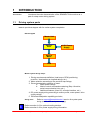
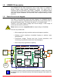
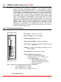
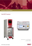
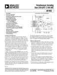
The clever drive
MAN.HESDMWD170 Release 0.2
SDMWD170v _ _ _ _
STEP MOTOR’s
BASIC DRIVE MODULE
USER’S MANUAL
Doc.: HD0380-00-Manual_Sdmwd170Vxxxx_r.0.2_GB.doc-02 24/02/2003
Pag. 1 / 62
IMPORTANT NOTICE
This document is copyrighted by EVER Company. It is supplied to the user with the
understanding that it will mot be reproduced, duplicated, or disclosed in whole or in
part without the express written permission of EVER Company.
EVER co. reserves the right to make changes without further notice to any products
herein to improve reliability, function or design without warning or the obligation of
adjournment of the manufactures and preceding handbooks. EVER co. does not
assume any liability arising out of the application or use of any product or circuit
described herein.
EVER Elettronica
VIA DEL Commercio , 2/4 Loc. S. Grato Z.I.
26900 – LODI - ITALY
Tel. ++39(0)371412318 Fax ++39(0)371412367
E-mail: [email protected]
Web: www.everelettronica.com
EVER Elettronica
Technologiezentrum – Europaplatz
D – 52068 Aachen – GERMANY
Tel. ++49(0)2419631836 Fax ++49(0)2419631835
Ver. Verify
0.1
0.2
0.3
Approval
FA
Printed in LODI - ITALY
Date
24/02/2003
Doc.: HD0380-00-Manual_Sdmwd170Vxxxx_r.0.2_GB.doc-02 24/02/2003
Pag. 2 / 62
SDMWD170
INDEX
1
INTRODUCTION..............................................................................................................5
1.1
Driving system parts....................................................................................................5
1.2
SDMWD170 description..............................................................................................6
1.3
Basic Drive block diagram...........................................................................................6
1.4
Drive use limits, risks and warnings ............................................................................7
1.5
Warranty......................................................................................................................8
1.6
In this manual..............................................................................................................9
2
Specifications.................................................................................................................10
2.1
Mechanical.........................................................................................................10
2.2
Electrical ............................................................................................................11
2.2.1 Power supply ratings..........................................................................................11
2.2.2 I/O electrical specifications ................................................................................11
2.2.3 CAN Bus interface .............................................................................................19
2.2.4 RS232 and RS485 interface ..............................................................................20
3
DRIVE INSTALLATION..................................................................................................21
3.1
Unpacking, Inspecting and Storing ...........................................................................21
3.2
Selecting Motors and Options ...................................................................................21
3.3
User adjustments: Dip-switch settings ......................................................................22
3.4
Installing and Using the Unit Safely ..........................................................................23
3.5
Mounting the Drive ....................................................................................................24
3.6
Connecting to the Drive.............................................................................................26
3.6.1 CN5: Connecting to Earth Ground (EG)....................................................................28
3.6.2 CN5: DC Supply Input (PS).......................................................................................29
3.6.3 CN6: Connecting to Stepper Motor Output (SM).......................................................31
3.6.4 CN3 – CN13: Connecting to drive Inputs ..................................................................33
3.6.5 CN4: Connecting to drive Outputs ............................................................................34
3.6.6 CN2: Connecting to the drive Analog Inputs .............................................................36
3.6.7 CN1: Connecting to CANbus ....................................................................................38
3.6.8 CN1 - CN11: Connecting to RS232 and RS485 interfaces.......................................40
4
STARTING THE SDMWD170 DRIVE............................................................................42
4.1
Testing the Installation ..............................................................................................42
4.2
Maintaining.........................................................................................................42
4.3
Drive operating condition monitoring .................................................................43
4.3.1 Troubleshooting Table .......................................................................................47
5
SDMWD170 VERSIONS AND SPECIFICATIONS .......................................................49
5.1
Drive Coding and Ordering Information ....................................................................49
5.2
Table of SDMWD170Vxxxx available versions .........................................................49
5.3
SDMWD170vB221 Basic Drive (C0300)...................................................................50
5.3.1 Electrical specifications......................................................................................50
5.3.2 Dip switch settings .............................................................................................52
5.4
SDMWD170vB231 Basic Drive (C0400)...................................................................54
5.4.1 Electrical specifications......................................................................................54
5.4.2 Dip switch settings .............................................................................................56
A.1
Factory and user dip-switch setting...........................................................................58
A.2
Power Supply ............................................................................................................60
Doc.: HD0380-00-Manual_Sdmwd170Vxxxx_r.0.2_GB.doc-02 24/02/2003
Pag. 3 / 62
User Notes :
Doc.: HD0380-00-Manual_Sdmwd170Vxxxx_r.0.2_GB.doc-02 24/02/2003
Pag. 4 / 62
1
INTRODUCTION
This section
1.1
introduces the main characteristics of the SDMWD170Vxxxx drive as a
part of a step motor driving system.
Driving system parts
Parts to provide a stepper with for motion system completion
Block diagram
Master Unit
Stepper
Drive
AC/DC Power
Supply
Stepper
Motor
Load
Motion system design steps:
1. Driving requirements definition (load torque, RPM, positioning
precision, acceleration an d speed ratings, etc.);
2. Motor selection according to the previous step ratings;
3. Drive characteristics selection to meet:
a. Motor power ratings
b. Motion control commands mastering (Step / direction,
serial communication links, etc.)
c. Additional features (User I/O, encoder interface, etc.)
4. DC power supply sizing according to motion profile, motor power, drive
supply ratings;
5. Drive heat dissipation capability provision;
Sizing tools
i
Refer to [email protected] service for system parts
sizing (motor, drive and power supply).
Refer to section A.2 for optional cooling devices.
Refer to section A.2 for power supply sizing information.
Doc.: HD0380-00-Manual_Sdmwd170Vxxxx_r.0.2_GB.doc-02 24/02/2003
Pag. 5 / 62
1.2
SDMWD170 description
The SDMWD170 has been designed to drive a step motor in 2 phases on
bipolar chopper mode through step/direction inputs. The basic drive is
compliant with the EN61800-3 and 60204-1 standards. The additional steps
user must take to ensure a complete compliance are: earth connection of drive
and motor, proper installation, ac mains filter, EMC compliant cabling of motor
and drive.
1.3
Basic Drive block diagram
The figure in the following shows the block diagram of a SDMWD170Vxxxx
unit: a step & direction controlled device that can drive a two-phase motor in
the bipolar chopper mode. The motor can have 4, 6 or 8 leads as well.
Thanks to the output stages voltage and current ratings, a wide range of
motors can be driven by the drive.
Motor features must be compatible with the output ratings of the drive.
The drive is provided with:
• Micro-stepping for high resolution and smooth stepper operation;
• Winding current waveforms sinusoidal shaping to optimize motor
performances;
• Over/Under voltage, Thermal and Over Current protections, with
monitoring, to prevent the electronics from damaging.
• Motor steps ramps generation capability
1
MECHANICAL PARTS
1kV
Power
Supply
DC/DC
SUPPLY
DC
EG
PROTECTION
CIRCUITRY
OPTO
ISOLATION
OPTO
ISOLATION
MEG
“A”
BRIDGE
SM
“B”
BRIDGE
Step
Motor
1
i
CONTROL
LOGIC
DIP
SWITCH
Master
Unit
I/O
Serial
link
D
I
S
P
L
A
Y
Max electric strength voltages between drive’s parts
This manual contains mainly information and procedures to install, set-up and
troubleshoot the unit. Several functions of the device depend on the version of
the same.
Doc.: HD0380-00-Manual_Sdmwd170Vxxxx_r.0.2_GB.doc-02 24/02/2003
Pag. 6 / 62
1.4
Drive use limits, risks and warnings
- The planning of the installation must be compliant with the prescriptions in
this manual.
- EVER ELETTRONICA is in no way responsible for damages to persons or to
things caused by an improper use of the equipment.
- The system is actually an internal part of switchboard: it is responsibility of the
planner of the SDMWD170 installation to meet a proper working environment
providing at least the essential duty of the current standard.
- This manual is only for the planner of the SDLWD170 installation and not like
support documentation for user.
Attention
Only qualified
Electro-personnel
Danger
Hazardous Voltages
Hot Surfaces
The installation of the unit as well as of the accessories is only
permissible by qualified personnel. A safe and trouble-free
operation is only possible when the valid regulations according to
EN 60204-1, EN61800-3 as well as the relevant regulations for end
user’s area are observed.
The opening of the drive’s external enclosure is forbidden: inside it
there are parts at high temperature. After any working section, wait
some minutes before operating on the device so that the
temperature of heat sink and the capacitors voltage go down to not
dangerous values. Pay attention to the DC supply and motor
cables connections: when the motor connector is unplugged and
the SDMWD170 is powered dangerous voltages can be present on
motor connector pins.
Making high pot tests on a machine including the SDMWD170 drive, be sure
not to exceed the maximum insulation ratings of the unit.
i
The unit can cause surrounding pollution if removal standard requirements are
not met at casting off.
Doc.: HD0380-00-Manual_Sdmwd170Vxxxx_r.0.2_GB.doc-02 24/02/2003
Pag. 7 / 62
1.5
Warranty
Ever Electronica warrants its motors and controllers to the original purchaser
(end users, original equipment manufacturers or distributors), to be free from
defects in material and workmanship and to be made in accordance with
customer’s specifications which have been accepted in writing with Ever.
Ever Elettronica’s products are warranted for one year from date of
manufacture as determined by the date code on the drive label.
In no event, however, shall EVER be liable or have any responsibility under
such warranty if the product has been improperly stored, installed, used or
maintained, or if the customer allows any unauthorized modifications,
adjustment and/or repairs to such product.
EVER's obligation hereunder is limited solely to repairing ( or replacing at its
option), at its factory any product, or parts, which prove to EVER's satisfaction
to be defective as a result of defective materials or workmanship, in
accordance whit EVER's stated warranty.
The contents of this manual are believed to be correct at the time of printing.
To allow continuous development and improvement of manufactures, EVER
co. reserves the right to change the specifications, characteristics and
performances of the product and the contents of this manual without notice.
EVER co. does not recommend the use of its products in life support
applications wherein a failure or malfunction of the products may directly
threaten life or injury. The user of EVER co. products in life support
applications assumes all risks of such use and indemnifies EVER co. against
all damages.
Doc.: HD0380-00-Manual_Sdmwd170Vxxxx_r.0.2_GB.doc-02 24/02/2003
Pag. 8 / 62
1.6
In this manual
The icons used in this Manual have the following meanings:
i
Danger
Warning
Caution
Used when life or health of the user are exposed
to danger or when severe damage to materials
can occur.
Attention
Special instruction for a safe and trouble-free operation.
Tip
Help
Information
Used to mark additional important information.
An essential element to meet the limit values specified in the EMC directives
is, apart from the use of filters and chokes, the installation of the device
following the EMC standards requirements.
EMC
Doc.: HD0380-00-Manual_Sdmwd170Vxxxx_r.0.2_GB.doc-02 24/02/2003
Pag. 9 / 62
2
Specifications
2.1
Mechanical
Dimensions
Unit: mm
“A” mounting style
i
“B” mounting style
As drive mounting parts the user must be provided with:
•
•
•
•
•
•
•
•
•
•
•
•
•
•
#2 or #4 MA4 screws for unit A or B mounting style;
#1 5-pins 721-605/000-042 WAGO 5mm pitch setting male
connector for motor connection;
#1 4-pins 721-104/026-045 WAGO 5mm pitch setting female
connector for power supply and earth ground connection;
#1 9-pins 1881396 PHOENIX MICRO-COMBICON 2.5mm pitch
setting female connector for Digital Inputs connection;
#1 10-pins 11881406 PHOENIX MICRO-COMBICON 2.5mm
pitch setting female connector for Digital Outputs connection;
#1 4-pins 1881341 PHOENIX MICRO-COMBICON 2.5mm pitch
setting female connector for Digital Outputs connection;
#1 SubD 9-pins female connector for serial link
Dimensions
175(H) x 47.7(W) x 124(D) mm
Weight
1500 g
Protection class
IP 20
Storage temperature
from - 25° C to +55° C
Operating ambient temperature from 5 to 50° C
Humidity
5% to 85% not condensing
Maximum working altitude
1000 m.
Doc.: HD0380-00-Manual_Sdmwd170Vxxxx_r.0.2_GB.doc-02 24/02/2003
Pag. 10 / 62
2.2
i
Electrical
The electrical specifications tolerances, when not differently indicated, are
according to EN 60204 standard requirements.
Some ratings depend on the actual drive version.
2.2.1 Power supply ratings
Refer to section 5.0 for the electrical specifications and voltage ratings of
power supply of the actual drive version.
2.2.2 I/O electrical specifications
Digital Inputs
can be used as real time, opto-isolated, 200kHz, 5Vdc
line driver and 24Vdc PNP/Push-Pull type.
Digtal inputs cannot work at the same time as 5Vdc or 24Vdc
Digital Inputs
Schematic
1
2
+Input
R1
R2
DZ
VCC
R3
2
-Input
D1
4
R4
COM_IN
GND
User I/O:
+Input vs COM_IN => 24Vdc input
+Input vs -Input => 5Vdc Line-Driver
Ratings
3
The line driver inputs are designed to be driven through
devices having the following V-A output characteristic.
Vod - output
differential
Voltage
4,5
DS26LS31CN
4
Vod/0°C
3,5
Vod/25°C
3
Vod/75°C
2,5
100ohm
2
1,5
0
5
10
15
20
25
30
35
40
45
50
Io – output current - mA
Doc.: HD0380-00-Manual_Sdmwd170Vxxxx_r.0.2_GB.doc-02 24/02/2003
Pag. 11 / 62
To prevent input circuitry from improper functioning and damaging do
not exceed the inputs maximum ratings listed in the following table.
Digital Input
Rated
Voltage
Limits
Max.
Min.
Max.
24 Vdc ± 20%
Min.
fMAX
Protection
5 Vdc ± 5%
i
State 0
State 1
UL
IL
UH
IH
V
mA
V
mA
1.5
ND
5
17
0
ND
2
3
ND
ND
19.2
7
ND
ND
28.8
12
200kHz
Against wrong control voltage polarity
The devices connected to the drive inputs must be powered through a
dedicated power supply.
Inputs Electrical
Driving Guidelines
Inputs controlling devices with an output voltage Vo (Volt) exceeding the
Line Driver's ratings must be connected to the basic drive inputs through a
series resistor Rs rated the following way (Vo is assumed greater than 10
Vdc):
RS = [Vo * 125 – 220] Ω with a power rating
2
PD = [(Vo / (RS + 220)) * RS ] W
For instance:
Assuming Vcc = 24Vdc ± 15%
RS = (24 * 125) - 220 ≈ 2780 Ω
2
PD = (24 / (2700 + 220)) * 2700 ≈ 0.18W (0.25W @ Vo+15%)
A 2.7kΩ - ½ W rated external series resistor can be a proper choice.
Assuming Vcc = 12Vdc ± 15%
RS = (12 * 125) - 220 ≈ 1280 Ω
2
PD = (12 / (1200 + 220)) * 1200 ≈ 0.086W (0.12W @ Vo+15%)
A 1.2kΩ - ½ W rated external series resistor can be an effective choice
Doc.: HD0380-00-Manual_Sdmwd170Vxxxx_r.0.2_GB.doc-02 24/02/2003
Pag. 12 / 62
Connection guidelines versus input driving device output style.
PNP source
VCC = 5 Vdc
VCC
PNP source
BD Input
Rs
R1
CNx.x
2
R2
1
DZ
User device
VCC
R3
2
CNx.x
D1
4
R4
COM_IN
GND
3
VCC = 24 Vdc
VCC
BD Input
PNP source
CNx.x
R1
2
R2
1
DZ
User device
VCC
R3
2
CNx.x
D1
COM_IN
R4
4
GND
3
Doc.: HD0380-00-Manual_Sdmwd170Vxxxx_r.0.2_GB.doc-02 24/02/2003
Pag. 13 / 62
NPN sink
VCC = 5 Vdc
VCC
BD Input
R1
CNx.x
R2
2
User device
1
DZ
Rs
NPN sink
VCC
R3
2
CNx.x
D1
4
R4
COM_IN
GND
3
Push-Pull sink
VCC = 5 Vdc
VCC
BD Input
CNx.x
R1
2
R2
1
DZ
Push-pull sink
Rs
VCC
R3
2
CNx.x
D1
COM_IN
User device
Doc.: HD0380-00-Manual_Sdmwd170Vxxxx_r.0.2_GB.doc-02 24/02/2003
R4
4
GND
3
Pag. 14 / 62
Push-Pull source
VCC = 5 Vdc
VCC
BD Input
Rs
R1
CNx.x
R2
1
DZ
Push-pull source
VCC
R3
2
CNx.x
User device
D1
4
R4
COM_IN
GND
3
VCC = 24 Vdc
VCC
BD Input
CNx.x
R1
R2
1
DZ
Push-pull source
2
CNx.x
User device
VCC
R3
D1
COM_IN
R4
4
GND
3
Doc.: HD0380-00-Manual_Sdmwd170Vxxxx_r.0.2_GB.doc-02 24/02/2003
Pag. 15 / 62
Push-pull sink-source
VCC = 5 Vdc
VCC
Complementary Push-pull
(Sink Source)
BD Input
User device
CN1.x
R1
2
R2
1
DZ
VCC
R3
VCC
2
CN1.x
4
1
2
D1
COM_IN
GND
R4
3
- Line-Driver differential 5 Vdc
Line driver
Differential
BD Input
3
CN1.x
2
R1
2
R2
1
DZ
2
CN1.x
D1
User device
VCC
R3
COM_IN
R4
4
GND
3
Doc.: HD0380-00-Manual_Sdmwd170Vxxxx_r.0.2_GB.doc-02 24/02/2003
Pag. 16 / 62
Digital Outputs
are optoisolated, short circuit protected, 24Vdc PNP
type.
Output electrical specification
In (A)
0.5
Rated current (state 1)
Max (A)
0.7
Max current (state 1)
Max current for output
Iout(A)
0,5@24Vdc
with 4 output ON
N° max output ON at
N°
4
max current
Max (V)
3
Voltage drop (state 1)
Max (A)
2
Leakage current (state 0)
Vnom
24Vdc
Rated voltage
Vmin
19Vdc
Min voltage output
Vmax
28.8Vdc
Max voltage output
Vrmax
1Vdc
Max voltage ripple
PNP
current source
Type
f
1kHz
Max frequency output
Short circuit between OUT and GROUND,
between OUT and +V, between OUT and
Protection
OUT, Open Load Detection
Overload & short circuit
> 0.7A min
I (over-current)
= 2.5A max
threshold protection
100µs
Protection intervention
tshortMAX
@Vout = 30Vdc
delay
@RL = 0
1
3
2
4
CN4
Output driver
Doc.: HD0380-00-Manual_Sdmwd170Vxxxx_r.0.2_GB.doc-02 24/02/2003
Pag. 17 / 62
Analog Inputs
+/-10Vdc CEI EN 61131-2 type, not isolated.
CEI EN 61131-2 compliant analog inputs
±10Vdc
Input voltage range
≥10Kohm
Input impedance limits
19.5mV (1024) 10 bit
Reading resolution
Maximum error over full
± 3% of full range
temperature range
Vin = 57Vdc
Maximum overload
Imax = 2mA
Digital output reading under
1024
overload condition
Differential not isolated
Type of input
TSAMPLE = 1ms
Input sampling time
T=1ms
Sampling repetition time
1° order
Input filtering characteristics
Transition frequency: Hz –[email protected]
Resistor-diode and ricirculating network
Protection type
Sample & Hold
Conversion method
Self-scan
Operating mode
Analog
Inputs schematic
VCC
VCC
INAN INAN +
Doc.: HD0380-00-Manual_Sdmwd170Vxxxx_r.0.2_GB.doc-02 24/02/2003
Pag. 18 / 62
2.2.3 CAN Bus interface
Introduction
i
The CAN Bus interface provides a multipoint connection
according to the ISO 11898 standard.
The isolated interface is powered by an internal isolated DC/DC
converter, no external power supply is required.
Refer to section 5 for information about available device’s
versions.
Refer to software manual for information about the can bus
interface operating modes.
Network
connection style
MASTER
UNIT
SDMWD
SDMWD
SDMWD
2
3
n-1
SDMWD
I
1
n
d
L
Doc.: HD0380-00-Manual_Sdmwd170Vxxxx_r.0.2_GB.doc-02 24/02/2003
Pag. 19 / 62
Network paths length
Value
Path
Notation
Unit
Condition
Min.
Nom. Max.
Bus
L
m
0
40
Cable stub
I
m
0
0.3
Node distance
d
m
0.1
40
Bit rate:
1Mbit/sec
Max baudrate [kbit/s] vs bus length
500
< 100 m
250
< 250 m
125
< 500 m
50
< 1000 m
20
< 2500 m
2.2.4 RS232 and RS485 interface
Introduction
i
i
The RS232 interface provide a point to point connection and the
RS485 a multipoint connection (RS485) link according to the
EIA/TIA232E CCIT V.28 and RS-485 CCITT V.11 X.27
international standards.
The isolated interface is powered by an internal isolated DC/DC
converter, no external power supply is required.
Refer to section 5 for more information about available device’s
versions.
Refer to software manual for information about the serial
interfaces operating modes.
2
Cable
Use 0.5 mm² (#20 AWG) or 0.25mm (#23AWG) cross
requirements section leads for the RS232 and RS485 paths cabling.
Doc.: HD0380-00-Manual_Sdmwd170Vxxxx_r.0.2_GB.doc-02 24/02/2003
Pag. 20 / 62
3
DRIVE INSTALLATION
This section
i
explains how to install the step motor drive. Covered topics are:
•
•
•
•
•
•
Unpacking and inspecting the furnishings;
Selecting motor and optional drive’s parts;
Setting user’s adjustments;
Installing and using the unit safely;
Mounting the drive;
Connecting to the drive.
Refer to system diagram in section 1.3.
3.1
Unpacking, Inspecting and Storing
Check
the item(s) against the packing-list. A label located on the drive’s
housing identifies the unit by model version, serial number and
manufacture date.
Inspect the unit: any transportation damages must be submitted by the buyer to
the carrier.
Store
3.2
the SDMWD170 unit in a place meeting the specified conditions.
Selecting Motors and Options
Selecting a motor
The SDMWD170 drive is designed for use with EVER’s
line of step motors or most other brands two phases
step motors. The motor’s ratings must be compatible
with the output configuration and ratings of the drive.
Refer to the Torque/Speed Curves in the “EVER
ELETTRONICA Motors Catalogues” or call EVER sales
dept. or your local distributor for motor sizing and drivemotor compatibility planning.
Selecting Options
Refer to “EVER ELETTRONICA Drives Catalogue” for
drive options planning or call EVER Co. sales dept. or
refer to www.everelettronica.it
Doc.: HD0380-00-Manual_Sdmwd170Vxxxx_r.0.2_GB.doc-02 24/02/2003
Pag. 21 / 62
3.3
User adjustments: Dip-switch settings
Dip-switch
Location
DIP1 and DIP2 are for user adjustments as for instance:
- Bus node identification
- Baud rate setting
- User functioning modes setting
DIP2
ON
1
D1
2
D2
3
D3
4
D4
1
2
D1
D2
3
D3
4
D4
5
D5
6
D6
7
D7
8
D8
DIP1
Some parts inside the SDMWD170 housing can be a potential source of
electric shock.
To avoid electric shock, prior to DIP-SWITCH handling, switch power off
and wait until all the leds of 7 segment display on drive front panel are off.
i
Refer to section 5 for dip-switch function tables in your unit version.
Doc.: HD0380-00-Manual_Sdmwd170Vxxxx_r.0.2_GB.doc-02 24/02/2003
Pag. 22 / 62
3.4
Installing and Using the Unit Safely
Guidelines Only qualified personnel should install the SDMWD170 unit, after first
completely reading and understanding the information in this manual. The
installation instructions should be followed and approved. Any question or
doubt should be clarified with the supplier of the drive before its use.
i
In no event will EVER co. accept liability for indirect or consequential
damage and consequences resulting from inappropriate, negligent or
incorrect installation or modification of the drive or from any incorrect
connection to the SDMWD170 drive.
The power supply cables, the motor output cables and some parts of the
SDMWD170 unit are a potential source of severe electric shock. Follow
the safety guidelines to avoid danger.
To avoid possible personal injury whenever you are working with
SDMWD170 unit:
Do not operate the drive without the motor case and the system
enclosure connected to ground;
The protective earth (PE) impedance must conform to the
requirements of local regulations;
Do not make any connections to the system internal circuitry;
Always turn power supply off before making or removing
connections from the unit;
When the power supply fails the drive cannot hold the load: do
not use system if that can result in a dangerous situation;
provide the motor with a suitable blocking device if necessary.
Before handling or operating maintenance actions on the SDMWD170 unit,
be sure the power supply has been switched off.
•
Be careful of the motor connector terminals when disconnected
from the motor. With the motor disconnected and power applied to
the unit, these terminals can have high voltage rise.
•
Do not use software working program stop as safety shutdown.
Always remove power from the drive for a safe shutdown.
•
Take into account the heat dissipation of some parts the
SDMWD170 unit: using the device in heavy application, some
enclosure surfaces can have high temperature rise. Before
unplugging the drive from the installation wait a proper time for its
cooling.
Doc.: HD0380-00-Manual_Sdmwd170Vxxxx_r.0.2_GB.doc-02 24/02/2003
Pag. 23 / 62
3.5
Mounting the Drive
Environment
The drive should be installed in dust, corrosive vapors, gases and
liquids free environment. Avoid environments allowing condensation of
vaporized liquids, including atmospheric moisture.
Installing the drive inside a cabinet, be sure that the air flow openings
or the cabinet cooling system do not allow the internal temperature rise
to exceed the maximum ambient temperature ratings of the device.
Besides above topics any local safety regulations concerning the
installation of motor drives has to be carefully considered while
planning the location of the drive.
Mounting
Guidelines
Your installation should at least meet the following general guidelines:
• Keep vertical orientation of the device;
• Avoid excessive vibration or shock;
• Provide some free space for air flow below and above the
housing.
Cooling
The SDMWD170 unit has surfaces providing the cooling of the internal
circuitry through their heat dissipation capability. Optimize the thermal
flow between the unit cooling surfaces and the ambient according to
the 'worst case’ power dissipated in your application.
Dissipation through
the fixing surface
Dissipation through
a forced air flow
SDMWD170
Cooling surfaces
SDMWD170
Cooling surfaces
Electrical cabinet rear panel
Electrical cabinet rear panel
Doc.: HD0380-00-Manual_Sdmwd170Vxxxx_r.0.2_GB.doc-02 24/02/2003
Pag. 24 / 62
Minimum installation distance
Doc.: HD0380-00-Manual_Sdmwd170Vxxxx_r.0.2_GB.doc-02 24/02/2003
Pag. 25 / 62
3.6
Connecting to the Drive
Introduction
The drive input / output connectors are:
- Earth Ground
- Motor Earth Ground
- DC Supply Input
- Step Motor Output
- Digital Inputs/Outputs
- CAN bus
- RS232 and RS485 Interfaces
EG
MEG
PS
SM
I/O
CAN*
RS*
(*) available on different drive versions
Connectors
location
and coding
CN6: MEG
CN6: SM
CN5: PS
CN5: EG
CN1: Can or RS Link
CN3: Digital Inputs
CN4: Digital Outputs
CN2: Analog Inputs
Cabling through the common wiring practices and grounding / shielding techniques
described in the following sections should satisfy most of the applications.
Optimum protection is provided by twisted and shielded cables and by
separate laying of signal and power lines.
EMC
Non-standard applications, local electrical regulations, special
operating conditions, and system configuration wiring needs have
precedence over the information herein.
Doc.: HD0380-00-Manual_Sdmwd170Vxxxx_r.0.2_GB.doc-02 24/02/2003
Pag. 26 / 62
The Power Supply must be close to the drive to protect it against
inductive-bunched interference voltages. The DC power Supply is
referred to earth ground through a connection between the negative
side of DC power supply and drive’s internal Earth Ground.
Overall drive
Connection
Diagram
A
C
Transformer
EMC Filter
Protections
~ +
L
i
n
e
Twisted
PS
~ EG
PE
RS232/485 or CANbus
comunication
RS
CAN
EG
Inputs/Outputs
I/O
EG
SM
MEG
Step motor
Doc.: HD0380-00-Manual_Sdmwd170Vxxxx_r.0.2_GB.doc-02 24/02/2003
Pag. 27 / 62
3.6.1 CN5: Connecting to Earth Ground (EG)
Earth Ground connection to PE before any other connection is mandatory.
Cable
Use 1.5 mm² (#16 AWG) or heavier wire for EG cable. Moreover EG
Requirements wire cross section must be at least as large as Vdc wires section.
The EG connection must conform to the requirements of local industry
regulations.
Earth Ground
EG terminal mates to a 721-464/001-040 4-pins
female WAGO cable.
Wago 721-104/026-045
4-pin female 5 mm
To main PE connection
Input
VINC
VINL
PE
GND
Pin
CN5.1
CN5.2
CN5.3
CN5.4
to CN5
Description
DC Bus +side power converter
DC Bus +side logic supply
Earth Ground
DC Bus -side
Doc.: HD0380-00-Manual_Sdmwd170Vxxxx_r.0.2_GB.doc-02 24/02/2003
Pag. 28 / 62
3.6.2 CN5: DC Supply Input (PS)
PS connector connects the SDMWD170 drive to DC supply.
Introduction
Power Supply PS connector mates to a 721-464/001-040 4-pins
male WAGO cable connector.
Input
VINC
VINL
PE
GND
Pin
CN5.1
CN5.2
CN5.3
CN5.4
Description
DC Bus +side power converter
DC Bus +side logic supply
Earth Ground
DC Bus -side
VINL provides the drive controlling logic with DC power supply when the
main unit Power Supply is switched off: if it is not necessary this type of
controlling, VINC provides the complete drive feeding.
The cable to PS links the BD to DC supply line
Wago 721-104/026-045
4-pin female 5 mm
VINC converter
1 VINC
2 VINL
VINL logic
GND
1.5 mm2
(#16 AWG)
To DC supply
4 GND
To CN5
EG and GND are shared to the drive internal circuitry.
Do not solder the tips of the cable before insertion into the connector.
Solder can contract and cause a loose connection over time.
Connection
Diagram
One Axis
Primary AC
voltage
sectioning
EMC Filter
Transformer
A
C
Secondary
AC voltage
sectioning
Protections
Capacitor
Bleeder
resistor
1
~ +
L
i
n
e
PS
~ Twisted
EG
PE
Surge
suppressor
I/O
EG
SM
MEG
1
Provide a 1000uF additional capacitor when DC bus cable is longer than 1mt.
Doc.: HD0380-00-Manual_Sdmwd170Vxxxx_r.0.2_GB.doc-02 24/02/2003
Pag. 29 / 62
Multi Axis
Primary AC
voltage
sectioning Transformer
Twisted
EMC Filter
Secondary
AC voltage
sectioning
PS
1
Bleeder
resistor
EG
I/O
Protections
A
C
SM
~ +
~
~ -
L
i
n
e
PE
Capoacitor
MEG
PS
1
Surge
suppressor
EG
I/O
SM
MEG
1
i
Provide a 1000uF additional capacitor when DC bus cable is longer
than 1mt.
Refer to section A.3 for more information about the power supply
sizing.
Protections
by AC 16A rated fuses on AC bus or by a protection switch.
Sectioning
the ac voltage on primary side is a good safety practice.
The DC supply voltage must never exceed the Vdc rating of your unit
version.
i
Cabling
Requirements
Refer to section 5.0 for more information about the unit version power
supply ratings.
Use 1.5 mm² (#16 AWG) or heavier to make your own power supply
cable
Doc.: HD0380-00-Manual_Sdmwd170Vxxxx_r.0.2_GB.doc-02 24/02/2003
Pag. 30 / 62
3.6.3 CN6: Connecting to Stepper Motor Output (SM)
SM
connector connects the device power stage to motor.
Cabling
Diagram
We suggest to follow the following guidelines while cabling a
motor connection. Always ground the motor case trough a wire
to a specific grounding terminal. Grounding motor case simply
by fixing it to a grounded part of a machine is not a practice
assuring a good impedance of earth ground connecting path.
i
Refer to motor specifications in the motor catalogue to
determine the motor connections as required.
Step Motor
SM connector mates to a 722-235 5-pins female WAGO cable
connector
Pin
CN6.1
CN6.2
CN6.3
CN6.4
CN6.5
Description
Motor phase (B*)
Motor phase (B)
Motor Earth Ground (MEG)
Motor phase (A*)
Motor phase (A)
Cable to SM
Motor Connector
EMI shield
WAGO 721-605/000-042
5-pin 5mm female
connector
B
5
B 4
PE
3
2
Ā 1
A
Step Motor
Grounding wire
EMC
To EG grounding terminal
Paired-twisted cables protect against inductive-bunched
interference voltage. Optimum protection is provided by twisted
and shielded cables and separate laying of signal and power
lines.
Do not solder the tips of the cables before insertion into the
connector. Solder can contract and cause a loose connection
over time.
Doc.: HD0380-00-Manual_Sdmwd170Vxxxx_r.0.2_GB.doc-02 24/02/2003
Pag. 31 / 62
Use #10 to #24 AWG wire.
The following table of cable sizes vs. motor winding current
can be a practical solution:
Cable
Requirements
Motor current (A)
IPHASE ≤ 5 Arms
Cable
2
Section (mm )
1
AWG
18
It’s good practice, when needed, interrupting the motor cable only through
connectors or clamps, isolated from chassis or any mechanical parts, in order
the motor windings, motor’s shielded cable and motor’s protection ground wire
keep well separated. Avoid using switches or circuit breakers on motor phases.
EMI shield
Step Motor
Grounding wire
Doc.: HD0380-00-Manual_Sdmwd170Vxxxx_r.0.2_GB.doc-02 24/02/2003
B
B A
A
To MEG terminal
Pag. 32 / 62
3.6.4 CN3 – CN13: Connecting to drive Inputs
Inputs: optically isolated 5 Vdc Line Driver, PNP, NPN, Push-Pull,
Complementary Push-Pull and 24 Vdc PNP/Push-Pull input terminals are
provided on the CN3 drive edge connector.
Inputs Connector mates to a 1881516 9-pins male PHOENIX MICROCOMBICON cable connector.
Pin
CN3.1
CN3.2
CN3.3
CN3.4
CN3.5
CN3.6
CN3.7
CN3.8
CN3.9
Description
+B0_IN0
-B0_IN0
+B0_IN1
-B0_IN1
+B0_IN2
-B0_IN2
+B0_IN3
-B0_IN3
COM_IN
Functioning
Depending on user’s program
Inputs common (- side)
Refer to section 5.3.3 for inputs/outputs function in a unit version.
i
Cable to I/O
Making the connections to Inputs use a shielded cable with 1 mm² (#18
AWG) or 0.5 mm² (#20 AWG) wires cross section.
9
+B0_IN0
8
7
6
- B0_IN0
+ B0_IN1
- B0_IN1
5
4
3
2
+ B0_IN2
- B0_IN2
+ B0_IN3
- B0_IN3
1
COM_IN
Phoenix micro-combicon
1881396 9-pin female 2.5mm
Using NPN style connection, random input wire grounding can result
in unwanted actuating of the drive.
Doc.: HD0380-00-Manual_Sdmwd170Vxxxx_r.0.2_GB.doc-02 24/02/2003
Pag. 33 / 62
3.6.5 CN4: Connecting to drive Outputs
Outputs are optically isolated 24 Vdc PNP type.
Output Connector mates to a 1881529 10-pins male PHOENIX MICROCOMBICON cable connector.
Pin
CN4.1
CN4.2
CN4.3
CN4.4
CN4.5
CN4.6
CN4.7
CN4.8
CN4.9
CN4.10
i
Description
VSS
B0_OUT0
VSS
B0_OUT1
VSS
B0_OUT2
VSS
B0_OUT3
VSS
+24Vdc
Function
Depending on user’s program
Depending on user’s program
Depending on user’s program
Depending on user’s program
Digital outputs supply - side
Digital outputs supply + side
Refer to section 5.3.3 for inputs/outputs function in a unit version.
Cable to I/O
Making the connections to outputs use a shielded cable with 1 mm² (#18
AWG) or 0.5 mm² (#20 AWG) wires’ cross section.
Phoenix micro-combicon
1881406 10-pin female 2.5mm
10
9
8
+24VDC
VSS
B0 OUT3
7
VSS
6
B0_OUT2
5
4
3
2
1
VSS
B0 OUT1
VSS
B0_OUT0
VSS
Doc.: HD0380-00-Manual_Sdmwd170Vxxxx_r.0.2_GB.doc-02 24/02/2003
Pag. 34 / 62
Outputs schematics and connections
3A rated fuse
CN4.1
+24Vcc
CN4.9
VSS
B1_OUTn
Driver
R
Drive side
VSS
User side
+24Vdc supply is necessary for outputs correct function.
Output protection status is not displayed on the 7 segment display.
Doc.: HD0380-00-Manual_Sdmwd170Vxxxx_r.0.2_GB.doc-02 24/02/2003
Pag. 35 / 62
3.6.6 CN2: Connecting to the drive Analog Inputs
Inputs: not isolated ±10Vdc input terminals are provided on the CN2 drive
edge connector.
Inputs Connector mates to a 1881464 4-pins male PHOENIX MICROCOMBICON cable connector.
Pin
CN2.1
CN2.2
CN2.3
CN2.4
•
i
Description
VPOT=5Vdc
AN_GND
+IN_AN0
-IN_AN0
Function
Voltage supply + side
Voltage supply - side
Depending on user’s program
VPOT=5Vdc: voltage output to supply possible external device connect
to analog input;
Refer to section 5.3.3 for inputs/outputs function in a unit version.
Cable to I/O
Making the connections to outputs use a shielded cable with 1 mm² (#18
AWG) or 0.5 mm² (#20 AWG) wires’ cross section.
Phoenix micro-combicon
1881341 4-pin female 2.5mm
4
3
2
1
Doc.: HD0380-00-Manual_Sdmwd170Vxxxx_r.0.2_GB.doc-02 24/02/2003
-IN AN0
+IN AN0
AGND
VPOT
Pag. 36 / 62
Inputs schematics and connections
Drive Input
VCC
User side
VCC
INAN CN2.4
CN2.3
INAN +
PT
CN2.2
VCC
CN2.1
External potentiometer driven inputs: 5KΩ.
Doc.: HD0380-00-Manual_Sdmwd170Vxxxx_r.0.2_GB.doc-02 24/02/2003
Pag. 37 / 62
3.6.7 CN1: Connecting to CANbus
Can Bus
i
CN1 connector mates to a SUB-D 9-pin male connector.
Refer to drive software manual for CAN bus operating information.
Connections table
Signals
Pin
Functions
N.C.
CN1.1
N.C.
CAN_L
CN1.2
CAN_L signal
0_CAN
CN1.3
Can_ Ground
Reserved
CN1.4
Not used
Reserved
CN1.5
Not used
0_CAN
CN1.6
Optional_Ground
CAN_H
CN1.7
CAN_H signal
Reserved
CN1.8
Not used
N.C.
CN1.9
N.C.
Cable
requirements
2
Use 0.5 mm² (#20AWG) or 0,25mm (#23 AWG)
cross section shielded twisted pair for CANbus
connection.
Pin-Out of the CAN-bus connector
CN1
NC
1
CAN1_L
2
CAN_Ground
3
NC
4
NC
5
6
Optional Ground
7
CAN1_H
8
NC
9
NC
Doc.: HD0380-00-Manual_Sdmwd170Vxxxx_r.0.2_GB.doc-02 24/02/2003
Pag. 38 / 62
CANbus
schematics
For proper can bus working a termination resistor must be inserted between the input
terminals of the first and the last device in the net.
CAN_Ground wiring is optional
SDMW... #2
Master System
CAN_H
CAN_H
120ohm
CAN_L
CAN_Ground
120ohm
CAN_L
CAN_Ground
100ohm
100ohm
100ohm
CAN_H CAN_L CAN_Ground
SDMW... #1
Doc.: HD0380-00-Manual_Sdmwd170Vxxxx_r.0.2_GB.doc-02 24/02/2003
Pag. 39 / 62
3.6.8 CN1 - CN11: Connecting to RS232 and RS485 interfaces.
RS232 and RS485 connector is a 9 pins male SUB-D connector.
i
Refer to drive software manual for serial link operating.
Connections
table
Signals
Pin
Function
N.C.
CN1.1
N.C.
Rx
CN1.2
RS232 receiver input
Tx
CN1.3
RS232 transmitter output
DTR
CN1.4
N.C.
GND
CN1.5
RS232 Interface Signal ground
+Rx
CN1.6
RS485 receiver +side (input)
+Tx
CN1.7
RS485 transmitter +side (output)
-Rx
CN1.8
RS485 receiver –side (input)
-Tx
CN1.9
RS485 transmitter –side (output)
Cable:
requirements Use 0.5 mm² (#20 AWG) or 0.25mm² (#23 AWG) cross section shielded
twisted pair for RS232 and RS485 serial interfaces cabling.
Connector
pin-out
GND
N.C.
TXD
RX
N.C.
5
9
-TX
8
-RX
7
+TX
6
+RX
4
3
2
1
Doc.: HD0380-00-Manual_Sdmwd170Vxxxx_r.0.2_GB.doc-02 24/02/2003
Pag. 40 / 62
RS485 bus schematic
Master System
T
FULL DUPLEX MASTER/SLAVE BUS 4 Wires Net
To / from more
slave terminals
120
R
120
120
T
R
SDMW... #1
T
R
SDMW... #2
T
120
R
SDMW... #3
For proper RS485 net operating two termination resistors must be inserted between the
terminals of the first and the last device in the net
i
The dot led on the drive front panel 7 segment display is lighted while the
RS485 inerface is enabled (connected to the net).
Doc.: HD0380-00-Manual_Sdmwd170Vxxxx_r.0.2_GB.doc-02 24/02/2003
Pag. 41 / 62
4
STARTING THE SDMWD170 DRIVE
This section
explains how to power the SDMWD170 unit after installation. Topics covered
are:
Testing the installation
Maintaining and troubleshooting the SDMWD170 unit
4.1
Testing the Installation
Before first
Powering up
- Check if the device is exactly the version you need (Refer to
section 5.0). Improper DC input voltage or motor current setting could
result in irreparable unit’s or motor’s damages.
- Check that all settings are as you need in your application.
- Check wiring and mounting to verify the proper installation and
integrity of the unit.
First
Power up
Procedure
Perform the first unit powering with the motor shaft disconnected from the
load as improper wiring or undiscovered shipping damages could result in
undesired motor motion.
4.2
Maintaining
Procedure
The SDMWD170 unit is designed for a minimum maintenance.
Remove superficial dust and dirt from the unit using only clean,
dry and low pressure air.
Doc.: HD0380-00-Manual_Sdmwd170Vxxxx_r.0.2_GB.doc-02 24/02/2003
Pag. 42 / 62
4.3
Drive operating condition monitoring
Drive Status
Monitoring
The SDMWD170 actual working condition is monitored on
the 7 segment light emitting diodes (leds) display.
The drive operation modes are displayed as:
“b”
“I”
“S”
“L”
“U”
“E”
“P”
Boot program running: at early drive powering on to
state that the boot program is properly working;
Initialization: the drive is running the start-up
procedure (for about 6 seconds from drive firmware
working start-up);
drive firmware running situation:
- “S” proper running;
- “S”+“ ” characters alternating blinking:
Warning: Missing Inominal;
Limits: see current settings table;
Action: set motor current;
Resuming: automatic at current setting;
- “S”+“1” characters alternating blinking:
Warning: dc bus Voltage close to max limit;
Limits: 24Vdc≤Vbus≤110Vdc;
Action: correct the DC power supply voltage
to ensure that 24Vdc≤ Vbus≤110Vdc;
Resuming: automatic if 24Vdc≤Vbus≤110Vdc;
- S”+“3” characters alternating blinking:
Warning: drive temperature rise near limit;
Limits: 70°C≤Tsink≤76°C;
Action: improve drive cooling;
Resuming: automatic if Tsink≤70°C;
- S”+“6” characters alternating blinking:
Warning: regulation parameters overflow;
Limits: not significant;
Action: check drive and motor matching;
Resuming: automatic;
Missing Operating System: no working software is
actually inside the drive;
Firmware upgrading: new software downloading in
progress;
General error: some error has been detected by the
real time internal supervisor firmware;
Protection status: a protection intervention condition
has been detected;
- “P”+“0“ characters alternating blinking:
Protection: motor phase open;
Limits: not significant;
Action: check motor connections;
Resuming: Switch power OFF to restore from
a latched protection;
- “P”+”1“characters alternating blinking:
Protection: over/under voltage;
Limits: DC bus<21Vdc and DC bus>130Vdc;
Action: correct the DC power supply voltage to
proper values;
Resuming: automatic if 24Vdc≤Vbus≤110Vdc;
Doc.: HD0380-00-Manual_Sdmwd170Vxxxx_r.0.2_GB.doc-02 24/02/2003
Pag. 43 / 62
Power ON
Sequence
- “P”+”2“ characters alternating blinking:
Protection: over current;
Limits: see current settings table;
Action: check motor cable and motor for
shorts between wires or to motor case;
Resuming: Switch power OFF to restore from
a latched protection;
- “P”+”3“ characters alternating blinking:
Protection: drive over temperature;
Limits: Heatsink drive temperature > 75°C;
Action: Improve drive cooling;
Resuming: automatic when drive temperature
≤75°C;
“F”
fault: a Software Error inside the drive occurred;
- “F”+“0“ characters alternating blinking:
Fault: Watchdog protection intervention;
Action: refer to Troubleshoting Table at 4.3.1
section;
- “F”+”1“ characters alternating blinking:
Fault: Internal Software Error;
Action: refer to Troubleshoting Table at 4.3.1
section;
- “F”+”2“ characters alternating blinking:
Fault: Missing calibration;
Action: refer to Troubleshoting Table at 4.3.1
section;
- “F”+”3“ characters alternating blinking:
Fault: Internal Hardware Error;
Action: refer to Troubleshoting Table at 4.3.1
section;
- “F”+”4“ characters alternating blinking:
Fault: EEPROM Failure;
Action: refer to Troubleshoting Table at 4.3.1
section;
- “F”+”6“characters alternating blinking:
Fault: Missing Setup;
Action: refer to Troubleshoting Table at 4.3.1
section;
Through the 7 segment leds display the drive powering on
sequence can be watched:
“b” ⇒ “I” ⇒ “S” : correct powering on sequence.
⇒ “S“+“ ” “1” “3” “6”:warning condition.
“b” ⇒ “I” ⇒ “P”+ “0” “1” “2” “3”: power on followed by a
protection intervention.
“b” ⇒ “I” ⇒ “F”+“0” “1” “2” “3” “4” “6”: internal software error
after power on.
“b” ⇒ “I” ⇒ “E” : power on followed by an user program error.
“b” ⇒ “L” : power followed by missing operating system.
Doc.: HD0380-00-Manual_Sdmwd170Vxxxx_r.0.2_GB.doc-02 24/02/2003
Pag. 44 / 62
“b” ⇒ “I” ⇒ “H” : power on followed by missing user program.
Each protection intervention has a dedicated error message
transmission on the communication link if present:
OVER TEMPERATURE: an overheating of the power stages
was detected and the "thermal monitoring circuitry " switched the
drive’s power stages off;
OVER/UNDER VOLTAGE: the unit is actually powered with a
voltage out of the operating range and the "voltage monitoring
circuitry " disabled the drive’s power stages;
OVER CURRENT:
a motor output overloading was
detected and the "current protection" disabled the drive’s power
stages;
OPEN PHASE: intervention halted the drive functioning;
i
The protections previously described are hardware failures.
Doc.: HD0380-00-Manual_Sdmwd170Vxxxx_r.0.2_GB.doc-02 24/02/2003
Pag. 45 / 62
Fault
Conditions Diagram
DC bus
Voltage
detector
1
max
Program
interrupted
min
Heat sink
temperature
rise
max
Over Current
max S
Motor
3
current = 0
Latch
Fault output = OFF
4
Open phase
detector 2
5
Power ON
R
Motor stopped
Display P 0 open phase
1 voltage
2 current
3 temperature
Note:
1
2
3
i
The dc bus voltage out of range condition is defined as:
•
under voltage: DC bus < 24Vdc
•
over voltage: DC bus > 110Vdc
•
Dc bus voltage ripple > 10% (Vripple-pp > Rated Vdc / 10)
Open phase: the winding current cannot meet the setting;
When the SDMWD170 BD switches to the “fault” status, the power stage is
disabled and the motor loses the holding torque. The installation’s
planner must provide a safety device to prevent any damage to things or
persons if the load drags the motor in such condition
4
After an over current protection intervention switch the drive off and fix the
problem before powering the device on again.
5
Switch power off to restore from a latched current protection
intervention.
Doc.: HD0380-00-Manual_Sdmwd170Vxxxx_r.0.2_GB.doc-02 24/02/2003
Pag. 46 / 62
4.3.1 Troubleshooting Table
SYMPTOM
ACTION
No effect on the unit
at power supply
switching on.
Check the power supply cabling and
fuses, if ok, check if the supply voltage (on
Over current
protection “on”
Be sure that motor connections have
been made according to the wiring
diagrams in the EVER’s motors
catalogue.
The motor produces
no torque
The motor produces
torque but does not
turn.
The motor rotates a
wrong direction.
The motor does not
reach the target
position.
i
power connector by a voltage-meter) meets
the drive’s ratings.
Check the motor cable and the motor
for shorts between wires or motor case.
Check if the motor cable is correctly
wired and properly plugged to the drive.
Check if the I/O cable is correctly wired
and properly plugged to the drive.
Reverse A and Ā motor leads.
Verify that the motor does not stall. If it
does:
1 Verify motor sizing. Be sure that the
power supply voltage and/or motor
current setting is as required by the
reference motor’s torque vs. speed
curve.
2 Use a smaller step size to avoid lowspeed resonance problems.
Use emergency diagram and the troubleshooting table in the following page
to fix and correct most of problems. Being unable to restore proper drive’s
operation please call EVER' s co. Support dept.
Suspecting the SDMWD170 system has been damaged, before replacing it
by a new unit check that the installation and the power supply design meet all
the drive’s requirements. Tentative fault corrections by simply replacing a
SDMWD170 unit are not a good troubleshooting practice.
The power supply cables, the motor output and some parts of the SDMWD170
unit are a potential source of electric shock. To avoid dangers follow the
safety guidelines in section 1.3 and 3.5 of this unit manual.
Recovering to normal working conditions, after a protection or a working
section abortion ,use a working restart cycle to avoid dangerous situations.
Doc.: HD0380-00-Manual_Sdmwd170Vxxxx_r.0.2_GB.doc-02 24/02/2003
Pag. 47 / 62
Being unable to correct the problem while thinking the system is not faulty, call
EVER co. for technical support or send a message including the following
information:
Unit code (SDMWD170Vyyyy) and serial number as printed in the label on the
unit chassis.
An as complete as possible description of the problem and the condition where
it occurs.
A description of the unit settings in your application (Current, step type,
waveform type, operation mode, etc.)
The Ever co. part number of the motor.
The DC power supply bus voltage ratings and characteristics (ripple....).
A description of power supply and control signals, cabling and other installation
topics.
A description of your application (motor movements, load, speed, etc.).
Return
procedure
To return a defective drive to EVER co. for repair or replacement:
1)
Possibly pack the unit in its original packing.
[EVER co. is not responsible or liable for damage resulting
from improper packaging or shipment].
Including a sheet reporting a complete description of the
problem or the damage of the device in the return packing can
be useful while repairing the unit.
2)
Ship the goods to:
EVER Elettronica
Via del Commercio 2/4
Zona Industriale Loc. San Grato
26900 - LODI - ITALY
Attn: AS Dept.
Email: [email protected]
i
EVER co. is used sending to customers a repair costs estimation offer
before repairing the unit.
All shipment costs are charged to customer.
Doc.: HD0380-00-Manual_Sdmwd170Vxxxx_r.0.2_GB.doc-02 24/02/2003
Pag. 48 / 62
5
SDMWD170 VERSIONS AND SPECIFICATIONS
This section
describes the specific features of the available versions of SDMWD170 drive.
The information herein overcomes
specification in the previous sections.
i
5.1
the
general
SDMWD170
Drive Coding and Ordering Information
To order the SDMWD170 drive version you want please use the following model
number:
S D M W D 1 7 0 v _ _ _ _
Factory defined
according to drive
hardware features
Factory defined according to main
drive mechanical characteristics
1 axis drive
D = DC power supply
W = Wall Mounting Housing
M = Motion Module
Stepping motor Drive
Specifications on drive housing front panel:
BDM (Basic Drive Module) with DC supply, working as motion
control module. The unit after receiving the working program at the
installation will work as a stepping motor controlled drive.
5.2
Table of SDMWD170Vxxxx available versions
Inputs
SDMWD170
Vdc
(1)
VB221
VB231
24-110
Outputs Analog
Inputs Firmware
(2)
(3)
4
4
2
C0300
4
4
2
C0400
Bus Link
Connector kit code
CANbus
SDMWD170VB221C
RS232 and
SDMWD170VB231C
RS485
(1) 5 Vdc Line Driver and 24Vdc PNP and NPN;
(2) 24Vdc @ 500mA;
(3) +/- 10 Vdc
Doc.: HD0380-00-Manual_Sdmwd170Vxxxx_r.0.2_GB.doc-02 24/02/2003
Pag. 49 / 62
5.3
SDMWD170vB221 Basic Drive (C0300)
available by this version: the SDMWD170 is a step motor motion
module and drive implemented through a new generation DIGITAL
SIGNAL PROCESSOR CONTROLLER. In a wall mounting housing the
unit integrates a microstepping drive able to move the motor according to
motion profiling commands mastered by a PLC or by a PC. The connection
to the master unit is made through a CAN link or by #4 optoisolated (5Vdc
Line-driver and 24Vdc PNP/Push-Pull) 200kHz digital inputs, #4
optoisolated (24Vdc@500mA PNP) outputs and #1 ±10Vdc inputs. All the
digital inputs and outputs are optoisolated. Dip-switches are available to
user settings and for the identification of the unit in a CANbus network. The
unit drives the stepping motor according to a user program, while running a
real time checking of the critical working parameters as temperature rise,
voltages and currents. The device is powered through one DC bus and can
drive the stepper motor in open or closed velocity & position loops.
Performances
5.3.1 Electrical specifications
- DC voltage
range (24÷110) Vdc;
- Bipolar chopper “H” power bridges;
- Switching frequency: 40 kHz;
- Phase current ratings: 1÷8Arms (11Apeak);
- Step angle: from full to 1/128 step sinusoidal current
waveforms;
- Display: 7 segment led display monitoring of drive
working status;
- Dip switches for user functions setting;
- Unit Protection circuitry against:
•
Voltage out of operating range (1)
•
Over temperature : T sink >= 75°C ±5°C
•
Over current due to:
motor windings short circuit
phase and ground short circuit
wrong motor windings connection
motor phase open
(1) the voltage out of operating range condition is defined as:
•
under voltage: DC bus < 24Vdc
•
over voltage: DC bus > 110Vdc
•
ripple > 10% (Vripple-pp > Rated Vdc / 10)
- User’s adjustments:
Doc.: HD0380-00-Manual_Sdmwd170Vxxxx_r.0.2_GB.doc-02 24/02/2003
Pag. 50 / 62
Motor Current:
1 to 8 Arms sinusoidal winding currents.
Software selectable
Micro-stepping:
software selectable
Idle current reduction: software selectable
Boost current: software selectable
- User’s responsibility boosting the current: the BDM maximum current
rating cannot be exceeded.
After idle current nulling the motor loses the holding torque. The user
must provide a safety device to prevent any damage to things or
persons if the load drags the motor.
Doc.: HD0380-00-Manual_Sdmwd170Vxxxx_r.0.2_GB.doc-02 24/02/2003
Pag. 51 / 62
5.3.2 Dip switch settings
Location
DIP2
ON
1
D1
2
D2
3
D3
4
D4
D1
1
D2
2
3
D3
4
D4
5
D5
6
D6
7
D7
8
D8
User
Settings
CANbus
Node Id#
CANbus
Baud rate
DIP1
DIP2
DIP1
D1
D2
D3
D4
D1
D2
D3
D4
D5
D6
D7
D8
U1
U2
ID6
ID5
ID4
ID3
ID2
ID1
ID0
BD2
BD1
BD0
Free for User
Settings.
CANbus Node Identifier
CANbus Baud rate
Some parts inside the SDMWD170 unit housing can be a potential source
of electric shock.
To avoid electric shock, before DIP-SWITCH handling switch power off
and wait until the 7 segment display leds on drive front panel are off.
CANbus Baud Rate Selection table
BD2
BD1
BD0
OFF
OFF
OFF
OFF
OFF
ON
OFF
ON
OFF
OFF
ON
ON
ON
OFF
OFF
ON
OFF
ON
ON
ON
OFF
ON
ON
ON
i
Baud Rate (Kbit/s)
1000
500
250
125
100
50
20
10
Refer to drive software manual for information about operating modes.
Doc.: HD0380-00-Manual_Sdmwd170Vxxxx_r.0.2_GB.doc-02 24/02/2003
Pag. 52 / 62
CANbus Node Identifiers table
Node
//
1
2
3
4
5
6
7
8
9
10
11
12
13
14
15
16
17
18
19
20
21
22
23
24
25
26
27
28
29
30
31
32
33
34
35
36
37
38
39
40
41
42
43
44
45
46
47
48
49
50
51
52
53
54
55
56
57
58
59
60
61
62
63
ID6
ID5
ID4
ID3
ID2
ID1
ID0
OFF
OFF
OFF
OFF
OFF
OFF
OFF
OFF
OFF
OFF
OFF
OFF
OFF
ON
OFF
OFF
OFF
OFF
OFF
ON
OFF
OFF
OFF
OFF
OFF
OFF
ON
ON
OFF
OFF
OFF
OFF
ON
OFF
OFF
OFF
OFF
OFF
OFF
ON
OFF
ON
OFF
OFF
OFF
OFF
ON
ON
OFF
OFF
OFF
OFF
OFF
ON
ON
ON
OFF
OFF
OFF
ON
OFF
OFF
OFF
OFF
OFF
OFF
ON
OFF
OFF
ON
OFF
OFF
OFF
ON
OFF
ON
OFF
OFF
OFF
OFF
ON
OFF
ON
ON
OFF
OFF
OFF
ON
ON
OFF
OFF
OFF
OFF
OFF
ON
ON
OFF
ON
OFF
OFF
OFF
ON
ON
ON
OFF
OFF
OFF
OFF
ON
ON
ON
ON
OFF
OFF
ON
OFF
OFF
OFF
OFF
OFF
OFF
ON
OFF
OFF
OFF
ON
OFF
OFF
ON
OFF
OFF
ON
OFF
OFF
OFF
ON
OFF
OFF
ON
ON
OFF
OFF
ON
OFF
ON
OFF
OFF
OFF
OFF
ON
OFF
ON
OFF
ON
OFF
OFF
ON
OFF
ON
ON
OFF
OFF
OFF
ON
OFF
ON
ON
ON
OFF
OFF
ON
ON
OFF
OFF
OFF
OFF
OFF
ON
ON
OFF
OFF
ON
OFF
OFF
ON
ON
OFF
ON
OFF
OFF
OFF
ON
ON
OFF
ON
ON
OFF
OFF
ON
ON
ON
OFF
OFF
OFF
OFF
ON
ON
ON
OFF
ON
OFF
OFF
ON
ON
ON
ON
OFF
OFF
OFF
ON
ON
ON
ON
ON
OFF
ON
OFF
OFF
OFF
OFF
OFF
OFF
ON
OFF
OFF
OFF
OFF
ON
OFF
ON
OFF
OFF
OFF
ON
OFF
OFF
ON
OFF
OFF
OFF
ON
ON
OFF
ON
OFF
OFF
ON
OFF
OFF
OFF
ON
OFF
OFF
ON
OFF
ON
OFF
ON
OFF
OFF
ON
ON
OFF
OFF
ON
OFF
OFF
ON
ON
ON
OFF
ON
OFF
ON
OFF
OFF
OFF
OFF
ON
OFF
ON
OFF
OFF
ON
OFF
ON
OFF
ON
OFF
ON
OFF
OFF
ON
OFF
ON
OFF
ON
ON
OFF
ON
OFF
ON
ON
OFF
OFF
OFF
ON
OFF
ON
ON
OFF
ON
OFF
ON
OFF
ON
ON
ON
OFF
OFF
ON
OFF
ON
ON
ON
ON
OFF
ON
ON
OFF
OFF
OFF
OFF
OFF
ON
ON
OFF
OFF
OFF
ON
OFF
ON
ON
OFF
OFF
ON
OFF
OFF
ON
ON
OFF
OFF
ON
ON
OFF
ON
ON
OFF
ON
OFF
OFF
OFF
ON
ON
OFF
ON
OFF
ON
OFF
ON
ON
OFF
ON
ON
OFF
OFF
ON
ON
OFF
ON
ON
ON
OFF
ON
ON
ON
OFF
OFF
OFF
OFF
ON
ON
ON
OFF
OFF
ON
OFF
ON
ON
ON
OFF
ON
OFF
OFF
ON
ON
ON
OFF
ON
ON
OFF
ON
ON
ON
ON
OFF
OFF
OFF
ON
ON
ON
ON
OFF
ON
OFF
ON
ON
ON
ON
ON
OFF
OFF
ON
ON
ON
ON
ON
ON
Node
64
65
66
67
68
69
70
71
72
73
74
75
76
77
78
79
80
81
82
83
84
85
86
87
88
89
90
91
92
93
94
95
96
97
98
99
100
101
102
103
104
105
106
107
108
109
110
111
112
113
114
115
116
117
118
119
120
121
122
123
124
125
126
127
ID6
ID5
ID4
ID3
ID2
ID1
ID0
ON
OFF
OFF
OFF
OFF
OFF
OFF
ON
OFF
OFF
OFF
OFF
OFF
ON
ON
OFF
OFF
OFF
OFF
ON
OFF
ON
OFF
OFF
OFF
OFF
ON
ON
ON
OFF
OFF
OFF
ON
OFF
OFF
ON
OFF
OFF
OFF
ON
OFF
ON
ON
OFF
OFF
OFF
ON
ON
OFF
ON
OFF
OFF
OFF
ON
ON
ON
ON
OFF
OFF
ON
OFF
OFF
OFF
ON
OFF
OFF
ON
OFF
OFF
ON
ON
OFF
OFF
ON
OFF
ON
OFF
ON
OFF
OFF
ON
OFF
ON
ON
ON
OFF
OFF
ON
ON
OFF
OFF
ON
OFF
OFF
ON
ON
OFF
ON
ON
OFF
OFF
ON
ON
ON
OFF
ON
OFF
OFF
ON
ON
ON
ON
ON
OFF
ON
OFF
OFF
OFF
OFF
ON
OFF
ON
OFF
OFF
OFF
ON
ON
OFF
ON
OFF
OFF
ON
OFF
ON
OFF
ON
OFF
OFF
ON
ON
ON
OFF
ON
OFF
ON
OFF
OFF
ON
OFF
ON
OFF
ON
OFF
ON
ON
OFF
ON
OFF
ON
ON
OFF
ON
OFF
ON
OFF
ON
ON
ON
ON
OFF
ON
ON
OFF
OFF
OFF
ON
OFF
ON
ON
OFF
OFF
ON
ON
OFF
ON
ON
OFF
ON
OFF
ON
OFF
ON
ON
OFF
ON
ON
ON
OFF
ON
ON
ON
OFF
OFF
ON
OFF
ON
ON
ON
OFF
ON
ON
OFF
ON
ON
ON
ON
OFF
ON
OFF
ON
ON
ON
ON
ON
ON
ON
OFF
OFF
OFF
OFF
OFF
ON
ON
OFF
OFF
OFF
OFF
ON
ON
ON
OFF
OFF
OFF
ON
OFF
ON
ON
OFF
OFF
OFF
ON
ON
ON
ON
OFF
OFF
ON
OFF
OFF
ON
ON
OFF
OFF
ON
OFF
ON
ON
ON
OFF
OFF
ON
ON
OFF
ON
ON
OFF
OFF
ON
ON
ON
ON
ON
OFF
ON
OFF
OFF
OFF
ON
ON
OFF
ON
OFF
OFF
ON
ON
ON
OFF
ON
OFF
ON
OFF
ON
ON
OFF
ON
OFF
ON
ON
ON
ON
OFF
ON
ON
OFF
OFF
ON
ON
OFF
ON
ON
OFF
ON
ON
ON
OFF
ON
ON
ON
OFF
ON
ON
OFF
ON
ON
ON
ON
ON
ON
ON
OFF
OFF
OFF
OFF
ON
ON
ON
OFF
OFF
OFF
ON
ON
ON
ON
OFF
OFF
ON
OFF
ON
ON
ON
OFF
OFF
ON
ON
ON
ON
ON
OFF
ON
OFF
OFF
ON
ON
ON
OFF
ON
OFF
ON
ON
ON
ON
OFF
ON
ON
OFF
ON
ON
ON
OFF
ON
ON
ON
ON
ON
ON
ON
OFF
OFF
OFF
ON
ON
ON
ON
OFF
OFF
ON
ON
ON
ON
ON
OFF
ON
OFF
ON
ON
ON
ON
OFF
ON
ON
ON
ON
ON
ON
ON
OFF
OFF
ON
ON
ON
ON
ON
OFF
ON
ON
ON
ON
ON
ON
ON
OFF
ON
ON
ON
ON
ON
ON
ON
Doc.: HD0380-00-Manual_Sdmwd170Vxxxx_r.0.2_GB.doc-02 24/02/2003
Pag. 53 / 62
5.4
SDMWD170vB231 Basic Drive (C0400)
available by this version: the SDMWD170 is a step motor motion
module and drive implemented through a new generation DIGITAL
SIGNAL PROCESSOR CONTROLLER. In a wall mounting housing the
unit integrates a microstepping drive able to move the motor according to
motion profiling commands mastered by a PLC or by a PC. The connection
to the master unit is made through a RS232 and RS485 link or by #4
optoisolated (5Vdc Line-driver and 24Vdc PNP/Push-Pull) 200kHz digital
inputs, #4 optoisolated (24Vdc@500mA PNP) outputs and #1 ±10Vdc
inputs. All the digital inputs and outputs are optoisolated. Dip-switches are
available to user settings and for the identification of the unit in a multidrop
RS485 network. The unit drives the stepping motor, according to a user
program while running a real time checking of the critical working
parameters as temperature rise, voltages and currents. The device is
powered through one DC bus and can drive the stepper motor in open or
closed velocity & position loops.
Performances
5.4.1 Electrical specifications
- DC voltage
range (24÷110) Vdc;
- Bipolar chopper “H” power bridges;
- Switching frequency: 40 kHz;
- Phase current ratings: 1÷8Arms (11Apeak);
- Step angle: from full to 1/128 step sinusoidal current
waveforms;
- Display: 7 segment led display monitoring of drive
working status;
- Dip switches for user functions setting;
- Unit Protection circuitry against:
•
Voltage out of operating range (1)
•
Over temperature : T sink >= 75°C ±5°C
•
Over current due to:
motor windings short circuit
phase and ground short circuit
wrong motor windings connection
motor phase open
(1) the voltage out of operating range condition is defined as:
•
under voltage: DC bus < 24Vdc
•
over voltage: DC bus > 110Vdc
•
ripple > 10% (Vripple-pp > Rated Vdc / 10)
- User’s adjustments:
Doc.: HD0380-00-Manual_Sdmwd170Vxxxx_r.0.2_GB.doc-02 24/02/2003
Pag. 54 / 62
Motor Current:
1 to 8 Arms sinusoidal winding currents.
Micro-stepping:
software selectable
Idle current reduction: software selectable
Boost current: software selectable
- User’s responsibility: boosting the current the BDM maximum current
rating cannot be exceeded.
After the idle current nulling the motor loses the holding torque. The
user must provide a safety device to prevent any damage to things or
persons if the load drags the motor.
Doc.: HD0380-00-Manual_Sdmwd170Vxxxx_r.0.2_GB.doc-02 24/02/2003
Pag. 55 / 62
5.4.2 Dip switch settings
Location
DIP2
ON
1
D1
2
D2
3
D3
4
D4
D1
1
D2
2
3
D3
4
D4
5
D5
6
D6
7
D7
8
D8
User settings
RS485 & RS232
Node Id#
RS485 & RS232
baud rate
DIP1
DIP2
DIP1
D1
D2
D3
D4
D1
D2
D3
D4
D5
D6
D7
D8
U1
U2
ID6
ID5
ID4
ID3
ID2
ID1
ID0
BD2
BD1
BD0
Free for User
settings.
RS485 & RS232 Node Identifier
RS485 & RS232 Baud
rate
Some parts inside the SDMWD170 unit housing can be a potential source
of electric shock.
To avoid electric shock, before DIP-SWITCH handling switch power off
and wait until the 7 segment display leds on drive front panel are off.
Baud rate table
Rs232 and RS485 Baud Rate table
B2
B1
B0
OFF
OFF
OFF
OFF
OFF
ON
OFF
ON
OFF
OFF
ON
ON
ON
OFF
OFF
ON
OFF
ON
ON
ON
OFF
ON
ON
ON
i
Baud Rate (Kbit/s)
reserved
57600
38400
19200
9600
4800
2400
1200
Refer to drive software manual for information about operating modes.
Doc.: HD0380-00-Manual_Sdmwd170Vxxxx_r.0.2_GB.doc-02 24/02/2003
Pag. 56 / 62
RS485 and RS232 Node Identifiers table
Node
//
1
2
3
4
5
6
7
8
9
10
11
12
13
14
15
16
17
18
19
20
21
22
23
24
25
26
27
28
29
30
31
32
33
34
35
36
37
38
39
40
41
42
43
44
45
46
47
48
49
50
51
52
53
54
55
56
57
58
59
60
61
62
63
I6
I5
I4
I3
I2
I1
I0
OFF
OFF
OFF
OFF
OFF
OFF
OFF
OFF
OFF
OFF
OFF
OFF
OFF
ON
OFF
OFF
OFF
OFF
OFF
ON
OFF
OFF
OFF
OFF
OFF
OFF
ON
ON
OFF
OFF
OFF
OFF
ON
OFF
OFF
OFF
OFF
OFF
OFF
ON
OFF
ON
OFF
OFF
OFF
OFF
ON
ON
OFF
OFF
OFF
OFF
OFF
ON
ON
ON
OFF
OFF
OFF
ON
OFF
OFF
OFF
OFF
OFF
OFF
ON
OFF
OFF
ON
OFF
OFF
OFF
ON
OFF
ON
OFF
OFF
OFF
OFF
ON
OFF
ON
ON
OFF
OFF
OFF
ON
ON
OFF
OFF
OFF
OFF
OFF
ON
ON
OFF
ON
OFF
OFF
OFF
ON
ON
ON
OFF
OFF
OFF
OFF
ON
ON
ON
ON
OFF
OFF
ON
OFF
OFF
OFF
OFF
OFF
OFF
ON
OFF
OFF
OFF
ON
OFF
OFF
ON
OFF
OFF
ON
OFF
OFF
OFF
ON
OFF
OFF
ON
ON
OFF
OFF
ON
OFF
ON
OFF
OFF
OFF
OFF
ON
OFF
ON
OFF
ON
OFF
OFF
ON
OFF
ON
ON
OFF
OFF
OFF
ON
OFF
ON
ON
ON
OFF
OFF
ON
ON
OFF
OFF
OFF
OFF
OFF
ON
ON
OFF
OFF
ON
OFF
OFF
ON
ON
OFF
ON
OFF
OFF
OFF
ON
ON
OFF
ON
ON
OFF
OFF
ON
ON
ON
OFF
OFF
OFF
OFF
ON
ON
ON
OFF
ON
OFF
OFF
ON
ON
ON
ON
OFF
OFF
OFF
ON
ON
ON
ON
ON
OFF
ON
OFF
OFF
OFF
OFF
OFF
OFF
ON
OFF
OFF
OFF
OFF
ON
OFF
ON
OFF
OFF
OFF
ON
OFF
OFF
ON
OFF
OFF
OFF
ON
ON
OFF
ON
OFF
OFF
ON
OFF
OFF
OFF
ON
OFF
OFF
ON
OFF
ON
OFF
ON
OFF
OFF
ON
ON
OFF
OFF
ON
OFF
OFF
ON
ON
ON
OFF
ON
OFF
ON
OFF
OFF
OFF
OFF
ON
OFF
ON
OFF
OFF
ON
OFF
ON
OFF
ON
OFF
ON
OFF
OFF
ON
OFF
ON
OFF
ON
ON
OFF
ON
OFF
ON
ON
OFF
OFF
OFF
ON
OFF
ON
ON
OFF
ON
OFF
ON
OFF
ON
ON
ON
OFF
OFF
ON
OFF
ON
ON
ON
ON
OFF
ON
ON
OFF
OFF
OFF
OFF
OFF
ON
ON
OFF
OFF
OFF
ON
OFF
ON
ON
OFF
OFF
ON
OFF
OFF
ON
ON
OFF
OFF
ON
ON
OFF
ON
ON
OFF
ON
OFF
OFF
OFF
ON
ON
OFF
ON
OFF
ON
OFF
ON
ON
OFF
ON
ON
OFF
OFF
ON
ON
OFF
ON
ON
ON
OFF
ON
ON
ON
OFF
OFF
OFF
OFF
ON
ON
ON
OFF
OFF
ON
OFF
ON
ON
ON
OFF
ON
OFF
OFF
ON
ON
ON
OFF
ON
ON
OFF
ON
ON
ON
ON
OFF
OFF
OFF
ON
ON
ON
ON
OFF
ON
OFF
ON
ON
ON
ON
ON
OFF
OFF
ON
ON
ON
ON
ON
ON
Node
64
65
66
67
68
69
70
71
72
73
74
75
76
77
78
79
80
81
82
83
84
85
86
87
88
89
90
91
92
93
94
95
96
97
98
99
100
101
102
103
104
105
106
107
108
109
110
111
112
113
114
115
116
117
118
119
120
121
122
123
124
125
126
127
I6
I5
I4
I3
I2
I1
I0
ON
OFF
OFF
OFF
OFF
OFF
OFF
ON
OFF
OFF
OFF
OFF
OFF
ON
ON
OFF
OFF
OFF
OFF
ON
OFF
ON
OFF
OFF
OFF
OFF
ON
ON
ON
OFF
OFF
OFF
ON
OFF
OFF
ON
OFF
OFF
OFF
ON
OFF
ON
ON
OFF
OFF
OFF
ON
ON
OFF
ON
OFF
OFF
OFF
ON
ON
ON
ON
OFF
OFF
ON
OFF
OFF
OFF
ON
OFF
OFF
ON
OFF
OFF
ON
ON
OFF
OFF
ON
OFF
ON
OFF
ON
OFF
OFF
ON
OFF
ON
ON
ON
OFF
OFF
ON
ON
OFF
OFF
ON
OFF
OFF
ON
ON
OFF
ON
ON
OFF
OFF
ON
ON
ON
OFF
ON
OFF
OFF
ON
ON
ON
ON
ON
OFF
ON
OFF
OFF
OFF
OFF
ON
OFF
ON
OFF
OFF
OFF
ON
ON
OFF
ON
OFF
OFF
ON
OFF
ON
OFF
ON
OFF
OFF
ON
ON
ON
OFF
ON
OFF
ON
OFF
OFF
ON
OFF
ON
OFF
ON
OFF
ON
ON
OFF
ON
OFF
ON
ON
OFF
ON
OFF
ON
OFF
ON
ON
ON
ON
OFF
ON
ON
OFF
OFF
OFF
ON
OFF
ON
ON
OFF
OFF
ON
ON
OFF
ON
ON
OFF
ON
OFF
ON
OFF
ON
ON
OFF
ON
ON
ON
OFF
ON
ON
ON
OFF
OFF
ON
OFF
ON
ON
ON
OFF
ON
ON
OFF
ON
ON
ON
ON
OFF
ON
OFF
ON
ON
ON
ON
ON
ON
ON
OFF
OFF
OFF
OFF
OFF
ON
ON
OFF
OFF
OFF
OFF
ON
ON
ON
OFF
OFF
OFF
ON
OFF
ON
ON
OFF
OFF
OFF
ON
ON
ON
ON
OFF
OFF
ON
OFF
OFF
ON
ON
OFF
OFF
ON
OFF
ON
ON
ON
OFF
OFF
ON
ON
OFF
ON
ON
OFF
OFF
ON
ON
ON
ON
ON
OFF
ON
OFF
OFF
OFF
ON
ON
OFF
ON
OFF
OFF
ON
ON
ON
OFF
ON
OFF
ON
OFF
ON
ON
OFF
ON
OFF
ON
ON
ON
ON
OFF
ON
ON
OFF
OFF
ON
ON
OFF
ON
ON
OFF
ON
ON
ON
OFF
ON
ON
ON
OFF
ON
ON
OFF
ON
ON
ON
ON
ON
ON
ON
OFF
OFF
OFF
OFF
ON
ON
ON
OFF
OFF
OFF
ON
ON
ON
ON
OFF
OFF
ON
OFF
ON
ON
ON
OFF
OFF
ON
ON
ON
ON
ON
OFF
ON
OFF
OFF
ON
ON
ON
OFF
ON
OFF
ON
ON
ON
ON
OFF
ON
ON
OFF
ON
ON
ON
OFF
ON
ON
ON
ON
ON
ON
ON
OFF
OFF
OFF
ON
ON
ON
ON
OFF
OFF
ON
ON
ON
ON
ON
OFF
ON
OFF
ON
ON
ON
ON
OFF
ON
ON
ON
ON
ON
ON
ON
OFF
OFF
ON
ON
ON
ON
ON
OFF
ON
ON
ON
ON
ON
ON
ON
OFF
ON
ON
ON
ON
ON
ON
ON
Doc.: HD0380-00-Manual_Sdmwd170Vxxxx_r.0.2_GB.doc-02 24/02/2003
Pag. 57 / 62
A.1
Factory and user dip-switch setting
In the following table the factory dip-switch settings are listed.
i
See section 3.5.2 for dip-switch setting guidelines.
FACTORY SETTING
DIP1
D1
off
D2
off
D3
off
D4
off
DIP2
D5
off
D6
off
D7
off
D8
off
D1
off
D2
off
D3
off
D4
off
USER SETTINGS
DIP1
D1
D2
D3
D4
DIP2
D5
D6
D7
D8
Doc.: HD0389-00-Manual_Sdmwd170Vxxxx_r.0.2_GB.doc-04 24/02/2003
D1
D2
D3
D4
Pag. 58 / 62
USER CONNECTIONS
SDMWD170
Connector
CN1
1
2
3
4
5
6
7
8
9
CN2
CN3
CN4
CN5
CN6
1
Working Mode
C0300
C0400
Not
Not
available
available
CAN_L
RS232
signal
Rx
CAN
RS232
Ground
Tx
Not
Not
available
available
Not
RS232
available
Ground
Not
RS485
available
+RX
CAN_H
RS485
signal
+TX
Not
RS485
available
-RX
Not
RS485
available
-TX
+5Vdc
2
AGND
3
+IN_AN0
4
-IN_AN0
1
+B0_IN0
2
-B0_IN0
3
+B0_IN1
4
-B0_IN1
5
+B0_IN2
6
-B0_IN2
7
+B0_IN3
8
-B0_IN3
9
COM_IN
1
VSS
2
B0_OUT0
3
VSS
4
B0_OUT1
5
VSS
6
B0_OUT2
7
VSS
8
B0_OUT3
9
VSS
10
+24Vdc
1
VINC
2
VINL
3
EG
4
GND
1
B*
2
B
3
MEG
4
A*
5
A
Doc.: HD0389-00-Manual_Sdmwd170Vxxxx_r.0.2_GB.doc-04 24/02/2003
Pag. 59 / 62
A.2
Power Supply
Connection
Diagrams
One Axis
EMC Filter
Transformer
A
C
Protections
Bleeder
resistor
Capacitor
L
i
n
e
VINC
1
4
~ +
2
5
~ -
Twisted
6
Surge
suppressor
7
9
10
~ +
GND
VINL
~ ~ +
~ -
+24Vdc
VSS
Drive Power Supply: converter
Surge
on primary circuit to protects the drive against line surge spikes.
Suppressors
Transformer
Be sure that the transformer primary voltage can withstand the power
line peak voltage. The secondary bus peak voltage is approximately
equal to 1.41 * Actual secondary rms voltage.
The DC supply voltage must never exceed the Vdc rating of your unit
version.
Transformer VA ratings depend on motor power ratings: defining the
trasformer the user can make reference to [email protected]
service for the motion control system parts definition (motor and power
supply sizing). The following procedure can also be used to make an
approximated extimation of the power supply features:
1.
2.
3.
4.
5.
Power at each axis shaft (watts)=π*N*T/30 where N=[RPM],
T=[Nm];
Total_power (watts) = summ of simultaneously moving axes
power;
Transformer_power (watts) = 2 * total_power (efficiency = 0.5)
Transformer_power (VA)= Transformer_power [watts] divided by
0,7 (single phase ac) or 0,8 (three phases ac);
To define the transformer losses assume an 8% Load Regulation
(the secondary voltage can exceed the rated value of 8% when
the load current is reduced from maximum to zero);
An easy and fast solution allows to calculate Transformer VA ratings:
as Power(VA) = √2* VdcBUS* ImaxPHASE
Doc.: HD0389-00-Manual_Sdmwd170Vxxxx_r.0.2_GB.doc-04 24/02/2003
Pag. 60 / 62
Power rectifier:
Bridge
assume a 15 Arms as worst case rectifier current rating.
Capacitor
6600uF capacitor (85°C) is needed at maximum drive current. The
capacitor’s working voltage rating must widsthand the maximum dc
bus voltage with a safety margin.
An additional capacitor is needed when DC bus cable is longer than
1mt.
An EMC Filter
is generally necessary to meet the requirements of the EMC emissions
regulating standards. A filter is recommended when a sensitive circuit
is powered by the drive ac line.
Looking for a commerc line filter consider the total continuous RMS
lcurrent of the motion control system..
The supply line filter should be inserted between the ac mains and the
transformer if this is near the drive or in the same cabinet, between the
transformer and the rectifier bridge in the other cases, keeping the
rectifier bridge as close to the drive as possible and the connection
between the filter and the transformer as short as possible.
Refer to the filter manufacturer installing instructions for an efffective
reduction most of conducted emissions.
Protections
use 16A rated fuses on AC bus or a safety switch.
Drive Power Supply: logic
Surge
on primary circuit to protects the drive against line surge spikes.
Suppressors
Transformer
Be sure that the transformer primary voltage can withstand the power
line peak voltage. The secondary bus peak voltage is approximately
equal to 1.41 * Actual secondary rms voltage.
The DC supply voltage must never exceed the Vdc rating of your unit
version.
Logic Transformer VA ratings is 25VA.
Power rectifier:
Bridge
assume a 4 Arms as worst case rectifier current rating.
Capacitor
470uF capacitor (85°C) is needed. The capacitor’s working voltage
rating must widsthand the maximum dc bus voltage with a safety
margin.
Protections
use 1A rated fuses on AC bus or a safety switch.
Doc.: HD0389-00-Manual_Sdmwd170Vxxxx_r.0.2_GB.doc-04 24/02/2003
Pag. 61 / 62
Dirver Power Supply: input/output
Surge
on primary circuit to protects the drive against line surge spikes.
Suppressors
Transformer
Be sure that the transformer primary voltage can withstand the power
line peak voltage. The secondary bus peak voltage is approximately
equal to 1.41 * Actual secondary rms voltage.
The DC supply voltage must never exceed the Vdc rating of your unit
version.
Logic Transformer VA ratings is 85VA.
Power rectifier:
Bridge
assume a 6 Arms as worst case rectifier current rating.
Capacitor
3000uF capacitor (85°C) is needed. The capacitor’s working voltage
rating must widsthand the maximum dc bus voltage with a safety
margin.
Protections
use 5A rated fuses on AC bus or a safety switch.
Doc.: HD0389-00-Manual_Sdmwd170Vxxxx_r.0.2_GB.doc-04 24/02/2003
Pag. 62 / 62