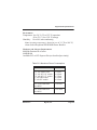
1
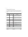
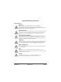
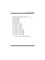
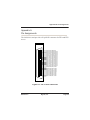
2400 Series AEX2400/TDM2400P User Manual Release 2.0 Digium, Inc. 445 Jan Davis Drive Huntsville, AL 35806 United States Main Number: 1.256.428.6000 Tech Support: 1.256.428.6161 U.S. Toll Free: 1.877.344.4861 Sales: 1.256.428.6262 www.digium.com www.asterisk.org www.asterisknow.org © Digium, Inc. 2007 All rights reserved. No part of this publication may be copied, distributed, transmitted, transcribed, stored in a retrieval system, or translated into any human or computer language without the prior written permission of Digium, Inc. Digium, Inc. has made every effort to ensure that the instructions contained in this document are adequate and error free. The manufacturer will, if necessary, explain issues which may not be covered by this documentation. The manufacturer’s liability for any errors in the documents is limited to the correction of errors and the aforementioned advisory services. This document has been prepared for use by professional and properly trained personnel, and the customer assumes full responsibility when using it. Adobe and Acrobat are registered trademarks, and Acrobat Reader is a trademark of Adobe Systems Incorporated. Asterisk and Digium are registered trademarks and Asterisk Business Edition, AsteriskNOW, AsteriskGUI, and Asterisk Appliance are trademarks of Digium, Inc. Any other trademarks mentioned in the document are the property of their respective owners. Release 2.0 Digium, Inc. Page 2 Safety Certification and Agency Approvals Safety: US/CSA 60950 IEC 60950 EN 60950 Other: CE Mark 2002/95/EC Restrictions on Hazardous Substances (RoHS), 2005/747/EC lead free exemption (Annex C) Telecom: FCC Part 68, ANSI/ITA-968-A, Including Amendment A1 and A2 PTC220 EMC: FCC Part 15 Class A EN55022/CISPR22 Class A EN55025 IEC 61000 Release 2.0 Digium, Inc. Page 3 Federal Communications Commission Part 68 This equipment complies with Part 68 of the FCC rules and the requirements adopted by the ACTA. On the back of the 2400 Series printed circuit board is a label that contains, among other information, a product identifier in the format US:AAAEQ##TXXXX. If requested, this number must be provided to the telephone company. A plug and jack used to connect this equipment to the premises wiring and telephone network must comply with the applicable FCC Part 68 rules and requirements adopted by the ACTA. The REN is used to determine the number of devices that may be connected to a telephone line. Excessive RENs on a telephone line may result in the devices not ringing in response to an incoming call. In most but not all areas, the sum of RENs should not exceed five (5.0). To be certain of the number of devices that may be connected to a line, as determined by the total RENs, contact the local telephone company. For products approved after July 23, 2001, the REN is part of the product identifier that has the format US:AAAEQ##TXXXX. The digits represented by ## are the REN without a decimal point (e.g., 03 is a REN of 0.3). If the 2400 Series causes harm to the telephone network, the telephone company may notify you in advance that temporary discontinuance of service may be required. But if advance notice is not practical, the telephone company will notify you as soon as possible. Also, you will be advised of your right to file a complaint with the FCC if you believe it is necessary. Release 2.0 Digium, Inc. Page 4 The telephone company may make changes in its facilities, equipment, operations or procedures that could affect the operation of the equipment. If this happens, the telephone company will provide advance notice in order for you to make necessary modifications to maintain uninterrupted service. Federal Communications Commission Part 15 This device complies with Part 15 of FCC rules. Operation is subject to the following two conditions: (1) This device may no cause harmful interference, and (2) This device must accept any interference received, including interference that may cause undesired operation. Industry Canada This Class A digital apparatus meets all requirements of the Canadian Interference-Causing Equipment Regulation. Cet appareil numerique de la class A respecte les exigences du Reglement sur le Material Brouilleur du Canada. Release 2.0 Digium, Inc. Page 5 Introduction to 2400 Series Documentation This manual contains product information for the 2400 Series card. Be sure to refer to any supplementary documents or release notes that were shipped with your equipment. The manual is organized in the following manner: Chapter/ Appendix Title Description 1 Overview Identifies the card and type of modules you received with your 2400 Series card. This chapter covers applications and uses of the 2400 Series card in the real world. 2 Card Installation Provides instructions for installing the card in your PC, acquiring correct drivers, and checking device compatibility. 3 Configuration Provides examples for configuring dial plan options. 4 FXS and FXO Explained Describes the FXO (Foreign Exchange Office) and FXS (Foreign Exchange Station) modules and their significance. 5 Troubleshooting Explains resolutions to common problems and frequently asked questions pertaining to card installation and usage. A Pin Assignments Lists the connectors and pin assignments. B Specifications Details card specifications. C Glossary and Acronyms A list of terms and acronyms used throughout this manual. Release 2.0 Digium, Inc. Page 6 Symbol Definitions Caution statements indicate a condition where damage to the unit or its configuration could occur if operational procedures are not followed. To reduce the risk of damage or injury, follow all steps or procedures as instructed. The ESD symbol indicates electrostatic sensitive devices. Observe precautions for handling devices. Wear a properly grounded electrostatic discharge (ESD) wrist strap while handling the device. The Electrical Hazard Symbol indicates a possibility of electrical shock when operating this unit in certain situations. To reduce the risk of damage or injury, follow all steps or procedures as instructed. Release 2.0 Digium, Inc. Page 7 Important Safety Instructions User Cautions Warning This card must be used with the PC lid screwed down. Telecommunications network voltages exist inside the PC! The PC must be shut down and telecommunications line connection shall be removed before opening the PC. Electrical Shock. To reduce the risk of injury, damage to the unit or your equipment, do not attempt to touch the modules while they are powered. The case should be securely closed before power is applied to the unit. Alarm Dialing Equipment. If your home has specially wired alarm equipment connected to the telephone line, ensure the installation of the 2400 Series does not disable your alarm equipment. If you have questions, consult your telephone company or a qualified installer. Servicing. Do not attempt to service this card unless specifically instructed to do so. Do not attempt to remove the card from your equipment while power is present. Refer servicing to qualified service personnel. Water and Moisture. Do not spill liquids on this unit. Do not operate this equipment in a wet environment. Heat. Do not operate or store this product near heat sources such as radiators, air ducts, areas subject to direct, intense sunlight, or other products that produce heat. Caution. To reduce the risk of fire, use only No. 26 AWG or larger telecommunication wiring for network connections. Release 2.0 Digium, Inc. Page 8 User Cautions Caution. This card is not intended for home use. It must be used in restricted access locations and installed in UL Listed I.T.E. only. Static Electricity. To reduce the risk of damaging the unit or your equipment, do not attempt to open the enclosure or gain access to areas where you are not instructed to do so. Refer servicing to qualified service personnel. Save these instructions for future reference. Service Personnel Cautions Warning. This card must be used with the PC lid screwed down. Telecommunications network voltages exist inside the PC! The PC must be shut down and telecommunications line connection shall be removed before opening the PC. Electrical Shock. To reduce the risk of injury, damage to the unit or your equipment, do not attempt to touch the modules while they are powered. The case should be securely closed before power is applied to the unit. Servicing. Disconnect telecommunications network cable before opening the cover or removing the card from the motherboard. Labeling. For safety reasons, only connect equipment with a Telecommunications Compliance label. This includes customer equipment previously labelled Permitted or Certified. Caution. Only connect regulatory equipment (approved for use in your specific country) to the telecommunications network voltage circuit ports. Release 2.0 Digium, Inc. Page 9 Service Personnel Cautions Caution. This card is not intended for home use. It must be used in restricted access locations and installed in UL Listed I.T.E. only. Release 2.0 Digium, Inc. Page 10 Table Of Contents TABLE OF CONTENTS Chapter 1 Overview . . . . . . . . . . . . . . . . . . . . . . . . . . . . . . . . . . . . . . . . . . . . . . . 17 Echo-Cancellation . . . . . . . . . . . . . . . . . . . . . . . . . . . . . . . . . . . . . . 20 What is Asterisk? . . . . . . . . . . . . . . . . . . . . . . . . . . . . . . . . . . . . . . .21 Chapter 2 Card Installation . . . . . . . . . . . . . . . . . . . . . . . . . . . . . . . . . . . . . . . . . 22 Unpacking the Card . . . . . . . . . . . . . . . . . . . . . . . . . . . . . . . . . . . . . 22 Shipment Inspection . . . . . . . . . . . . . . . . . . . . . . . . . . . . . . . . . . . . 23 Module Identification . . . . . . . . . . . . . . . . . . . . . . . . . . . . . . . . . . . . 23 FXS and FXS Connection . . . . . . . . . . . . . . . . . . . . . . . . . . . . . . . . 27 Slot Compatibility . . . . . . . . . . . . . . . . . . . . . . . . . . . . . . . . . . . . . . 28 Hardware Installation . . . . . . . . . . . . . . . . . . . . . . . . . . . . . . . . . . . 30 Software Installation . . . . . . . . . . . . . . . . . . . . . . . . . . . . . . . . . . . .33 Chapter 3 Configuration . . . . . . . . . . . . . . . . . . . . . . . . . . . . . . . . . . . . . . . . . . . . 40 General Options. . . . . . . . . . . . . . . . . . . . . . . . . . . . . . . . . . . . . . . .40 Voicemail . . . . . . . . . . . . . . . . . . . . . . . . . . . . . . . . . . . . . . . . . . . . 42 Testing Your Configuration . . . . . . . . . . . . . . . . . . . . . . . . . . . . . . . 44 Chapter 4 FXS and FXO Explained . . . . . . . . . . . . . . . . . . . . . . . . . . . . . . . . . . . 46 Identification. . . . . . . . . . . . . . . . . . . . . . . . . . . . . . . . . . . . . . . . . . . 46 FXS Module . . . . . . . . . . . . . . . . . . . . . . . . . . . . . . . . . . . . . . . . . .46 Release 2.0 Digium, Inc. Page 11 Table Of Contents FXO Module. . . . . . . . . . . . . . . . . . . . . . . . . . . . . . . . . . . . . . . . . . . 46 Using Your 2400 Series Card . . . . . . . . . . . . . . . . . . . . . . . . . . . . . 47 Chapter 5 Troubleshooting . . . . . . . . . . . . . . . . . . . . . . . . . . . . . . . . . . . . . . . . . 48 How do I identify which card I have using software? . . . . . . . . . . . . 49 The FXO module never seems to hang-up the line. How do I set it to hang-up? . . . . . . . . . . . . . . . . . . . . . . . . . . . . . . . . . . . . . . . . . . . . . 50 I have echo problems on my FXO modules. What can I do? . . . . . 50 Common Fixes. . . . . . . . . . . . . . . . . . . . . . . . . . . . . . . . . . . . . . . . . 51 There is a slight echo. How can I adjust the sound quality? . . . . . . 52 How can I enable more features? . . . . . . . . . . . . . . . . . . . . . . . . . . 52 Where can I find answers to additional questions? . . . . . . . . . . . . .52 Subscription Services Program . . . . . . . . . . . . . . . . . . . . . . . . . . . . 53 Appendix A Pin Assignments . . . . . . . . . . . . . . . . . . . . . . . . . . . . . . . . . . . . . . . . . 54 Appendix B Specifications . . . . . . . . . . . . . . . . . . . . . . . . . . . . . . . . . . . . . . . . . . . 55 Physical . . . . . . . . . . . . . . . . . . . . . . . . . . . . . . . . . . . . . . . . . . . . . . . . .55 Interfaces . . . . . . . . . . . . . . . . . . . . . . . . . . . . . . . . . . . . . . . . . . . . . . . . 55 Environment . . . . . . . . . . . . . . . . . . . . . . . . . . . . . . . . . . . . . . . . . . . . . .56 Hardware and Software Requirements . . . . . . . . . . . . . . . . . . . . . . . . . 56 Appendix C Glossary and Acronyms . . . . . . . . . . . . . . . . . . . . . . . . . . . . . . . . . . . 58 Page 12 Digium, Inc. Release 2.0 List of Figures Figure 1: Figure 2: Figure 3: Figure 4: Figure 5: Figure 6: Figure 7: Figure 8: Figure 9: Figure 10: Figure 11: Release 1.2 Sample Application - Channel Bank . . . . . . . . . . . . .17 Sample Application - Legacy PBX . . . . . . . . . . . . . . 18 Sample Application - Toll-bypass . . . . . . . . . . . . . . . 18 Sample Application - Analog to VoIP Transcoding . . 19 TDM2400P Card (Model TDM2433E) . . . . . . . . . . . 24 AEX2400 Card (Model TDM2433E) . . . . . . . . . . . . .25 Motherboard PCI Slots . . . . . . . . . . . . . . . . . . . . . . . 28 Insert the Card . . . . . . . . . . . . . . . . . . . . . . . . . . . . .30 Connect Power for FXS Quad Modules . . . . . . . . . .31 Example dmesg Screen Shot . . . . . . . . . . . . . . . . . . 39 Sample Application . . . . . . . . . . . . . . . . . . . . . . . . . .45 Digium, Inc. Page 15 List of Tables Table 1: Table 2: Table 3: Table B-1: Release 1.2 Example TDM2400P Card Configurations. . . . . . . . 26 Example AEX2400 Card Configurations . . . . . . . . . 27 Card Identifiers . . . . . . . . . . . . . . . . . . . . . . . . . . . . 34 Maximum Power Consumption . . . . . . . . . . . . . . . . .56 Digium, Inc. Page 16 Chapter 1: Overview Chapter 1 Overview The 2400 Series cards are versatile devices used for connecting your phone network to the PSTN (Public Switched Telephone Network) world. This is accomplished through phone lines connected to the FXO (Foreign Exchange Office) ports and phones connected via the FXS (Foreign Exchange Station) ports. The card allows Asterisk to connect to your phone network, creating an office type telephony environment. There are a variety of applications where the 2400 Series cards can prove useful. Some examples are provided in the following figures. Figure 1: Sample Application - Channel Bank Release 2.0 Digium, Inc. Page 17 Chapter 1: Overview Figure 2: Sample Application - Legacy PBX Figure 3: Sample Application - Toll-bypass Release 2.0 Digium, Inc. Page 18 Chapter 1: Overview Figure 4: Sample Application - Analog to VoIP Transcoding Release 2.0 Digium, Inc. Page 19 Chapter 1: Overview Echo-Cancellation Users connecting their 2400 Series cards to the PSTN or other devices are likely to be placing calls that will result, at some point, in an unbalanced 4-wire/2-wire hybrid. The result of this hybrid is the reflection of a nearend echo to the calling party. Elimination of this echo is the responsibility of echo cancellation. The 2400 Series cards, unless otherwise equipped, utilize Asterisk to perform software-based echo cancellation. Asterisk maintains a number of open source echo cancelers. These open source echo cancelers provide a moderate level of echo cancellation, but are not capable of dealing with higher levels of, or more advanced, echoes. Digium recommends that those users concerned about echo cancellation purchase the VPMADT032 hardware echo cancellation module. The VPMADT032 may be combined with both the TE2400P and AEX2400. The VPMADT032 is designed to handle up to 128ms of echo cancellation across all channels and provides a G.168 compliant and AT&T Labs certified Toll-Quality echo cancellation solution. Release 2.0 Digium, Inc. Page 20 Chapter 1: Overview What is Asterisk? Asterisk is the first open-source telephony platform. Since it runs on Linux, it inherits all of the power and stability of that operating system. The name Asterisk is derived from the all-inclusive “wildcard” symbol in UNIX. It is representative of the wide range of opportunities it opens for developers worldwide to create solutions which would otherwise be costprohibitive. Asterisk allows you to create a PBX solution that rivals the features and functionality of traditional telephony switches. Current PBX solutions are expensive and proprietary. International companies are discovering that Asterisk is cost effective, low maintenance, and flexible enough to handle all of their voice and data networking. Combined with Digium hardware and a common PC, anyone can replace an existing switch or complement a PBX by adding VoIP, voicemail, conferencing, and many other capabilities. Asterisk will integrate with most standards-based IP telephone handsets and software. Analog phones and ADSI-screen phones are also supported. Release 2.0 Digium, Inc. Page 21 Chapter 2: Card Installation Chapter 2 Card Installation This chapter provides the following information: Unpacking the Card on page 22 Shipment Inspection on page 23 Module Identification on page 23 FXS and FXS Connection on page 27 Hardware Installation on page 30 Software Installation on page 33 Unpacking the Card When you unpack your card, carefully inspect it for any damage that may have occurred in shipment. If damage is suspected, file a claim with the carrier and contact the reseller from which the card was purchased, or Digium Technical Support (+1.256.428.6161). Keep the original shipping container to use for future shipment or proof of damage during shipment. Note: Only qualified service personnel should install the card. Users should not attempt to perform this function themselves. The installer must ensure that the equipment is permanently connected equipment, pluggable type B or connected to a socket-outlet that has been checked to ensure that it is reliably earthed in accordance with the National Electrical Code. Release 2.0 Digium, Inc. Page 22 Chapter 2: Card Installation This card is intended for installation in a Restricted Access Location (RAL) only. Shipment Inspection The following items are included in shipment of the 2400 Series card: 2400 Series card (TDM2400P or AEX2400) A combination of FXO and/or FXS quad modules (depending on configuration) Module Identification The 2400 Series card ships with FXO and/or FXS quad modules in place. These are identified by their color. Take a moment to identify which quad modules were shipped with your card. FXO (Foreign Exchange Office) quad modules are Red FXS (Foreign Exchange Station) quad modules are Green See Figure 5 on page 24 for an example of the card shown with three of each quad module. Note: It is important to identify the type and location of your 2400 Series quad modules. You will need this information during the Asterisk configuration. There are multiple configurations in which the 2400 Series card may be purchased. Each configuration consists of one to six FXS and/or FXO quad modules. See Table 1 on page 26 for a complete list of possible configurations. Release 2.0 Digium, Inc. Page 23 Chapter 2: Card Installation The 2400 Series cards may also be combined with Digium’s hardwarebased echo canceler, model VPMADT032. See Figure 6 on page 25 for an example of the AEX2400 card shown with one of each quad analog module and the echo cancellation module. FXO Quad Modules (Red) FXS Quad Modules (Green) Female RJ-21X 1 2 3 Echo Cancellation Module 4 5 6 Power Supply Connection Figure 5: TDM2400P Card (Model TDM2433E) Release 2.0 Digium, Inc. Page 24 Chapter 2: Card Installation FXO Quad Modules FXS Quad Modules Female RJ-21X 1 2 3 Echo Cancellation Module 4 5 6 Power Supply Connection Figure 6: AEX2400 Card (Model TDM2433E) Release 2.0 Digium, Inc. Page 25 Chapter 2: Card Installation Card Identification There are multiple configurations in which a 2400 Series card may be purchased. Each configuration consists of a combination of quad modules and may also include the VPMADT032 echo cancellation module. See Table 1 on page 26 for a list of the most common TDM2400P configurations. See Table 2 on page 27 for a list of the most common AEX2400 configurations. The lists are not complete, but rather an example of the configurations available. It is easiest to identify your card by understanding the naming scheme for each card. The first two digits are the maximum port count of the card. The third digit is the number of FXS (station) ports present on the card. The fourth digit provides the number of FXO (station) ports present on the card. Table 1: Example TDM2400P Card Configurations FXO/FXS Ports Card ID TDM2401B 1 quad FXO module TDM2406B 6 quad FXO modules TDM2433B 3 quad FXO modules and 3 quad FXS modules TDM2451B 5 quad FXS and 1 quad FXO modules TDM2460B 6 FXS modules Release 2.0 Digium, Inc. Page 26 Chapter 2: Card Installation Table 2: Example AEX2400 Card Configurations FXO/FXS Ports Card ID AEX2401B 1 quad FXO module AEX2406B 6 quad FXO modules AEX2433B 3 quad FXO modules and 3 quad FXS modules AEX2451B 5 quad FXS and 1 quad FXO modules AEX2460B 6 FXS modules FXS and FXS Connection The 2400 Series card provides a 50-pin RJ-21X connector for access to the FXS and/or FXO quad modules installed in the six available slots. The diagram in Figure A-1 on page 54 provides the pinout for this connector. Caution. Only qualified service personnel should continue with hardware installation and configuration of the 2400 Series card. Users should not attempt to perform these functions themselves. Release 2.0 Digium, Inc. Page 27 Chapter 2: Card Installation Slot Compatibility Check the type of card you received to be sure it is compatible with your PCI slot. To determine which slot you have, identify it by comparing it to those shown in Figure 7 on page 28. Slot Number: 0: AGP Pro Slot 1: 64-bit 5.0 volt PCI Slot 2: 64-bit 3.3 volt PCI Slot 3: 32-bit 5.0 volt PCI Slot 4: PCI Express Slot Slots 0 1 2 3 4 Figure 7: Motherboard PCI Slots Release 2.0 Digium, Inc. Page 28 Chapter 2: Card Installation The TDM2400P card is a 32-bit 33MHz card keyed for universal 3.3 volt or 5.0 volt operation and works in any PCI 2.2 (or greater) compliant slot. This means that in the motherboard shown in Figure 7, the TDM2400 card will fit into Slots 1, 2, or 3 (PCI slots) but will not fit into Slot 0 (AGP slot), or Slot 4 (PCI Express slot). The AEX2400 card is a PCI Express card. Slot 4, illustrated above, is a 1 lane (X1) PCI Express compliant slot. The AEX2400 will work in any PCI Express compliant slot, including lane lengths X4, X8, and X16. This means that in the motherboard shown in Figure , the AEX2400 will only fit into Slot 4. The AEX2400 can not be used in Slots 0 through 3. Release 2.0 Digium, Inc. Page 29 Chapter 2: Card Installation Hardware Installation 1. Now that you are acquainted with your card, power down your computer and unplug it from its power source. 2. Attach a static strap to your wrist and open the case. 3. Remove the bracket place holder and insert the card into a PCI (TDM2400P) or PCI Express (AEX2400) slot. See Figure 8. Figure 8: Insert the Card 4. If your card has any FXS quad modules, you will also need to connect the power cable from your computer’s power supply to the bottom of the card. Insert a four-pin 12 volt connector (disk drive power supply cable, e.g. hard drive) into the white plastic connector on the bottom of the card. See Figure 9. Release 2.0 Digium, Inc. Page 30 Chapter 2: Card Installation Figure 9: Connect Power for FXS Quad Modules Some computers do not have power cables available within the chassis. If you have FXS modules on your 2400 Series card and your computer does not have power cables available, then power must be provided to the 2400 Series card by an alternate means. Digium provides a solution to this problem with the PWR2400B. This card is essentially a PCI bracket assembly that takes power from an external DC power supply and routes it to two 15" power cables inside the computer. You must have an available bracket slot to use the PWR2400B (either PCI, PCI Express or AGP). A strap on the PWR2400B card allows the two power cables to take power from the same DC supply. The PWR2400B comes with one power supply capable of supporting up to 24 FXS ports each, driving heavy loads of up to 5REN. If more than 24 FXS ports with heavy loads are connected to the PWR2400B then a second Digium power Supply should be purchased. The shorting strap on the PWR2400B should be removed if a second power supply is used. Release 2.0 Digium, Inc. Page 31 Chapter 2: Card Installation The PWR2400B does not connect to any bus inside the computer. It may be used wherever there is an available PCI-size bracket such as a PCI, PCI Express, or AGP slot. Note: The PWR2400B is not intended to supply power to any other device, it is intended only to be used with UL Listed Digium cards. 5. Replace the cover to your computer. Electrical Shock. To reduce the risk of injury, damage to the unit or your equipment, do not attempt to apply power to the unit while the case is open.Personal injury or damage to the unit could occur if the modules are touched while powered is applied. 6. Plug all outside phone lines to the FXO (red) ports and connect all phones to the FXS (green) ports as needed using a patch panel or punch block. See Figure A-1 on page 54 for the RJ-21X pin assignments. Caution. This unit must be connected to the Telecommunications Network in your country using an approved line cord, e.g.: for Australia use only line cords complying with ACA Technical Standard TS008. Caution. Only connect regulatory equipment (approved for use in your specific country) to the telecommunications network voltage circuit ports. Release 2.0 Digium, Inc. Page 32 Chapter 2: Card Installation Software Installation Digium hardware requires drivers and libraries that are not integrated with the Linux kernel. The 2400 Series cards are only supported under Linux. Digium, Inc. recommends Debian, Fedora, and Red Hat. However, many other distributions are supported by Digium Technical Support. You can obtain the source code from downloads.digium.com. Detailed instructions are provided in this section. Note: Please refer to asterisk.org for an introduction to Asterisk, its configuration and features, and set up and use of Zaptel channels. To install your 2400 Series card, you will need: Full Linux kernel 2.6 (or later) source code. Development libraries and headers for libncurses (Asterisk 1.2 or Asterisk/Zaptel 1.4). Development libraries and headers for zlib and openssl. GCC and standard build tools. Development libraries and headers for libnewt (only necessary for Zaptel). If you are using the 1.2.x series of Asterisk and Zaptel, you will need Asterisk 1.2.24 or newer, and Zaptel 1.2.24 or newer. If you are using the 1.4.x series of Asterisk and Zaptel, you will need Asterisk 1.4.15or newer and Zaptel 1.4.15 or newer. Note: It is recommended that you use the most recent version of the Asterisk and Zaptel distributions for the best results. Note: If you already have both Asterisk and Zaptel installed, you will need to upgrade to the latest version of both. Release 2.0 Digium, Inc. Page 33 Chapter 2: Card Installation 1. Check your lspci PCI device listing. Boot the computer into Linux. After the machine has loaded, log in and execute the following: # lspci -n | grep d161 Confirm your lspci PCI device listing by scanning for the following information in the output screen: 0000:01:00.0 0200:d161:<card identifier> In the device listing shown above, <card identifier> will be populated with one of the identifiers listed in the table below. Table 3: Card Identifiers Model TDM2400P AEX2400 Identifier 2400 8003 An ISDN Controller for either the TDM2400P or the AEX2400 should be identified. If a controller is not identified, then your machine is not PCI 2.2 (or higher) or PCI Express compatible and the card will not work with your equipment. Release 2.0 Digium, Inc. Page 34 Chapter 2: Card Installation 2. Download the latest Zaptel drivers (1.2.24 or later) to your /usr/src directory. The Zaptel drivers are accessible via http from http:// downloads.digium.com/pub/telephony/zaptel/. 3. Expand the downloaded tarball and install the drivers. Substitute the version of Zaptel you are using with the X.X in the command lines below. #tar -zxvf zaptel-1.X.X.tar.gz #cd zaptel-1.X.X #make clean #./configure (applies to 1.4.X only) #make menuselect (applies to 1.4.X only if you wish to customize the install) #make #make install Note: If you don’t already have configuration files installed, you can type make samples to install the default sample configuration files. This action will overwrite any existing sample files. Release 2.0 Digium, Inc. Page 35 Chapter 2: Card Installation 4. Download the latest released version of Asterisk, either 1.2.24 (or later) or 1.4.15 (or later). Asterisk can be downloaded from http:// downloads.digium.com/pub/telephony/asterisk. 5. Expand the downloaded tarballs. Substitute the version of Asterisk you are using with the X.X in the command lines below. # tar -zxvf asterisk-1.X.X.tar.gz # cd asterisk-1.X.X/ # make clean #./configure (applies to 1.4.X only) # make menuselect (applies to 1.4.X only if you wish to customize the install) # make # make install Your installation of Zaptel and Asterisk should now be complete. If the build fails, it may be because you are missing one of the build dependencies, the kernel source, or development tools. Feel free to contact your reseller where the card was purchased, or e-mail Digium Technical Support via [email protected] for assistance. Additional instructions for installing Asterisk are available at www.asterisk.org. Release 2.0 Digium, Inc. Page 36 Chapter 2: Card Installation Zaptel Configuration The Zaptel Configuration file, /etc/zaptel.conf, needs to be edited in order for your 2400 Series card to work properly. The following steps are necessary for Zaptel configuration: 1. Open the zaptel.conf file from the etc directory. 2. If your card has any red FXO quad modules, add the following to zaptel.conf: fxsks This uses kewl start signalling which is loop start with disconnect supervision. For example, a TDM2406E card would be configured as the following: fxsks=1,2,3,4,5,6,7,8,9,10,11,12,13,14,15,16,17,18,19, 20,21,22,23,24 Note: You should have identified the type of 2400 Series card when you received it. If you are not sure, refer to Module Identification on page 19 for assistance. Note: The TDM2400P does not support Ground Start signaling. Release 2.0 Digium, Inc. Page 37 Chapter 2: Card Installation 3. If your card has any green FXS quad modules, add the following: fxoks This uses kewl start signalling which is loop start with disconnect supervision. For example, a TDM2406E card would be configured as the following: fxoks=1,2,3,4,5,6,7,8,9,10,11,12,13,14,15,16,17,18,19, 20,21,22,23,24 An example TDM2433E card configuration would be: fxoks=1,2,3,4,5,6,7,8,9,10,11,12 fxsks=13,14,15,16,17,18,19,20,21,22,23,24 4. Set your loadzone and default zone for your country. If you are not in the United States, you will want to change the default configuration from US to your own two letter country abbreviation. Save the file and return to the command line. #modprobe wctdm24xxp #ztcfg -vv 5. Confirm the card configuration by initiating a dmesg command. The example in Figure 10 on page 39 shows a sample of the dmesg screen output for a TDM2433B card. The text shown may vary slightly depending on the type of card installed. Release 2.0 Digium, Inc. Page 38 Chapter 2: Card Installation Figure 10: Example dmesg Screen Shot Release 2.0 Digium, Inc. Page 39 Chapter 3: Configuration Chapter 3 Configuration This chapter provides sample configurations to demonstrate customizing the Asterisk software to meet your individual needs. Each section explains basic options as examples. Once you have familiarized yourself with the samples, you can edit the configuration files to meet your specific needs. Note: Only qualified service personnel should install the card. Users should not attempt to perform this function themselves. General Options Open the zapata.conf file from the /etc directory. The following is a sample configuration for a TDM2422B card. You can place this at the bottom of your zapata.conf file. ;;General options usecallerid=yes hidecallerid=no callwaiting=yes threewaycalling=yes transfer=yes echocancel=yes echocancelwhenbridged=yes rxgain=0.0 txgain=0.0 ;;FXS Modules Release 2.0 Digium, Inc. Page 40 Chapter 3: Configuration Group=1 signalling=fxo_ks context=Internal channel=1-2 ;;FXO Modules Group=2 echocancel=yes signalling=fxs_ks context=Incoming channel=3-4 Users of Digium's hardware echo cancellation module, the VPMADT032, should set the echocancel option to "yes." The module will automatically configure itself to run at full capacity, 1024 taps (128ms), on each channel. Users without the VPMADT032 using open source echo cancelers included with Zaptel should configure echocancel to the values 128 (16ms) or 256 (32ms). Setting "yes" will default the option to 128 (16ms). Users who have not purchased the 2400 Series card with the hardware echo cancellation module are encouraged to take advantage of Digium's High Performance Echo Canceler software. This commercially licensed software, which is made available at no charge to in-warranty Digium analog interface card customers, provide toll quality echo cancellation, performed on the host CPU, at up to 1024 taps (128ms) per channel. For further details about HPEC, please refer to the Digium website here: http://www.digium.com/en/products/software/hpec.php Release 2.0 Digium, Inc. Page 41 Chapter 3: Configuration When HPEC is enabled, users may set the value of the echocancel parameter to any of the following values: 128 - 16ms 256 - 32ms 512 - 64ms 1024 - 128ms Note: Higher values will result in dramatically increased CPU consumption. In order to optimize system performance, users are encouraged to choose the minimum value required to cancel their echo. Voicemail Open voicemail.conf and find the following line at the bottom: [default] 1234 => 4242, Mark Spencer, root@localhost In this example, 1234 is the mailbox number, 4242 is the password, Mark Spencer is the person’s name, and root@localhost is his email address. You can add extensions by adding the following: 1000 => 1234, Moose Member, [email protected] 2000 => 1234, Bill Savage, [email protected] Release 2.0 Digium, Inc. Page 42 Chapter 3: Configuration Dial Plan Open extensions.conf, which contains a large, complex sample dial plan. In this step, you will configure a basic dial plan to enable you to send and receive calls. Go to the bottom of the file and add the following lines: [Internal] exten => 1000,1,Dial(zap/1,20,rt) exten => 1000,2,Voicemail(u1000) exten => 1000,102,Voicemail(b1000) exten => 2000,1,Dial(zap/2,20,rt) exten => 2000,2,Voicemail(u2000) exten => 2000,102,Voicemail(b2000) exten => 8500,1,VoiceMailMain exten => 8501,1,MusicOnHold exten => _9.,1,Dial(zap/g2/www${EXTEN:1}) exten => _9.,2,Congestion [Incoming] exten => s,1,Answer exten => s,2,Dial(zap/g1,20,rt) exten => s,3,Voicemail(u1000) exten => s,103,Voicemail(b1000) Release 2.0 Digium, Inc. Page 43 Chapter 3: Configuration In this example there are two internal extensions (1000 and 2000), a number to check voicemail (8500), a number to listen to musiconhold, (8501), and a prefix to dial to get an outside line (9). It is configured for incoming calls over the FXO rings phones 1 and 2, and voicemail is routed to mailbox 1000. Testing Your Configuration 1. Start Asterisk by typing: asterisk 2. Connect to Asterisk and view the output by typing: asterisk -vvvvr 3. Dial tone should be present on phones connected to the FXS ports. Test your configuration by placing an outgoing call, placing a call from extension 1 to 2, or receiving an incoming call. Successful completion of these tasks indicates your configuration is working properly. Release 2.0 Digium, Inc. Page 44 Chapter 3: Configuration Figure 11: Sample Application Note: More detailed information is provided on troubleshooting at the Asterisk website (www.asterisk.org) as well as the Digium Knowledge Base (kb.digium.com). You may also obtain assistance by contacting Digium Technical Support (+1.256.428.6161) or visiting the website at www.digium.com. Release 2.0 Digium, Inc. Page 45 Chapter 4: FXS and FXO Explained Chapter 4 FXS and FXO Explained Identification There are multiple standard configurations in which the 2400 Series card may be purchased. Each configuration consists of one to six FXS and/or FXO modules. These modules are identified by their color. FXS -Foreign Exchange Station (Green Modules) FXO -Foreign Exchange Office (Red Modules) This chapter provides an in-depth review of the two module types and their uses within your Asterisk server. Note: Only qualified service personnel should install the card. Users should not attempt to perform this function themselves. FXS Module The FXS module allows the 2400 Series card to initiate and send ringing voltage to an FXO device such as an analog telephone. FXO Module The FXO module allows the 2400 Series card to terminate analog telephone lines (POTS). Release 2.0 Digium, Inc. Page 46 Chapter 4: FXS and FXO Explained Because of the modular design, you can activate additional ports at any time with more FXS or FXO daughter cards. The FXO module passes all the call features any standard analog telephone line will support. The phone receiving the call is the last FXO device in the chain. When it receives voltage from an FXS device, the phone rings. Using Your 2400 Series Card Connect the outside line to an FXO port on your Asterisk server to receive voltage from the outside lines. Connect the phones to FXS ports on your Asterisk server. When the FXO module in your Asterisk Server receives the voltage, it will then generate voltage using the FXS module and send it to your analog phone. Release 2.0 Digium, Inc. Page 47 Chapter 5: Troubleshooting Chapter 5 Troubleshooting This chapter provides frequently asked questions as identified from Digium Technical Support and possible resolutions. Multiple resources are available to obtain more information about Asterisk and Digium products. Please visit both www.digium.com and www.asterisk.org for more information. Release 2.0 Digium, Inc. Page 48 Chapter 5: Troubleshooting How do I identify which card I have using software? Check your lspci PCI device listing. Boot the computer into Linux. After the machine has loaded, log in and execute the following: # lspci -n Confirm your lspci PCI device listing by scanning for the following information in the output screen: 0000:01:0e.0 ISDN controller: Unknown device d161:<card identifier> In the device listing shown above, <card identifier> will be populated with one of the identifiers listed in the table below.Card Identifiers Model TDM2400P AEX2400 Identifier 2400 8003 An ISDN Controller for either the TDM2400P or the AEX2400 should be identified. If a controller is not identified, then your machine is not PCI 2.2 (or higher) or PCI Express compatible and the card will not work with your equipment. Release 2.0 Digium, Inc. Page 49 Chapter 5: Troubleshooting The FXO module never seems to hang-up the line. How do I set it to hang-up? Set busydetect=yes and busycount=10 in the zapata.conf for your channels. This will cause the line to hang-up by listening for the busy tone. Upon editing zapata.conf, you will need to restart Asterisk. I have echo problems on my FXO modules and I've tried the different echo cancellation algorithms in zconfig.h, tried tweaking the gains, and still nothing works. What can I do? Use the fxotune utility. To use: Just run the fxotune utility with the -i option (fxotune -i 4). It should discover which zap channels are FXO modules and tune them accordingly. Be warned however, it takes a significant amount of time for EACH module to test, I would say somewhere around 2-3 minutes. But you only have to initialize it once for the line. It will write a configuration file to /etc/fxotune.conf. You will need to have your system run fxotune with the -s flag (fxotune -s) to set the module with the previously discovered values from fxotune.conf for it to take affect, so essentially if each time you reboot the machine you need to run fxotune -s. You might consider putting it in your startup scripts some time after the module loads and before asterisk runs. Note: The digit after the -i option is the digit that will break dialtone on the line. Release 2.0 Digium, Inc. Page 50 Chapter 5: Troubleshooting Common Fixes 1. Check to see if X windows is running by entering the following: ps aux|grep X If X windows is running, stop the application since it may cause a conflict with Asterisk. 2. Check to see if your IDE hard drives are running with DMA levels set. Advance user can perform an hdparm on your hard drive interface. Use hdparm with caution as the man page states that hard drive corruption can occur when using incorrect settings. Please review the man page for hdparm and make sure you understand the risks before using this tool. Check the current mode using this command: hdparm -vi /dev/[IDE Device] Use this command to set the drives into UDMA2 mode: hdparm -d 1 -X udma2 -c 3 /dev/[IDE Device] If you are still having problems, contact your reseller from which the card was purchased, or Digium Technical Support (+1.256.428.6161). Release 2.0 Digium, Inc. Page 51 Chapter 5: Troubleshooting There is a slight echo. How can I adjust the sound quality? There are several options available to correct this. Each involves editing the zapata.conf file. Be sure to restart Asterisk upon completion. 1. Adjust echocancel=yes to one of the following values: 32, 64, 128, or 256. 2. You can also set echotraining=yes. 3. You can also adjust the rxgain and the txgain, although it is only recommended to shift between -5 and 5. How can I enable more features? To view all of the options available to add to your dial plan, type the following command from within Asterisk: show applications Where can I find answers to additional questions? There are several places to inquire for more information about Asterisk Digium products: 1. Digium Technical Support (+1.256.428.6161), or Toll Free in the U.S. (1.877.344.4861), is available 7am-7pm Central Time (GMT -6), Monday - Friday. 2. Asterisk users mailing list (asterisk.org/lists.digium.com). 3. IRC channel #asterisk on (irc.freenode.net). Release 2.0 Digium, Inc. Page 52 Chapter 5: Troubleshooting Subscription Services Program Digium is dedicated to supporting your Asterisk system by offering full technical support through our Subscription Services Program. Through this program, you can be at ease knowing that your business will always have access to the Asterisk experts. Pricing on Subscription Services may be obtained from your nearest reseller or you may call Digium Sales for referral to your nearest reseller at +1.256.428.6000 or e-mail [email protected]. Release 2.0 Digium, Inc. Page 53 Appendix A: Pin Assignments Appendix A Pin Assignments The 2400 Series card provides a 50-pin RJ21 connector for FXO and FXS access. 50 25 Pins 25 & 50, Not Used Pins 24 & 49, Port 24, Slot 6 Pins 23 & 48, Port 23, Slot 6 Pins 22 & 47, Port 22, Slot 6 Pins 21 & 46, Port 21, Slot 6 Pins 20 & 45, Port 20, Slot 5 Pins 19 & 44, Port 19, Slot 5 Pins 18 & 43, Port 18, Slot 5 Pins 17 & 42, Port 17, Slot 5 Pins 16 & 41, Port 16, Slot 4 Pins 15 & 40, Port 15, Slot 4 Pins 14 & 39, Port 14, Slot 4 Pins 13 & 38, Port 13, Slot 4 Pins 12 & 37, Port 12, Slot 3 Pins 11 & 36, Port 11, Slot 3 Pins 10 & 35, Port 10, Slot 3 Pins 9 & 34, Port 9, Slot 3 Pins 8 & 33, Port 8, Slot 2 Pins 7 & 32, Port 7, Slot 2 Pins 6 & 31, Port 6, Slot 2 Pins 5 & 30, Port 5, Slot 2 Pins 4 & 29, Port 4, Slot 1 Pins 3 & 28, Port 3, Slot 1 Pins 2 & 27, Port 2, Slot 1 Pins 1 & 26, Port 1, Slot 1 26 1 Figure A-1: RJ-21 Port Connector Release 2.0 Digium, Inc. Page 54 Appendix B: Specifications Appendix B Specifications This appendix provides specifications, required environmental conditions, and maximum power consumption for the 2400 Series cards. Physical. Size: Weight: 12.28” × 4.2” × 0.68” (31.19 x 10.67 x 1.72 cm) PCB size, does not include the PCI bracket or retainer. 5.8 oz (164.43gm) with no modules loaded. Each quad module adds 1 oz (28.3gm) Interfaces. Local Loop Access: Industry standard 50-pin RJ-21 (amphenol). Note: RJ-21 cables and patch panels are available from Digium. PCI Bus (TDM2400P): 3.3V or 5V bus slot, full length full height, 33MHz minimum bus speed, compliant with PCI 2.2 or greater. (AEX2400) - PCI-E X1, compliant with PCI-E X1 1.0 or greater. Additional Power: Four-pin 12V connector for FXS power supply (required only if FXS modules are installed) Release 2.0 Digium, Inc. Page 55 Appendix B: Specifications Environment. Temperature: 0 to 50° C (32 to 122° F) operation -20 to 70° C (4 to 158° F) storage Humidity: 10 to 90% non-condensing Note: Operating temperature is limited to 0 to 40° C (32 to 104° F) when used with optional PWR2400B Power Bracket. Hardware and Software Requirements. 800-Mhz Pentium III or better 64MB RAM Available PCI or PCI-Express Slot (as described previously) Table B-1: Maximum Power Consumption Model Release 2.0 Power 3.3V All TDM models 3.3V All AEX “B” models 3.3V All AEX “E” models 5V All TDM models 5V All AEX models 1.0 Watt 4.0 Watts 4.7 Watts 9.0 Watts 0.0 Watts 12V AEX/TDM2406E into 1REN 11.0 Watt 12V AEX/TDM2433E into 2REN 12.0 Watts Digium, Inc. Page 56 Appendix B: Specifications Table B-1: Maximum Power Consumption Model Release 2.0 Power 12V AEX/TDM2433E into 3REN 15.0 Watts 12V AEX/TDM2433E into 4REN 17.5 Watts 12V AEX/TDM2433E into 5REN 20.0 Watts Digium, Inc. Page 57 Appendix C: Glossary and Acronyms Appendix C Glossary and Acronyms ANSI American National Standards Institute An organization which proposes and establishes standards for international communications. asynchronous Not synchronized; not timed to an outside clock source. Transmission is controlled by start bits at the beginning and stop bits at the end of each character. Asynchronous communications are often found in internet access and remote office applications. attenuation The dissipation of a transmitted signal’s power as it travels over a wire. bandwidth The capacity to carry traffic. Higher bandwidth indicates the ability to transfer more data in a given time period. bit The smallest element of information in a digital system. A bit can be either a zero or a one. bps bits per second A measurement of transmission speed across a data connection. Release 2.0 Digium, Inc. Page 58 Appendix C: Glossary and Acronyms broadband Broadband transmission shares the bandwidth of a particular medium (copper or fiber optic) to integrate multiple signals. The channels take up different frequencies on the cable, integrating voice, data, and video over one line. channel A generic term for an individual data stream. Service providers can use multiplexing techniques to transmit multiple channels over a common medium. Cat5 Category of Performance for wiring and cabling. Cat 5 cabling support applications up to 100 MHz. Cat5E Category of Performance for wiring and cabling. Category 5 Enhanced wiring supports signal rates up to 100 MHz but adheres to stricter quality specifications. CLEC competitive local exchange carrier A term for telephone companies established after the Telecommunications Act of 1996 deregulated the LECs. CLECs compete with ILECs to offer local service. See also LEC and ILEC. Release 2.0 Digium, Inc. Page 59 Appendix C: Glossary and Acronyms CO central office The CO houses local switching equipment. All local access lines in a particular geographic area terminate at this facility (which is usually owned and operated by an ILEC). CPE customer premises equipment Terminal equipment which is connected to the telecommunications network and which resides within the home or office of the customer. This includes telephones, modems, terminals, routers, and television set-top boxes. DS0 Digital Signal, Level 0 A voice grade channel of 64 Kbps. The worldwide standard speed for digitizing voice conversation using PCM (Pulse Code Modulation). DS1 Digital Signal, Level 1 1.544 Mbps in North America (T1) and Japan (J1) -up to 24 voice channels (DS0s), 2.048 Mbps in Europe (E1) - up to 32 voice channels (DS0s). DS1/T1/E1 lines are part of the PSTN. DS3 Digital Signal, Level 3 T3 in North America and Japan, E3 in Europe. Up to 672 voice channels (DS0s). DS3/T3/E3 lines are not part of the PSTN DTMF Dual Tone Multi-Frequency Push-button or touch tone dialing. Release 2.0 Digium, Inc. Page 60 Appendix C: Glossary and Acronyms E1 The European equivalent of North American T1, transmits data at 2.048 Mbps, up to 32 voice channels (DS0s). E3 The European equivalent of North American T3, transmits data at 34.368 Mbps, up to 512 voice channels (DS0s). Equivalent to 16 E1 lines. EMI Electromagnetic Interference Unwanted electrical noise present on a power line full duplex Data transmission in two directions simultaneously. FXO Foreign Exchange Office Receives the ringing voltage from an FXS device. Outside lines are connected to the FXO port on your 2400 Series card. FXS Foreign Exchange Station Initiates and sends ringing voltage. Phones are connected to the FXS ports on the 2400 Series card. G.711 The International Telecommunications Union recommendation for an algorithm designed to transmit and receive maelaw PCM voice and A-law at digital bit rate 64 Kbps. This algorithm is used for digital telephone sets on digital PBX. Release 2.0 Digium, Inc. Page 61 Appendix C: Glossary and Acronyms G.729 The International Telecommunications Union standard for voice algorithm. H.323 The International Telecommunications Union standard for multimedia communications over packet-based networks. IAX Inter-Asterisk eXchange The protocol used by Asterisk. It is used to enable VoIP connections between Asterisk servers, and between servers and clients that also use the IAX protocol. iLBC internet Low Bitrate Codec A free speech codec used for voice over IP. It is designed for narrow band speech with a payload bitrate of 13.33 kbps (frame length = 30ms) and 15.2 kbps (frame length = 20 ms). ILEC incumbent local exchange carrier The LECs that were the original carriers in the market prior to the entry of competition and therefore have the dominant position in the market. interface A point of contact between two systems, networks, or devices. Release 2.0 Digium, Inc. Page 62 Appendix C: Glossary and Acronyms ISO International Standards Organization LED light-emitting diode Linux A robust, feature-packed open source operating system based on Unix that remains freely available on the internet. It boasts dependability and offers a wide range of compatibility with hardware and software. Asterisk runs exclusively on Linux. loopback A state in which the transmit signal is reversed back as the receive signal, typically by a far-end network element. MGCP Media Gateway Control Protocol multiplexing Transmitting multiple signals over a single line or channel. FDM (frequency division multiplexing) and TDM (time division multiplexing) are the two most common methods. FDM separates signals by dividing the data onto different carrier frequencies, and TDM separates signals by interleaving bits one after the other. MUX multiplexer A device which transmits multiple signals over a single communications line or channel. See multiplexing. Release 2.0 Digium, Inc. Page 63 Appendix C: Glossary and Acronyms PBX private branch exchange A smaller version of a phone company’s large central switching office. Example: Asterisk. PCI peripheral component interconnect A standard bus used in most computers to connect peripheral devices. POP point of presence The physical connection point between a network and a telephone network. A POP is usually a network node serving as the equivalent of a CO to a network service provider or an interexchange carrier. POTS plain old telephone service Standard phone service over the public switched telephone network (PSTN). This service provides analog bandwidth of less than 4 kHz. PPP point-to-point protocol Type of communications link that connects a single device to another single device, such as a remote terminal to a host computer. PSTN public switched telephone network A communications network which uses telephones to establish connections between two points. Also referred to as the dial network. QoS quality of service A measure of telephone service, as specified by the Public Service Commission. Release 2.0 Digium, Inc. Page 64 Appendix C: Glossary and Acronyms RJ11 A six pin jack typically used for connecting telephones, modems, and fax machines in residential and business settings to PBX or the local telephone CO. SIP Session Initiation Protocol An IETF proposed standard for setting up sessions between one or more clients. It is currently the leading signaling protocol for Voice over IP, gradually replacing H.323. T1 A dedicated digital carrier facility which transmits up to 24 voice channels (DS0s) and transmits data at 1.544 Mbps. Commonly used to carry traffic to and from private business networks and ISPs. T3 A dedicated digital carrier facility which consists of 28 T1 lines and transmits data at 44.736 Mbps. Equivalent to 672 voice channels (DS0s). TDM time division multiplexer A device that supports simultaneous transmission of multiple data streams into a single high-speed data stream. TDM separates signals by interleaving bits one after the other. telco A generic name which refers to the telephone companies throughout the world, including RBOCs, LECs, and PTTs. Release 2.0 Digium, Inc. Page 65 Appendix C: Glossary and Acronyms tip and ring The standard termination on the two conductors of a telephone circuit; named after the physical appearance of the contact areas on the jack plug. twisted pair Two copper wires commonly used for telephony and data communications. The wires are wrapped loosely around each other to minimize radio frequency interference or interference from other pairs in the same bundle. V volts VoIP Voice over IP Technology used for transmitting voice traffic over a data network using the Internet Protocol. Zap Digium hardware interface. Release 2.0 Digium, Inc. Page 66