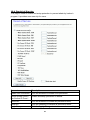
1
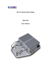
802.11g Wireless LAN Outdoor CPE AP/Router
WAP-6200
User’s Manual
Version 2.0
Copyright
Copyright© 2009 by PLANET Technology Corp.
All rights reserved. No part of this publication may be
reproduced, transmitted, transcribed, stored in a retrieval system, or translated into any language or computer
language, in any form or by any means, electronic, mechanical, magnetic, optical, chemical, manual or
otherwise, without the prior written permission of PLANET.
PLANET makes no representations or warranties, either expressed or implied, with respect to the contents
hereof and specifically disclaims any warranties, merchantability or fitness for any particular purpose.
Any
software described in this manual is sold or licensed "as is". Should the programs prove defective following
their purchase, the buyer (and not this company, its distributor, or its dealer) assumes the entire cost of all
necessary servicing, repair, and any incidental or consequential damages resulting from any defect in the
software. Further, this company reserves the right to revise this publication and to make changes from time to
time in the contents hereof without obligation to notify any person of such revision or changes..
All brand and product names mentioned in this manual are trademarks and/or registered trademarks of their
respective holders.
FCC Caution:
To assure continued compliance. (Example-use only shielded interface cables when connecting to computer or
peripheral devices). Any changes or modifications not expressly approved by the party responsible for
compliance could void the user’s authority to operate the equipment.
This device complies with Part 15 of the FCC Rules. Operation is subject to the Following two conditions: (1)
This device may not cause harmful interference, and (2) this Device must accept any interference received,
including interference that may cause undesired operation.
Federal Communication Commission (FCC) Radiation Exposure Statement
This equipment complies with FCC radiation exposure set forth for an uncontrolled environment. In order to
avoid the possibility of exceeding the FCC radio frequency exposure limits, human proximity to the antenna
shall not be less than 20 cm (8 inches) during normal operation.
CE Mark Warning
This is a Class B product. In a domestic environment, this product may cause radio interference, in which case
the user may be required to take adequate measures.
Protection requirements for health and safety – Article 3.1a
Testing for electric safety according to EN 60950 has been conducted. These are considered relevant and
sufficient.
Protection requirements for electromagnetic compatibility – Article 3.1b
Testing for electromagnetic compatibility according to EN 301 489-1, EN 301 489-17 and EN 55024 has been
conducted. These are considered relevant and sufficient.
2
Effective use of the radio spectrum – Article 3.2
Testing for radio test suites according to EN 300 328-2 has been conducted. These are considered relevant
and sufficient.
CE in which Countries where the product may be used freely:
Germany, UK, Italy, Spain, Belgium, Netherlands, Portugal, Greece, Ireland, Denmark, Luxembourg, Austria,
Finland, Sweden, Norway and Iceland.
France: except the channel 10 through 13, law prohibits the use of other channels
Safety
This equipment is designed with the utmost care for the safety of those who install and use it. However, special
attention must be paid to the dangers of electric shock and static electricity when working with electrical
equipment. All guidelines of this and of the computer manufacture must therefore be allowed at all times to
ensure the safe use of the equipment.
WEEE regulation
To avoid the potential effects on the environment and human health as a result of the
presence of hazardous substances in electrical and electronic equipment, end users of
electrical and electronic equipment should understand the meaning of the crossed-out
wheeled bin symbol. Do not dispose of WEEE as unsorted municipal waste and have to
collect such WEEE separately.
Revision
User’s Manual for PLANET 802.11g WLAN Outdoor CPE AP/Router
Model: WAP-6200
Rev: 2.0 (February, 2009)
Part No. EM-WAP6200
3
TABLE OF CONTENTS
CHAPTER 1 INTRODUCTION......................................................................................................................... 6
1.1 Package Contents.................................................................................................................................... 6
1.2 Features................................................................................................................................................... 6
1.3 Specification............................................................................................................................................ 6
1.4 Wireless Performance.............................................................................................................................. 8
CHAPTER 2 HARDWARE INSTALLATION .................................................................................................. 9
Hardware Installation ................................................................................................................................... 9
CHAPTER 3 WEB CONFIGURATION .......................................................................................................... 13
CHAPTER 4 STATUS........................................................................................................................................ 16
CHAPTER 5 SETUP WIZARD ........................................................................................................................ 18
CHAPTER 6 OPERATION MODE.................................................................................................................. 23
CHAPTER 7 WIRELESS.................................................................................................................................. 24
7.1 Basic Settings ........................................................................................................................................ 24
7.2 Advanced Settings ................................................................................................................................. 26
7.3 Security ................................................................................................................................................. 28
7.4 Access Control....................................................................................................................................... 30
7.5 WDS Settings......................................................................................................................................... 32
7.6 Site Survey............................................................................................................................................. 35
CHAPTER 8 TCP/IP SETTINGS ..................................................................................................................... 36
8.1 LAN Interface........................................................................................................................................ 36
8.2 WAN Interface ....................................................................................................................................... 38
CHAPTER 9 FIREWALL ................................................................................................................................. 46
9.1 Port Filtering ........................................................................................................................................ 46
9.2 IP Filtering............................................................................................................................................ 48
9.3 MAC Filtering ....................................................................................................................................... 49
9.4 Port Forwarding ................................................................................................................................... 50
9.5 URL Filtering ........................................................................................................................................ 52
9.6 DMZ ...................................................................................................................................................... 53
CHAPTER 10 MANAGEMENT....................................................................................................................... 54
10.1 Statistics .............................................................................................................................................. 54
10.2 DDNS .................................................................................................................................................. 55
10.3 Time Zone Setting................................................................................................................................ 56
4
10.4 Denial-of-Service ................................................................................................................................ 57
10.5 Log ...................................................................................................................................................... 58
10.6 Upgrade firmware ............................................................................................................................... 59
10.7 Save/Reload Settings ........................................................................................................................... 60
10.8 Password ............................................................................................................................................. 61
10.9 WatchDog ............................................................................................................................................ 62
10.10 QoS.................................................................................................................................................... 63
10.11 Lougout.............................................................................................................................................. 65
APPENDIX A GLOSSARY ............................................................................................................................... 66
5
Chapter 1 Introduction
The WAP-6200 is an outdoor 802.11g CPE AP/Router with 14dBi antenna built in. This manual describes the
details of how to manage this equipment.
1.1 Package Contents
Make sure that you have the following items:
•
•
•
•
•
•
WAP-6200 x 1
PoE injector x 1
Power Cord x 1
Mounting Kit x 1
CD x 1
Quick Installation Guide x 1
Note:
If any of the above items are missing, contact your supplier as soon as
possible.
1.2 Features
‧ IEEE 802.11b/g Dual Standards Compatible
‧ Provides protection against rigorous weather conditions
‧ Default 200mW output power, 5 levels of adjustable transmit power control
‧ Power over Ethernet design
‧ Built-in 14dBi patch Antenna
‧ Multiple Wireless Access Modes: AP, Client, WDS, AP+WDS, Repeater
‧ Two Operating Modes: Gateway, Bridge, WISP
‧ Supports SPI Firewall, QoS functions
‧ MAC/IP/URL filtering
‧ Supports WEP, WPA, WPA2, 802.1x Authentication
‧ Web base configuration
1.3 Specification
Model
WAP-6200
Standard
IEEE 802.11b, 802.11g
Signal Type & Modulation
OFDM with BPSK, QPSK, 16QAM, 64QAM, DBPSK, DQPSK, CCK
Port
LAN x1, WAN x 1
6
Antenna
Built-in 14dBi patch antenna
H-plane: 30 degree
E-plane: 30 degree
Output Power
26±1dBm@11b
19±1dBm@11g
5 levels adjustable (100%, 50%, 25%, 10%, 5%)
Sensitivity
802.11b: -80 dBm@8%PER
802.11g: -68 dBm@8%PER
System Operating mode
Gateway, Bridge, WISP (NAT Router)
Wireless Access Mode
AP, Client, WDS, AP+WDS, Repeater
WEP setting
Security
−
Authentication mode: Enterprise(RADIUS) / Personal (PSK)
−
Shared keys input type: HEX / ASCII
−
Shared keys length: (64-bit, 128-bit)
−
Default WEP Key to use (1-4)
WPA (TKIP) setting
−
Authentication mode: Enterprise (RADIUS)/Personal(PSK)
−
PassPhrase / Hex (64 characters)
WPA 2(AES) setting
−
Authentication mode: Enterprise (RADIUS) / Personal(PSK)
−
PassPhrase / Hex (64 characters)
802.1x Authentication setting
54Mbps, 48Mbps, 36Mbps, 24Mbps, 18Mbps, 12Mbps,
802.11g
9Mbps, 6Mbps
Data Rate
802.11b
11Mbps, 5.5Mbps, 2Mbps, 1Mbps
Dimensions (L x W x H)
130 x 80 x 35 mm
Weight
1.11 Kg (net weight)
Operating
Environmental Specification
Temperature:
Relative Humidity:
-10~60°C
0~90%(non-condensing)
Temperature:
Relative Humidity:
-20~70°C
0~95%(non-condensing)
Storage
Power Requirement
12V DC, 1.25A (private PoE interface through either LAN / WAN RJ-45 port)
Electromagnetic Compatibility
FCC, CE
7
1.4 Wireless Performance
The following information will help you utilizing the wireless performance, and operating coverage of
WAP-6200.
1. Site selection
To avoid interferences, please locate WAP-6200 and wireless clients away from transformers, microwave
ovens, heavy-duty motors, refrigerators, fluorescent lights, and other industrial equipments. Keep the
number of walls, or ceilings between AP and clients as few as possible; otherwise the signal strength may be
seriously reduced. Place WAP-6200 in open space or add additional WAP-6200 as needed to improve the
coverage.
2. Environmental factors
The wireless network is easily affected by many environmental factors. Every environment is unique with
different obstacles, construction materials, weather, etc. It is hard to determine the exact operating range of
WAP-6200 in a specific location without testing.
8
Chapter 2 Hardware Installation
Before you proceed with the installation, it is necessary that you have enough
information about the WAP-6200.
Hardware Installation
1
○
2
○
3
○
4
○
5
○
6
○
9
RJ45 CABLE
BACK COVER
FRONT COVER
CPE SET
POLE 1”-~1.5”
Mouting Kit
Before you proceed with the installation, it is necessary that you have enough
information about WAP-6200.
1. Use a standard UTP cable to connect either RJ-45 port of the WAP-6200 and
another way connect to “POE” port of PoE injector.
Note
1. Strongly suggest using SFTP cable, for better protection of the data
wire. 25-meter SFTP cable also available by order, the part no is
WL-SFTP-25. Please contact with local dealer for more information
2. 2. Pleas also refer to Chapter 5 or Chapter 6 for more about LAN port
or WAN port selection. For the first time installation, it is suggested to
connect to LAN.
2. Using Category 3 or higher UTP or STP cable, connect the “LAN” port of PoE
Injector to a 10Mbps or 10/100Mbps Ethernet hub or switch, and connect the PC
on the same LAN for management.
3.
Locate an optimum location and use the provided Mounting kit to tie the
WAP-6200 to a pole.
Note
1. To avoid thunder strike, consider to install ELA-100, thunder arrester
toward the CPE AP and the PoE injector.
2. For secured reason, while install the CPE AP, please be aware for the
electric wires around, and tighten the pole.
Without tighten the CPE AP, the pole and the installed site is with
electric wire around, there could be danger of being hurt by falling or
lethal injury.
4. Connect the power cord to the PoE Injector, and plug it into an AC outlet to power
on the WAP-6200.
Note
1. ONLY use the power adapter supplied with the WAP-6200.
Otherwise, the product may be damaged.
2. Strongly suggest using SFTP cable whether the cable exposed
outdoor for waterproof and avoiding thunder stroke.
10
!
OUTDOOR INSTALLATION WARNING
IMPORTANT SAFETY PRECAUTIONS:
LIVES MAY BE AT RISK! Carefully observe these instructions and any special instructions that are included with
the equipment you are installing.
CONTACTING POWER LINES CAN BE LETHAL. Make sure no power lines are anywhere where possible
contact can be made. Antennas, masts, towers, guy wires
or cables may lean or fall and contact these limes. People
may be injured or killed if they are touching or holding any
part of equipment when it contacts electric lines. Make sure
there is NO possibility that equipment or personnel can
come in contact directly or indirectly with power lines.
Assume all overhead lines are power lines.
The horizontal distance from a tower, mast or antenna to the nearest power line should be at least twice the total
length of the mast/antenna combination. This will ensure that the mast will not contact power if it falls either during
installation or later.
TO AVOID FALLING, USE SAFE PROCEDURES WHEN WORKING AT HEIGHTS ABOVE GROUND.
z Select equipment locations that will allow safe, simple equipment installation.
z Don’t work alone. A friend or co-worker can save your life if an accident happens.
z Use approved non-conducting lasers and other safety equipment. Make sure all equipment is in good
repair.
z If a tower or mast begins falling, don’t attempt to catch it. Stand back and let it fall.
z If anything such as a wire or mast does come in contact with a power line, DON’T TOUCH IT OR
ATTEMPT TO MOVE IT. Instead, save your life by calling the power company.
z Don’t attempt to erect antennas or towers on windy days.
MAKE SURE ALL TOWERS AND MASTS ARE SECURELY GROUNDED, AND ELECTRICAL CABLES
CONNECTED TO ANTENNAS HAVE LIGHTNING ARRESTORS. This will help prevent fire damage or human
injury in case of lightning, static build-up, or short circuit within equipment connected to the antenna.
z The base of the antenna mast or tower must be connected directly to the building protective ground or to
one or more approved grounding rods, using 1 OAWG ground wire and corrosion-resistant connectors.
z Refer to the National Electrical Code for grounding details.
11
IF A PERSON COMES IN CONTACT WITH ELECTRICAL POWER, AND CANNOT MOVE:
z
DON’T TOUCH THAT PERSON, OR YOU MAY BE ELECTROCUTED.
z
Use a non-conductive dry board, stick or rope to push or drag them so they no longer are in contact with
electrical power.
Once they are no longer contacting electrical power, administer CPR if you are certified, and make sure that
emergency medical aid has been requested.
12
Chapter 3 Web Configuration
Web configuration provides a user-friendly graphical user interface (web pages) to manage your WAP-6200. An
AP with an assigned IP address will allow you to monitor and configure via web browser (e.g., MS Internet
Explorer or Netscape).
1. Open your web browser.
2. Enter the IP address of your WAP-6200 in the address field (default IP address is http://192.168.1.254).
Please note that your PC’s IP address should be on the same IP subnet of the WAP-6200. For example, you
can configure your PC’s IP address to 192.168.1.2 if WAP-6200 is with IP 192.168.1.254.
Default IP Address: http://192.168.1.254
Default IP subnet mask: 255.255.255.0
WEB login User Name: <empty>
WEB login Password: <empty>
For OS of Microsoft Windows 95/ 98/ Me:
1. Click the Start button and select Settings, then click Control Panel. The Control Panel window will appear.
Note: Windows Me users may not see the Network control panel. If so, select View all Control Panel options on the
left side of the window
2. Move mouse and double-click the right button on Network icon. The Network window will appear.
3. Check the installed list of Network Components. If TCP/IP is not installed, click the Add button to install it;
otherwise go to step 6.
13
4. Select Protocol in the Network Component Type dialog box and click Add button.
5. Select TCP/IP in Microsoft of Select Network Protocol dialog box then click OK button to install the TCP/IP
protocol, it may need the Microsoft Windows CD to complete the installation. Close and go back to Network
dialog box after the TCP/IP installation.
6. Select TCP/IP and click the properties button on the Network dialog box.
7. Select Specify an IP address and type in values as following example.
IP Address: 192.168.1.1, any IP address within 192.168.1.1 to 192.168.1.253 is good to connect the Wireless
LAN Access Point.
IP Subnet Mask: 255.255.255.0
8. Click OK and reboot your PC after completes the IP parameters setting.
For OS of Microsoft Windows 2000, XP:
1. Click the Start button and select Settings, then click Control Panel. The Control Panel window will appear.
2. Move mouse and double-click the right button on Network and Dial-up Connections icon. Move mouse and
double-click the Local Area Connection icon. The Local Area Connection window will appear. Click
Properties button in the Local Area Connection window.
3. Check the installed list of Network Components. If TCP/IP is not installed, click the Add button to install it;
otherwise go to step 6.
4. Select Protocol in the Network Component Type dialog box and click Add button.
5. Select TCP/IP in Microsoft of Select Network Protocol dialog box then click OK button to install the TCP/IP
protocol, it may need the Microsoft Windows CD to complete the installation. Close and go back to Network
dialog box after the TCP/IP installation.
6. Select TCP/IP and click the properties button on the Network dialog box.
7. Select Specify an IP address and type in values as following example.
IP Address: 192.168.1.1, any IP address within 192.168.1.1 to 192.168.1.253 is good to connect the Wireless
LAN Access Point.
IP Subnet Mask: 255.255.255.0
8. Click OK to complete the IP parameters setting.
For OS of Microsoft Windows NT:
1. Click the Start button and select Settings, then click Control Panel. The Control Panel window will appear.
2. Move mouse and double-click the right button on Network icon. The Network window will appear. Click Protocol
tab from the Network window.
3. Check the installed list of Network Protocol window. If TCP/IP is not installed, click the Add button to install it;
otherwise go to step 6.
4. Select Protocol in the Network Component Type dialog box and click Add button.
5. Select TCP/IP in Microsoft of Select Network Protocol dialog box then click OK button to install the TCP/IP
protocol, it may need the Microsoft Windows CD to complete the installation. Close and go back to Network
dialog box after the TCP/IP installation.
6. Select TCP/IP and click the properties button on the Network dialog box.
14
7. Select Specify an IP address and type in values as following example.
IP Address: 192.168.1.1, any IP address within 192.168.1.1 to 192.168.1.253 is good to connect the Wireless
LAN Access Point.
IP Subnet Mask: 255.255.255.0
8. Click OK to complete the IP parameters setting.
15
Chapter 4 Status
This page shows the current status and some basic settings of the device, includes
system, wireless Configuration, TCP/IP Configuration and WAN configuration
information.
Parameter
Uptime
Firmware version
Mode
Band
SSID
Channel Number
Encryption
BSSID
Associated Clients
Attain IP Protocol
Description
It shows the duration since WAP-6200 is powered on.
It shows the firmware version of WAP-6200.
It shows wireless operation mode.
It shows the current wireless operating frequency.
It shows the SSID of this WAP-6200.
The SSID is the unique name of WAP-6200 and shared
among its service area, so all devices attempts to join the
same wireless network can identify it.
It shows the wireless channel connected currently.
It shows the status of encryption function.
It shows the BSSID address of the WAP-6200. BSSID is a
six-byte address.
It shows the number of connected clients (or stations,
PCs).
It shows type of connection.
16
IP Address
Subnet Mask
Default Gateway
DHCP Server
MAC Address
Attain IP Protocol
IP Address
Subnet Mask
Default Gateway
DNS1/DNS2/DNS3
MAC Address
It shows the IP address of LAN interfaces of WAP-6200.
It shows the IP subnet mask of LAN interfaces of
WAP-6200.
It shows the default gateway setting for LAN interfaces
outgoing data packets.
It shows the DHCP server is enabled or not.
It shows the MAC address of LAN interfaces of WAP-6200.
It shows how the WAP-6200 gets the IP address. The IP
address can be set manually to a fixed one or set
dynamically by DHCP server or attain IP by PPPoE / PPTP
connection.
It shows the IP address of WAN interface of WAP-6200.
It shows the IP subnet mask of WAN interface of
WAP-6200.
It shows the default gateway setting for WAN interface
outgoing data packets.
It shows the DNS server information.
It shows the MAC address of WAN interface of WAP-6200.
17
Chapter 5 Setup Wizard
This page guides you to configure WAP-6200 first time.
18
Step1: Operation Mode
This page followed by Setup Wizard page to define the operation modes. There are 2
modes allow you configure – Gateway, Bridge and WISP mode. The default value is
“Bridge” mode.
Basically, the WAP-6200 is with three physical interfaces, Wireless interface, LAN
interface, and WAN interface. However, with the three operation modes above, the
logical interface could have some changes for the modes selected.
Operation
Modes
Physical
Interface
Logical Interface
Gateway
LAN
LAN
WAN
WAN (NAT Router)
Wireless
LAN
LAN
LAN
WAN
LAN
Bridged LAN
Wireless
LAN
Bridged LAN
LAN
LAN
WAN
LAN
Wireless
WAN (NAT Router)
Bridge
Wireless
ISP
Remark
Bridged LAN
Bridged LAN
19
Step2: Time Zone Setting
This page is used to enable and configure NTP client.
Step3: LAN Interface Setup
This page is used to configure local area network IP address and subnet mask.
20
Step4: WAN Interface Setup
This page is used to configure WAN access type.
Step5: Wireless Basic Settings
This page is used to configure basic wireless parameters like Band, Mode, Network
Type SSID, Channel Number, Enable Mac Clone (Single Ethernet Client)
21
Step6: Wireless Security Setup
This page is used to configure wireless security.
22
Chapter 6 Operation Mode
There are 2 modes allow you configure – Gateway, Bridge and WISP mode.
The default value is “Bridge” mode
Parameter
Gateway
Bridge
Wireless ISP
Apply Changes
Reset
Description
In this mode, the device is supposed to connect to internet
via ADSL/Cable Modem. WAN type:PPPoE, DHCP client,
PPTP client or Static IP.
Each interface (LAN, WAN and Wireless) regards as
bridge. NAT, Firewall and all router’s functions are not
supported
Switch Wireless interface to WAN port and all Ethernet
ports in bridge mode. Wireless interface can do all router’s
functions
Click the Apply Changes button to complete the new
configuration setting.
Click the Reset button to abort change and recover the
previous configuration setting.
23
Chapter 7 Wireless
7.1 Basic Settings
This page allows you set wireless relative parameters for your wireless network
Parameter
Description
Disable Wireless
LAN Interface
Click it will disable your Wireless LAN Interface. The Wireless
Band
You can select the proper wireless type for your requirements
and environment. There are following types:
2.4GHz(B)/ 2.4GHz(G)/ 2.4GHz(B+G).
Interface default is Enable.
24
Mode
WAP-6200 supports not only AP mode, but also provides Client,
WDS, AP+WDS and Repeater mode. Please refer to below for
detail wireless Basic Settings. In Default, WNRT-6200 will work
with AP mode.
SSID
The SSID (Service Set Identification) is the unique name shared
among all devices in a wireless network. The SSID must be
identical for all devices in the wireless network. Set a string up to
32 letters to identify AP.
Channel
Select the appropriate channel to correspond with your network
settings. Auto is the default setting. All devices in your wireless
network must use the same channel in order to function
correctly.
Associated
Clients
Click the “Show Active Clients” button to open Active Wireless
Client Table that shows the MAC address, transmit-packet,
receive-packet and transmission-rate for each associated wireless
client.
Enable MAC
Clone
Take Laptop NIC MAC address as wireless client
Enable Universal
Repeater mode
Click to enable Universal Repeater Mode.
MAC address. [Client Mode only]
SSID of extended Assign SSID’s name when enables Universal Repeater Mode.
Interface
After changing the configuration setting, please click the “Apply Changes” button to
complete the new configuration setting. Otherwise, click the “Reset” button to abort
change and recover the previous configuration setting.
25
7.2 Advanced Settings
This page is only for more technically advanced users who have a sufficient
knowledge about wireless LAN. These setting should not be changed unless you
know what effect the changes on your Access Point.
Parameter
Description
Authentication
Type
Click to select the authentication type in Open System, Shared
Key or Auto selection.
Fragment
Threshold
The threshold (number of bytes) for the fragmentation boundary
for directed messages. It is the maximum data fragment size
that can be sent. Enter a value between 256 and 2346.
RTS Threshold
The RTS (Request To Send) threshold (number of bytes) for
enabling RTS/CTS handshake. Data with its frame size larger
than this value will perform the RTS/CTS handshake. Set this
26
attribute to be larger than the maximum MSDU (MAC Service
Data Unit) size TURNS OFF the RTS/CTS handshake. Set this
attribute to ZERO TURNS ON the RTS/CTS handshake. Enter a
value between 0 and 2347.
Beacon Interval
The Beacon Interval value indicates the frequency interval of the
beacon. Enter a value between 20 and 1024. A beacon is a
packet broadcast by the Router to synchronize the wireless
network.
Data Rate
Select the transmission data rate from pull-down menu. Data
rate can be auto-select, 11M, 5.5M, 2M or 1Mbps.
Preamble Type
Click to select the Long Preamble or Short Preamble support
on the wireless data packet transmission.
Broadcast SSID
Click to enable or disable the SSID broadcast function.
Click to enable or disable the IAPP function.
IAPP
802.11g
Protect 802.11b user.
protection
RF Output Power To adjust transmission power level.
Turbo Mode
Click to Enable/Disable turbo mode.(Only apply to WLAN IC of
Realtek).
Block Relay
Click Enabled/Disabled to decide if blocking relay packets
Between Clients between clients.
WMM
Click Enabled/Disabled to init WMM feature.
ACK Timeout
Set ACK timeout value. It shows current time in the end.
After changing the configuration setting, please click the “Apply Changes” button to
complete the new configuration setting. Otherwise, click the “Reset” button to abort
change and recover the previous configuration setting.
27
7.3 Security
This page allows you can configure security features of the wireless LAN interface.
You can set the network authentication method, selecting data encryption, specify
whether a network key is required to authenticate to this wireless network and specify
the encryption strength.
This device is equipped with 802.1X and WPA/WPA2 (Wi-Fi Protected Access), the
latest security standard. It also supports the legacy security standard, WEP (Wired
Equivalent Privacy). By default, wireless security is disabled and authentication is
open. Before enabling the security, consider your network size, complexity, and
existing authentication infrastructure and then determine which solution applies to it.
Parameter
Encryption
Use 802.1x
Authentication
Description
Select the encryption supported over wireless access. The
encryption method can be None, WEP, WPA(TKIP), WPA2
or WPA2 Mixed
While Encryption is selected to be WEP.
Click the check box to enable IEEE 802.1x authentication
function.
28
WPA Authentication
Mode
While Encryption is selected to be WPA.
Click to select the WPA Authentication Mode with
Enterprise (RADIUS) or Personal (Pre-Shared Key).
Pre-Shared Key Format While Encryption is selected to be WPA.
Select the Pre-shared key format from the pull-down menu.
The format can be Passphrase or Hex (64 characters).
[WPA, Personal (Pre-Shared Key) only]
Pre-Shared Key
Fill in the key value. [WPA, Personal(Pre-Shared Key) only]
Enable
Click to enable Pre-Authentication. [WPA2/WPA2 Mixed
Pre-Authentication
only, Enterprise only]
Authentication RADIUS Set the IP address, port and login password information of
Server
authentication RADIUS sever.
After changing the configuration setting, please click the “Apply Changes” button to
complete the new configuration setting. Otherwise, click the “Reset” button to abort
change and recover the previous configuration setting.
29
7.4 Access Control
If you enable wireless access control, only those clients whose wireless MAC
addresses are in the access control list will be able to connect to your Access Point.
When this option is enabled, no wireless clients will be able to connect if the list
contains no entries.
Parameter
Description
Wireless Access Control Click the Disabled, Allow Listed or Deny Listed of drop
Mode
down menu choose wireless access control mode.
This is a security control function; only those clients
registered in the access control list can link to this WLAN
Broadband Router.
MAC Address
Fill in the MAC address of client to register this WLAN
Broadband Router access capability.
Comment
Fill in the comment tag for the registered client.
Apply Changes
Click the Apply Changes button to register the client to
new configuration setting.
Reset
Click the Reset button to abort change and recover the
previous configuration setting.
Current Access Control It shows the registered clients that are allowed to link to this
List
WLAN Broadband Router.
30
Delete Selected
Delete All
Reset
Click to delete the selected clients that will be access right
removed from this WLAN Broadband Router.
Click to delete all the registered clients from the access
allowed list.
Click the Reset button to abort change and recover the
previous configuration setting.
31
7.5 WDS Settings
Wireless Distribution System uses wireless media to communicate with other APs,
like the Ethernet does. To do this, you must set these APs in the same channel and
set MAC address of other APs which you want to communicate with in the table and
then enable the WDS.
The Wireless Distribution System (WDS) allows you to extend the range of your
wireless network by introducing one or more WDS-enabled devices into your wireless
network. You can only establish WDS links with WDS-enabled devices.
Parameter
Enable WDS
MAC Address
Comment
Apply Changes
Reset
Set Security
Description
Click the check box to enable wireless distribution system.
Fill in the MAC address of AP to register the wireless
distribution system access capability.
Fill in the comment tag for the registered AP.
Click the Apply Changes button to register the AP to new
configuration setting.
Click the Reset button to abort change and recover the
previous configuration setting.
Click button to configure wireless security like:
WEP(64bits), WEP(128bits), WPA(TKIP),
WPA2(AES) or None.
32
The detail setting, please follow as below
” WDS Security Setup”
Show Statistics
It shows the TX, RX packets, rate statistics
Delete Selected
Click to delete the selected clients that will be removed from
the wireless distribution system.
Click to delete all the registered APs from the wireless
distribution system allowed list.
Click the Reset button to abort change and recover the
previous configuration setting.
Delete All
Reset
WDS Security Setup
Requirement: Set [Wireless]->[Basic
Settings]->[Mode]->AP+WDS
This page is used to configure the wireless security between APs.
33
WDS AP Table, this page is used to show WDS statistics:
Parameter
Description
MAC Address
Tx Packets
It shows the MAC Address within WDS.
Tx Errors
It shows the statistic count of error sent packets on the
Wireless LAN interface.
Rx Packets
It shows the statistic count of received packets on the
wireless LAN interface.
Tx Rate (Mbps)
It shows the wireless link rate within WDS.
Click to refresh the statistic counters on the screen.
Click to close the current window.
Refresh
Close
It shows the statistic count of sent packets on the wireless
LAN interface.
34
7.6 Site Survey
This page is used to view or configure other APs near yours.
Parameter
SSID
BSSID
Channel
Type
Encrypt
Signal
Select
Refresh
Connect
Description
It shows the SSID of AP.
It shows BSSID of AP.
It show the current channel of AP occupied.
It show which type AP acts.
It shows the encryption status.
It shows the power level of current AP.
Click to select AP or client you’d like to connect.
Click the Refresh button to re-scan site survey on the
screen.
Click the Connect button to establish connection.
35
Chapter 8 TCP/IP Settings
8.1 LAN Interface
There are the IP settings of the LAN Interface for the device. These settings may be
referred to as Private settings. You may change the LAN IP address if needed. The
LAN IP address is provided to your internal network and cannot be seen on the
Internet.
You can change the LAN IP address for your requirements. The default LAN IP is
192.168.1.254. You can also enable the Secondary LAN IP function in this page. It
will allow LAN Interface to have the alias IP for management.
Parameter
IP Address
Subnet Mask
Default Gateway
Description
Fill in the IP address of LAN interfaces of this WLAN Access
Point.
Fill in the subnet mask of LAN interfaces of this WLAN
Access Point.
Fill in the default gateway for LAN interfaces out going data
packets.
36
DHCP
DHCP Client Range
Show Client
DNS Server
Domain Name
802.1d Spanning Tree
Clone MAC Address
Apply Changes
Reset
Click to select Disabled, Client or Server in different
operation mode of wireless Access Point.
Fill in the start IP address and end IP address to allocate a
range of IP addresses; client with DHCP function set will be
assigned an IP address from the range.
Click to open the Active DHCP Client Table window that
shows the active clients with their assigned IP address,
MAC address and time expired information. [Server mode
only]
Manual setup DNS server IP address.
Assign Domain Name and dispatch to DHCP clients. It is
optional field.
Select to enable or disable the IEEE 802.1d Spanning Tree
function from pull-down menu.
Fill in the MAC address that is the MAC address to be
cloned.
Click the Apply Changes button to complete the new
configuration setting.
Click the Reset button to abort change and recover the
previous configuration setting.
37
8.2 WAN Interface
This page is used to configure the parameters for wide area network that connects to
the WAN port of your WLAN Broadband Router. Here you may change the access
method to Static IP, DHCP, PPPoE or PPTP by click the item value of WAN Access
Type.
Static IP
Parameter
Static IP
Description
IP Address
If you select the Static IP support on WAN interface, fill in
the IP address for it.
If you select the Static IP support on WAN interface, fill in
the subnet mask for it.
If you select the Static IP support on WAN interface, fill in
the default gateway for WAN interface out going data
packets.
Subnet Mask
Default Gateway
Click to select Static IP support on WAN interface. There
are IP address, subnet mask and default gateway settings
need to be done.
38
MTU Size
DNS 1
DNS 2
DNS 3
Clone MAC Address
Fill in the MTU Size. The default value is 1400
Fill in the IP address of Domain Name Server 1.
Fill in the IP address of Domain Name Server 2.
Fill in the IP address of Domain Name Server 3.
Fill in the MAC address that is the MAC address to be
cloned.
Enable uPNP
Click the checkbox to enable uPNP function.
Enable Web Server
Click the checkbox to enable web configuration from WAN
Access on WAN
side.
Enable WAN Echo Reply Click the checkbox to enable WAN ICMP response.
Enable IPsec pass
Click the checkbox to enable IPSec packet pass through
through on VPN
connection
Enable PPTP pass
Click the checkbox to enable PPTP packet pass through
through on VPN
connection
Enable L2TP pass
Click the checkbox to enable L2TP packet pass through
through on VPN
connection
Set TTL value
Click to Enable and set Time to Live value.
After changing the configuration setting, please click the “Apply Changes” button to
complete the new configuration setting. Otherwise, click the “Reset” button to abort
change and recover the previous configuration setting.
39
DHCP Client
Parameter
DHCP Client
Description
Click to select DHCP support on WAN interface for IP
address assigned automatically from a DHCP server.
Host Name
Fill in the host name of Host Name. The default value is
empty
MTU Size
Fill in the mtu size of MTU Size. The default value is 1400
Attain DNS Automatically Click to select getting DNS address for DHCP support.
Please select Set DNS Manually if the DHCP support is
selected.
Set DNS Manually
Click to select getting DNS address for DHCP support.
DNS 1
Fill in the IP address of Domain Name Server 1.
DNS 2
Fill in the IP address of Domain Name Server 2.
DNS 3
Fill in the IP address of Domain Name Server 3.
Clone MAC Address
Fill in the MAC address that is the MAC address to be
cloned.
Enable uPNP
Click the checkbox to enable uPNP function.
Enable Web Server
Click the checkbox to enable web configuration from WAN
Access on WAN
side.
Enable WAN Echo Reply Click the checkbox to enable WAN ICMP response.
Enable IPsec pass through Click the checkbox to enable IPSec packet pass through
on VPN connection
40
Enable PPTP pass
through on VPN
connection
Enable L2TP pass
through on VPN
connection
Set TTL value
Click the checkbox to enable PPTP packet pass through
Click the checkbox to enable L2TP packet pass through
Click to Enable and set Time to Live value.
After changing the configuration setting, please click the “Apply Changes” button to
complete the new configuration setting. Otherwise, click the “Reset” button to abort
change and recover the previous configuration setting.
PPPoE
41
Parameter
PPPoE
User Name
Password
Description
Click to select PPPoE support on WAN interface. There are
user name, password, connection type and idle time
settings need to be done.
If you select the PPPoE support on WAN interface, fill in the
user name and password to login the PPPoE server.
If you select the PPPoE support on WAN interface, fill in the
user name and password to login the PPPoE server.
Service Name
Fill in the service name of Service Name. The default value
is empty.
Connection Type
Select the connection type from pull-down menu. There are
Continuous, Connect on Demand and Manual three
types to select.
Continuous connection type means to setup the
connection through PPPoE protocol whenever this WLAN
Broadband Router is powered on.
Connect on Demand connection type means to setup the
connection through PPPoE protocol whenever you send
the data packets out through the WAN interface; there are a
watchdog implemented to close the PPPoE connection
while there are no data sent out longer than the idle time
set.
Manual connection type means to setup the connection
through the PPPoE protocol by clicking the Connect button
manually, and clicking the Disconnect button manually.
Idle Time
If you select the PPPoE and Connect on Demand
connection type, fill in the idle time for auto-disconnect
function. Value can be between 1 and 1000 minutes.
MTU Size
Fill in the mtu size of MTU Size. The default value is 1400.
Attain DNS Automatically Click to select getting DNS address for PPPoE support.
Please select Set DNS Manually if the PPPoE support is
selected.
Set DNS Manually
Click to select getting DNS address for Static IP support.
DNS 1
Fill in the IP address of Domain Name Server 1.
DNS 2
Fill in the IP address of Domain Name Server 2.
DNS 3
Fill in the IP address of Domain Name Server 3.
Clone MAC Address
Fill in the MAC address that is the MAC address to be
cloned.
Enable uPNP
Click the checkbox to enable uPNP function.
Enable Web Server
Click the checkbox to enable web configuration from WAN
Access on WAN
side.
Enable WAN Echo Reply Click the checkbox to enable WAN ICMP response.
Enable IPsec pass
Click the checkbox to enable IPSec packet pass through
through on VPN
connection
42
Enable PPTP pass
through on VPN
connection
Enable L2TP pass
through on VPN
connection
Set TTL value
Click the checkbox to enable PPTP packet pass through
Click the checkbox to enable L2TP packet pass through
Click to Enable and set Time to Live value.
After changing the configuration setting, please click the “Apply Changes” button to
complete the new configuration setting. Otherwise, click the “Reset” button to abort
change and recover the previous configuration setting.
PPTP
43
Parameter
PPTP
Description
IP Address
If you select the PPTP support on WAN interface, fill in the
IP address for it.
If you select the PPTP support on WAN interface, fill in the
subnet mask for it.
Enter the IP address of the PPTP Server.
If you select the PPTP support on WAN interface, fill in the
user name and password to login the PPTP server.
f you select the PPTP support on WAN interface, fill in the
user name and password to login the PPTP server.
Fill in the mtu size of MTU Size. The default value is 1400.
Subnet Mask
Server IP Address
User Name
Password
MTU Size
Allow user to make a tunnel with remote site directly to
secure the data transmission among the connection. User
can use embedded PPTP client supported by this router to
make a VPN connection.
Request MPPE
Click the checkbox to enable request MPPE encryption.
Encryption
Attain DNS Automatically Click to select getting DNS address for PPTP support.
Please select Set DNS Manually if the PPTP support is
selected.
Set DNS Manually
Click to select getting DNS address for PPTP support.
DNS 1
Fill in the IP address of Domain Name Server 1.
DNS 2
Fill in the IP address of Domain Name Server 2.
DNS 3
Fill in the IP address of Domain Name Server 3.
Clone MAC Address
Fill in the MAC address that is the MAC address to be
cloned.
Enable uPNP
Click the checkbox to enable uPNP function.
Enable Web Server
Click the checkbox to enable web configuration from WAN
Access on WAN
side.
Enable WAN Echo Reply Click the checkbox to enable WAN ICMP response.
Set TTL value
Click to Enable and set Time to Live value.
Enable uPNP
Click the checkbox to enable uPNP function.
Enable Web Server
Click the checkbox to enable web configuration from WAN
Access on WAN
side.
Enable WAN Echo Reply Click the checkbox to enable WAN ICMP response.
Enable IPsec pass
Click the checkbox to enable IPSec packet pass through
through on VPN
connection
Enable PPTP pass
Click the checkbox to enable PPTP packet pass through
through on VPN
connection
Enable L2TP pass
Click the checkbox to enable L2TP packet pass through
through on VPN
connection
Set TTL value
Click to Enable and set Time to Live value.
44
After changing the configuration setting, please click the “Apply Changes” button to
complete the new configuration setting. Otherwise, click the “Reset” button to abort
change and recover the previous configuration setting.
45
Chapter 9 Firewall
Firewall is an advance feature used to deny or allow traffic from passing through the
device. WAP-6200 supports some firewall related functions. It includes the Port/IP
Filter, MAC, URL Filtering and Port Forwarding, DMZ functions.
9.1 Port Filtering
Use the Port Filtering to restrict particular Ports from accessing the Internet. You can
assign Port Range and choose Protocol to configure.
Parameter
Enable Port Filtering
Port Range
Protocol
Comment
Description
Click to enable the port filtering security function.
To restrict data transmission from the local network on
certain ports, fill in the range of start-port and end-port, and
the protocol, also put your comments on it.
The Protocol can be TCP, UDP or Both.
Comments let you know about whys to restrict data from
the ports.
46
Apply Changes
Reset
Delete Selected
Delete All
Reset
Click the Apply Changes button to register the ports to port
filtering list.
Click the Reset button to abort change and recover the
previous configuration setting.
Click to delete the selected port range that will be removed
from the port-filtering list.
Click to delete all the registered entries from the
port-filtering list.
Click the Reset button to abort change and recover the
previous configuration setting.
47
9.2 IP Filtering
Use the IP Filtering to restrict particular LAN IP addresses from accessing the Internet.
You can assign the specific IP address and choose Protocol to configure.
Parameter
Enable IP Filtering
Local IP Address
Protocol
Comment
Apply Changes
Reset
Delete Selected
Delete All
Reset
Description
Click to enable the IP filtering security function.
To restrict data transmission from local network on certain
IP addresses, fill in the IP address and the protocol, also
put your comments on it.
The Protocol can be TCP, UDP or Both.
Comments let you know about whys to restrict data from
the IP address.
Click the Apply Changes button to register the IP address
to IP filtering list.
Click the Reset button to abort change and recover the
previous configuration setting.
Click to delete the selected IP address that will be removed
from the IP-filtering list.
Click to delete all the registered entries from the IP-filtering
list.
Click the Reset button to abort change and recover the
previous configuration setting.
48
9.3 MAC Filtering
Use the MAC filtering to deny computers within the local area network from accessing
the Internet and helpful in securing or restricting your local network.
Parameter
Enable MAC Filtering
MAC Address
Comments
Apply Changes
Reset
Delete Selected
Delete All
Reset
Description
Click to enable the MAC filtering security function.
To restrict data transmission from local network on certain
MAC addresses, fill in the MAC address and your
comments on it.
Comments let you know about whys to restrict data from
the MAC address.
Click the Apply Changes button to register the MAC
address to MAC filtering list.
Click the Reset button to abort change and recover the
previous configuration setting.
Click to delete the selected MAC address that will be
removed from the MAC-filtering list.
Click to delete all the registered entries from the
MAC-filtering list.
Click the Reset button to abort change and recover the
previous configuration setting.
49
9.4 Port Forwarding
This table allows you to automatically redirect common network services to a specific
machine behind the NAT firewall. These settings are only necessary if you wish to
host some sort of server like a web server or mail server on the private local network
behind your Gateway's NAT firewall.
Parameter
Description
Enable Port Forwarding Click to enable the Port Forwarding security function.
IP Address
To forward data packets coming from WAN to a specific IP
Protocol
address that hosted in local network behind the NAT
Port Range
firewall, fill in the IP address, protocol, port range and your
Comment
comments.
The Protocol can be TCP, UDP or Both.
The Port Range for data transmission.
Comments let you know about whys to allow data packets
forward to the IP address and port number.
Apply Changes
Click the Apply Changes button to register the IP address
and port number to Port forwarding list.
Reset
Click the Reset button to abort change and recover the
previous configuration setting.
50
Delete Selected
Delete All
Reset
Click to delete the selected IP address and port number that
will be removed from the port-forwarding list.
Click to delete all the registered entries from the
port-forwarding list.
Click the Reset button to abort change and recover the
previous configuration setting.
51
9.5 URL Filtering
This page is used to configure the Blocked FQDN (Such as tw.yahoo.com) and
filtered keyword. Here you can add / delete FQDN and filtered keyword.
Parameter
Enable URL Filtering
URL Address
Apply Changes
Reset
Delete Selected
Delete All
Reset
Description
Click to enable the URL Filtering function.
Add one URL address.
Click the Apply Changes button to save settings.
Click the Reset button to abort change and recover the
previous configuration setting.
Click to delete the selected URL address that will be
removed from the URL Filtering list.
Click to delete all the registered entries from the URL
Filtering list.
Click the Reset button to abort change and recover the
previous configuration setting.
52
9.6 DMZ
A DMZ (Demilitarized Zone) allows a single computer on your LAN to expose ALL of
its ports to the Internet. Enter the IP address of that computer as a DMZ
(Demilitarized Zone) host with unrestricted Internet access. When doing this, the DMZ
host is no longer behind the firewall.
Parameter
Enable DMZ
DMZ Host IP Address
Apply Changes
Reset
Description
Click to enable the DMZ function.
To support DMZ in your firewall design, fill in the IP address
of DMZ host that can be access from the WAN interface.
Click the Apply Changes button to register the IP address
of DMZ host.
Click the Reset button to abort change and recover the
previous configuration setting.
53
Chapter 10 Management
10.1 Statistics
This page shows the packet counters for transmission and reception regarding to
wireless, Ethernet LAN and Ethernet WAN networks.
Item
Wireless LAN
Sent Packets
Description
Wireless LAN
Received Packets
It shows the statistic count of received packets on the
wireless LAN interface.
Ethernet LAN
Sent Packets
It shows the statistic count of sent packets on the Ethernet
LAN interface.
Ethernet LAN
Received Packets
It shows the statistic count of received packets on the
Ethernet LAN interface.
Ethernet WAN
Sent Packets
It shows the statistic count of sent packets on the Ethernet
WAN interface.
Ethernet WAN
Received Packets
It shows the statistic count of received packets on the
Ethernet WAN interface.
Click the refresh the statistic counters on the screen.
Refresh
It shows the statistic count of sent packets on the wireless
LAN interface.
54
10.2 DDNS
This page is used to configure Dynamic DNS service to have DNS with dynamic IP
address.
Parameter
Description
Enable DDNS
Service Provider
Click the checkbox to enable DDNS service.
Domain Name
User Name/Email
To configure the Domain Name.
Password/Key
Apply Change
Configure Password, Key.
Click the Apply Changes button to save the enable DDNS
service.
Click the Reset button to abort change and recover the
previous configuration setting.
Reset
Click the drop down menu to pickup the right provider.
Configure User Name, Email.
55
10.3 Time Zone Setting
This page is used to configure NTP client to get current time.
Parameter
Description
Current Time
It shows the current time.
Time Zone Select
Click the time zone in your country.
Enable NTP client
update
NTP Server
Click the checkbox to enable NTP client update.
Apply Change
Reset
Refresh
Click select default or input NTP server IP address.
Click the Apply Changes button to save and enable NTP
client service.
Click the Reset button to abort change and recover the
previous configuration setting.
Click the refresh the current time shown on the screen.
56
10.4 Denial-of-Service
This page is used to enable and setup protection to prevent attack by hacker’s
program. It provides more security for users.
Parameter
Description
Enable DoS Prevention
Click the checkbox to enable DoS prevention.
Whole System Flood /
Per-Source IP Flood…
Enable and setup prevention in details.
Select ALL
Click the checkbox to enable all prevention items.
Clear ALL
Apply Changes
Click the checkbox to disable all prevention items.
Click the Apply Changes button to save above settings.
57
10.5 Log
This page is used to configure the remote log server and shown the current log.
Parameter
Description
Enable Log
System all
Wirelessy
DoS
Click the checkbox to enable log.
Show all log of wireless broadband router
Only show wireless log
Only show Denial-of-Service log
Enable Remote Log
Log Server IP Address
Apply Changes
Refresh
Clear
Click the checkbox to enable remote log service.
Input the remote log IP address
Click the Apply Changes button to save above settings.
Click the refresh the log shown on the screen.
Clear log display screen
58
10.6 Upgrade firmware
This page allows you upgrade the Access Point firmware to new version. Please note,
do not power off the device during the upload because it may crash the system.
Parameter
Select File
Upload
Reset
Description
Click the Browse button to select the new version of web
firmware image file.
Click the Upload button to update the selected web
firmware image to the WLAN Broadband Router.
Click the Reset button to abort change and recover the
previous configuration setting.
59
10.7 Save/Reload Settings
This page allows you save current settings to a file or reload the settings from the file
that was saved previously. Besides, you could reset the current configuration to
factory default.
Parameter
Description
Save Settings to File
Click the Save button to download the configuration
parameters to your personal computer.
Load Settings from File Click the Browse button to select the configuration files
then click the Upload button to update the selected
configuration to the WLAN Broadband Router.
Reset Settings to Default Click the Reset button to reset the configuration parameter
to factory defaults.
60
10.8 Password
This page is used to set the account to access the web server of Access Point. Empty
user name and password will disable the protection.
+
Parameter
User Name
New Password
Confirmed Password
Apply Changes
Reset
Description
Fill in the user name for web management login control.
Fill in the password for web management login control.
Because the password input is invisible, so please fill in the
password again for confirmation purpose.
Clear the User Name and Password fields to empty,
means to apply no web management login control.
Click the Apply Changes button to complete the new
configuration setting.
Click the Reset button to abort change and recover the
previous configuration setting.
61
10.9 WatchDog
This page is used to do watchdog function using ping command. User set IP address,
interval and ping fail count conditions to decide whether router reboots or not.
Parameter
Enable WatchDog
Description
Click to enable watchdog.
WatchDog IP Address
IP address that is referred.
Ping Interval
Fill in the value by seconds.
Ping Fail to reboot Count Fill in the value that is the threshold to reboot router when
ping fails.
Apply Changes
Click the Apply Changes button to complete the new
configuration setting.
Reset
Click the Reset button to abort change and recover the
previous configuration setting.
62
10.10 QoS
This page is used to do bandwidth control by ip address. User sets total and
undefined bandwidth first. Then set bandwidth by range of ip addresses.
Item
Enable QoS
ISP Bandwidth
Download
Upload
Undef IP Bandwidth
Download
Upload
Apply Changes
Description
Click to enable QoS.
Fill in the value that is the download stream from ISP by
KB/s.
Fill in the value that is the upload stream from ISP by KB/s.
Define the download bandwidth that is not defined.
Define the upload bandwidth that is not defined.
Click the Apply Changes button to complete the new
configuration setting.
63
Reset
Bandwidth Control
IP Address Range
Guarantee Bandwidth
Download
Upload
Piority
Apply Changes
Reset
Delete Selected
Delete All
Reset
Click the Reset button to abort change and recover the
previous configuration setting.
Set start and end ip address.
Fill in the value by KB/s.
Fill in the value by KB/s.
Click to pick High, Medium or Low
Click the Apply Changes button to complete the new
configuration setting. It is added into Current Bandwidth
Control Table.
Click the Reset button to abort change and recover the
previous configuration setting.
Click to delete the selected ip addresses that will be
removed from the Current Bandwidth Control Table.
Click to delete all the registered entries from the ip
addresses Current Bandwidth Control Table.
Click the Reset button to abort change and recover the
previous configuration setting.
64
10.11 Lougout
This page is used to logout web management page. This item will be activated next
time you login after you define user account and password.
Parameter
Apply Change
Description
Click the Apply Change button, Then click OK button to
logout.
65
Appendix A Glossary
802.11b - An IEEE wireless networking standard that specifies a maximum data transfer rate of
11Mbps and an operating frequency of 2.4GHz.
802.11g - An IEEE wireless networking standard that specifies a maximum data transfer rate of
54Mbps, an operating frequency of 2.4GHz, and backward compatibility with 802.11b devices.
Adapter - This is a device that adds network functionality to your PC.
Ad-hoc - A group of wireless devices communicating directly with each other (peer-to-peer) without
the use of an access point.
Backbone - The part of a network that connects most of the systems and networks together, and
handles the most data.
Bandwidth - The transmission capacity of a given device or network.
Beacon Interval - Data transmitted on your wireless network that keeps the network synchronized.
Bit - A binary digit.
Browser - An application program that provides a way to look at and interact with all the information
on the World Wide Web.
CSMA/CA (Carrier Sense Multiple Access/Collision Avoidance) - A method of data transfer that is used
to prevent data collisions.
CTS (Clear To Send) - A signal sent by a wireless device, signifying that it is ready to receive data.
Database - A collection of data that is organized so that its contents can easily be accessed, managed,
and updated.
DHCP (Dynamic Host Configuration Protocol) - A networking protocol that allows administrators to
assign temporary IP addresses to network computers by "leasing" an IP address to a user for a limited
amount of time, instead of assigning permanent IP addresses.
Download - To receive a file transmitted over a network.
DSSS (Direct-Sequence Spread-Spectrum) - Frequency transmission with a redundant bit pattern
resulting in a lower probability of information being lost in transit.
DTIM (Delivery Traffic Indication Message) - A message included in data packets that can increase
wireless efficiency.
Encryption - Encoding data transmitted in a network.
Ethernet - IEEE standard network protocol that specifies how data is placed on and retrieved from a
common transmission medium.
Firmware - The programming code that runs a networking device.
Fragmentation -Breaking a packet into smaller units when transmitting over a network medium that
cannot support the original size of the packet.
66
Gateway - A device that interconnects networks with different, incompatible communications
protocols.
Hardware - The physical aspect of computers, telecommunications, and other information technology
devices.
IEEE (The Institute of Electrical and Electronics Engineers) - An independent institute that develops
networking standards.
Infrastructure - A wireless network that is bridged to a wired network via an access point.
IP (Internet Protocol) - A protocol used to send data over a network.
IP Address - The address used to identify a computer or device on a network.
ISM band - Radio bandwidth utilized in wireless transmissions.
ISP (Internet Service Provider) - A company that provides access to the Internet.
LAN - The computers and networking products that make up your local network.
MAC (Media Access Control) Address - The unique address that a manufacturer assigns to each
networking device.
Network - A series of computers or devices connected for the purpose of data sharing, storage, and/or
transmission between users.
Node - A network junction or connection point, typically a computer or work station.
Packet - A unit of data sent over a network.
Passphrase - Used much like a password, a passphrase simplifies the WEP encryption process by
automatically generating the WEP encryption keys for Linksys products.
Port - The connection point on a computer or networking device used for plugging in cables or
adapters.
Roaming - The ability to take a wireless device from one access point's range to another without losing
the connection.
Router - A networking device that connects multiple networks together.
RTS (Request To Send) - A networking method of coordinating large packets through the RTS
Threshold setting.
Server - Any computer whose function in a network is to provide user access to files, printing,
communications, and other services.
SNMP (Simple Network Management Protocol) - A widely used network monitoring and control
protocol.
Software - Instructions for the computer. A series of instructions that performs a particular task is
called a "program".
SOHO (Small Office/Home Office) - Market segment of professionals who work at home or in small
offices.
Spread Spectrum - Wideband radio frequency technique used for more reliable and secure data
transmission.
SSID (Service Set IDentifier) - Your wireless network's name.
67
Static IP Address - A fixed address assigned to a computer or device that is connected to a network.
Subnet Mask - An address code that determines the size of the network.
Switch - 1. A data switch that connects computing devices to host computers, allowing a large number
of devices to share a limited number of ports. 2. A device for making, breaking, or changing the
connections in an electrical circuit.
TCP (Transmission Control Protocol) - A network protocol for transmitting data that requires
acknowledgement from the recipient of data sent.
TCP/IP (Transmission Control Protocol/Internet Protocol) - A set of instructions PCs use to
communicate over a network.
TKIP (Temporal Key Integrity Protocol) - a wireless encryption protocol that provides dynamic
encryption keys for each packet transmitted.
Topology - The physical layout of a network.
Upgrade - To replace existing software or firmware with a newer version.
WEP (Wired Equivalent Privacy) - An optional cryptographic confidentiality algorithm specified
by IEEE 802.11 that may be used to provide data confidentiality that is subjectively equivalent to the
confidentiality of a wired local area network (LAN) medium that does not employ cryptographic
techniques to enhance privacy confidentiality.
WPA (Wi-Fi Protected Access) - a wireless security protocol using TKIP (Temporal Key Integrity
Protocol) encryption, which can be used in conjunction with a RADIUS server.
68