1
MV electrical network management
Easergy range
Flair 200C and T200
MV substation remote monitoring and control unit
RTU Control and Formulas
Addendum to the user's manual
RTU Control & Formulas
1
Summary
VIRTUAL PLC .............................................................................................................................................. 3
1.1 DESCRIPTION ................................................................................................................................................ 3
1.2 INSTALLATION OF RTU CONTROL SOFTWARE .................................................................................................. 5
1.3 DOWNLOADING A PROGRAM VIA RTU CONTROL SOFTWARE ............................................................................. 6
1.3.1
Opening a project .............................................................................................................................. 6
1.3.2
Connection to the PLC and download of a program ......................................................................... 7
1.4 SHARED VARIABLES ....................................................................................................................................... 8
1.4.1
Share a variable ................................................................................................................................ 8
1.4.2
Use of Arrays ..................................................................................................................................11
1.4.3
Miscellaneous .................................................................................................................................12
1.5 PLC SETTING ..............................................................................................................................................13
1.5.1
PLC Configuration ...........................................................................................................................13
1.5.2
Downloading a program via the embedded Web server ................................................................14
1.5.3
Working state of the PLC ................................................................................................................15
1.5.4
Error messages ...............................................................................................................................15
1.5.5
PLC variables page .........................................................................................................................16
1.5.6
Program parameters .......................................................................................................................16
1.5.7
Peer to Peer configuration page .....................................................................................................17
1.5.8
PLC debug page .............................................................................................................................19
1.6 EXAMPLES ...................................................................................................................................................20
2
CALCULATION FORMULAS ....................................................................................................................21
2.1 PRESENTATION ............................................................................................................................................21
2.2 SYNTAXES AND RULES .................................................................................................................................22
2.2.1
Operands ........................................................................................................................................22
2.2.2
Operators ........................................................................................................................................23
2.3 FUNCTIONS .................................................................................................................................................26
2.3.2
Statistical functions: ........................................................................................................................27
2.3.3
Logical functions: ............................................................................................................................28
2.3.4
Time / Date and time functions: ......................................................................................................30
2.3.5
Other functions: ...............................................................................................................................31
2.4 SETTINGS ....................................................................................................................................................32
2.4.1
Creating variables ...........................................................................................................................32
2.4.2
Entering the formula ........................................................................................................................33
2
NT00320-EN-02
RTU Control & Formulas
RTU Control software
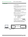
1 Virtual PLC
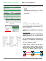
1.1 Description
As an option, the T200 and the Flair 200C can provide an
IEC 61131-3 programmable automation functions through
an embedded virtual machine (PLC).
The typical applications that can be created with a PLC
program :
• Automatic MV loop reconfiguration (Self Healing Grid).
• Automatism similar to the one embedded in T200
(ATS, BTA): ATS between 2 T200 or involving more
than two channels for example.
• Application of load-shedding.
• Any other automatism specific to a customer.
Warning: it is not possible to have simultaneously in the
product the option IEC 61131-3 PLC and the predefined
automation (ATS, Sectionalizer, ...).
A development platform allows creating, simulating and
testing programs using one of the following languages:
• SFC
– Sequential Function Chart
• FBD
– Function Block Diagram
• LD
– Ladder Diagram
• ST
– Structured Text
• Il
– Instruction List
This development platform is the software RTU Control
supplied with the product.
This platform can generate a program that will be executed
by a virtual PLC. This virtual PLC, embedded in the T200I,
exchange data in Read/Write mode with the T200I
software, allowing the exploitation of internal variables.
Variables exchanges
Embedded
PLC
RTU Control : development
platform
NT00320-EN-02
T200/F200C software
Programs
download
3
RTU Control & Formulas
RTU Control software
The details of programming with IEC61131-3 languages,
and the use of the platform will not be explained in this
document. The specific documentation can be accessed
through the RTU Control software.
However, we shall explain in this document how to
download and use a PLC program established in the Web
server of the T200/F200C and provide brief initial
instructions regarding the platform and management of the
parameters and associated variables.
4
NT00320-EN-02
RTU Control & Formulas
RTU Control software
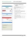
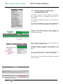
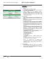
1.2 Installation of RTU Control
software
The “RTU Control” software is supplied with the unit. It is
included in the Easergy CD-Rom.
To install the software from the CD follow these
instructions:
NT00320-EN-02
Insert the CD-Rom supplied.
The software on CD must start automatically and a
window "Easer range - V8.xx" appears on screen.
Click on "Easergy series 3" link.
In the next window that appears, click on the link "RTU
CONTROL".
Software installation begins.
Then follow the various steps for installation without
changing the options proposed.
Wait for the end of the installation and then exit the
program.
5
RTU Control & Formulas
RTU Control software
Now that the RTU Control software is installed, download a
program established in the PLC.
There are two methods for downloading a PLC program
into the T200/F200C equipment:
•
Via the RTU Control platform, provided that the
RTU Control program is installed on the PC
connected to the T200/F200C and that the
equipment is powered up with the PLC function
started
•
Via the embedded Web server of the
T200/F200C, provided that the PLC program is
available in the form of a file with a *.cod extension
1.3 Downloading a program via RTU
Control software
This chapter shows the first method for downloading a
program from the PLC software "RTU control". This
assumes that the RTU Control software is installed on the
PC that is connected to the web server of T200/F200C, and
that the corresponding project is available.
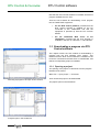
1.3.1 Opening a project
The opening of the project is carried out from the program
interface RTU Control:
Menu File → Open project → From Disk
Then choose the project to be downloaded
Selecting a program to be open in RTU Control
The project opens in the workbench.
Program open in the workbench
6
NT00320-EN-02
RTU Control & Formulas
RTU Control software
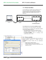
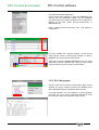
1.3.2 Connection to the PLC and download of
a program
Once the project is open, configure the connection to the
virtual PLC.
From the RTU Control workbench, open the following link :
Menu Tools → Communication parameters:
• Select "T5 Runtime"
• Enter the IP address of the device, followed by the
IP port number used by the Virtual Machine
(configured previously on the unit). The two fields
must be separated by the character ‘:’ (if IP port is
omitted, 1100 will be used)
• The example shows a configuration for a T200 with
the IP address 10.199.45.103 and the IP Port
number 1100
• Click on "Ok"
To connect the workbench to the T200/F200C and
download the application to the target, click on:
Menu Project / On line / Download application
To stop the application, click on the same button.
Note: this command can be done directly using the task
bar.
Button for downloading
application
The program is now ready to be used in the unit. It appears
now with the "running" status:
•
•
"Run" status in the RTU Control
workbench
In the RTU Control software
In the Embedded PLC page of the T200/F200C's
Web server
Note: We shall learn later the details regarding this
Embedded PLC page and how to access it.
"PLC Running" status in the "Embedded PLC" page of web
server
NT00320-EN-02
7
RTU Control software
RTU Control & Formulas
1.4 Shared variables
The embedded PLC handles internal variables and can
also share variables with the T200/F200C software.
A variable shared on the platform will be automatically
linked to a T200/F200C variable at start-up of the
application.
Variables exchanges
Embedded
PLC
RTU Control : development
platform
Programs
download
T200/F200C software
Inputs/outputs from internal
I/O or from an external PLC
The variables that can be shared are Global variables.
These variables can be used anywhere in the program;
The link between PLC variables and T200/F200C variables
can be done in different manners:
- strict equality of the name or using different names
- automatic creation of variables in the T200/F200C or
use of existing variables
- in case of creation, choice of exchange mode
(T200/F200C point of view)
1.4.1 Share a variable
From the workbench (disconnected from the device or
program stopped), right-click on a variable and select
"properties".
To share the selected variable with the T200/F200C
software :
• Check the box "Embed symbol"
• Select the profile “RCIO” in the profile list
• Complete following parameters depending on the
desired link mode.
8
NT00320-EN-02
RTU Control & Formulas
RTU Control software
UseExtName: Choice to use the name of the variable
declared in the workbench, if this one is different from the
one defined in the T200/F200C ("Yes"), or to force to use
the same name as the variable defined in the T200/F200C
("No", default value).
ExtName: Name of the T200/F200C variable associated to
the workbench variable. This parameter allows you to make
the relation between the variable of the T200/F200C and
the corresponding variable in the workbench, if they have
different name (used only if "UseExtName" = "Yes"). The
field length is limited to 15 characters.
MustExist: Choice to authorize creation of variable (No,
default value), or to impose using already existing
variables.
At start of the program, the T200/F200C checks all shared
variables. If the associated variable exists, the link is done.
If the variable does not exist, the T200/F200C can be
authorized or forbidden to create it.
This parameter allows a better control when the goal is to
link to an existing variable.
Mode : [Input/Output] Data exchange mode.
the Mode is used to determine whether from the PLC
application perspective, variables
are read-only or read-write. Variables defined as Inputs in
the PLC application will be read-only, i.e. changed
only by the RTU firmware. Variables defined as Outputs will
be read-write. For both Inputs and Outputs, the
current value will be read at the beginning of each PLC
cycle. Only Output variables will be updated at the end
of the PLC cycle.
Note that concrete variables (such as TSS) are
automatically read only.
VarDirection: [Signal/Command] Type of variable, from the
T200/F200C point of view. Used when a variable is created
by the T200/F200C (MustExist = no and corresponding
variable does not exist).
Variable defined as “Signal” will be created as an Input (DI
or AI). Variable defined as “Command” will be created as
an Output (DO or AO).
The commands can be controlled by the user via the web
interface or via the protocol (example: parameter, set point,
option).
Warning: the input/output notion from the T200/F200C
point of view is different from the PLC notion, where a
parameter is an ‘input’ of a function block for example.
After changes have been done to the variables
configuration, the program must be re-build and reloaded
into the device so that the modification is taken into
account.
NT00320-EN-02
9
RTU Control & Formulas
RTU Control software
Settings management for the shared variables can be done
via the browser profiles (icon "Open Profiles"):
This explorer allows to have a global view on the variables
associated to the RCIO profile, and to modify them.
"drag and drop" function allows to link easily a variable to a
profile.
10
NT00320-EN-02
RTU Control & Formulas
RTU Control software
1.4.2 Use of Arrays
Complex arrays of variables or structures can be used
internally by the PLC program.
In case of shared variables, the use of arrays is limited to
arrays of simple types, one dimension.
In that case, it is necessary to activate the option "Store
complex variables in a separate segment" in the options of
the project (Project\Settings…)
An array of N variables will be linked to N variables in the
T200/F200C software. The name of those variables will be
NameArray_@x with x from 1 to N.
Example: creation of arrays “State_Array” of 5 booleans
(BOOL), and “Parameters” of 2 integers (INT)
Variables created in the T200/F200C software are
State_Array_@1 to State_Array_@5 and Parameters_@1
to Parameters_@2
NT00320-EN-02
11
RTU Control & Formulas
RTU Control software
1.4.3 Miscellaneous
Advices concerning the names of the variables:
- Use only capital letters
- Do not give the same name to two different variables
- Do not use an integer as a name (for example "5")
Variable Types:
The T200/F200C supports the following types: BOOL,
SINT, INT, DINT, BYTE, WORD, REAL.
Warning: type must be compatible.
BOOL <--> TSS, TSL, DI or DO
SINT, INT, DINT, WORD, DWORD, REAL <--> TM, AI or
AO
DINT <--> Counters
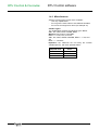
Important : the TSD/TCD are not binary but numeric
variables (BYTE), with three possible status :
TSD/TCD value
0
1
2
12
Status
Undefined
Off
On
NT00320-EN-02
RTU Control & Formulas
RTU Control software
1.5 PLC setting
In the same section "PLC" of the web server, other pages
are also linked to the PLC, notably those concerning the
configuration parameters.
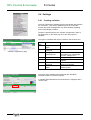
1.5.1 PLC Configuration
Click on the "Parameters" link to access the PLC
parameters configuration page.
This page contains informations about the operating status
of the virtual machine and the associated program, and
possible presence or error messages.
1.5.1.1
Virtual PLC IP port:
Number of the IP port that will be used by the PLC program
(RTU CONTROL).
Default value: 1100
1.5.1.2
Cycle time:
This value is in milliseconds is a period which correspond
to the cycle of the virtual machine. This value in ms must
be defined between 100 and 10000ms (10 seconds).
1.5.1.3
Program:
Name of the program loaded and executed by the virtual
machine, including all such programs in the flash memory.
The T200/F200C help maintain multiple programs in
memory, but only one can be executed.
(See chapter "Downloading a program via the embedded
Web server" for more information.)
Embedded PLC configuration page
NT00320-EN-02
Note: the option to start the PLC is not configurable. This
start-up is always performed as a "Cold start".
Consequently, all the internal variables of the PLC will be
reset to their initial values during start-up period.
The values of “Retain” variables are not used.
13
RTU Control & Formulas
RTU Control software
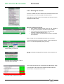
1.5.2 Downloading a program via the
embedded Web server
This chapter explains the second method to download a
PLC program from the embedded Web server of
T200/F200C.
To be able to download the program, you need first to get
the *.cod file.
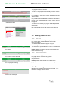
To access the Embedded PLC page of the embedded Web
server, click on the corresponding link ("Embedded PLC").
If RTU Control software has never been activated in
equipment, enter the activation code (provided by
Schneider Telecontrol).
Page for RTU Control software activation
Then click on the "Flash Memory" link to access the PLC
file and memory management page
This page manages the programs of the application to be
uploaded or already uploaded in Flash memory of the
device.
Click on the "Browse" button to define the location of the
PLC program file (extension “*.cod”) to be downloaded.
Then click on the "Submit" button to recognize the program
in the virtual PLC.
"Flash memory" page
14
NT00320-EN-02
RTU Control & Formulas
RTU Control software
The program is ready to be used.
The name of the program is then displayed in the "Contain"
part with an indication of the file size.
It is possible to erase this program in the PLC via the
"Delete" button.
It is possible to download this file to the PC's hard disk in
the form of a *.cod extension, by clicking on the name of
the program.
"Flash memory" page
The memory size used by the program is also displayed as
a percentage.
It is recommended to format the memory before first use,
via the "Format" button.
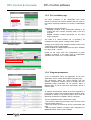
1.5.3 Working state of the PLC
1.5.3.1
PLC status
In the "Embedded PLC/Configuration" page, the first line of
the "Working state" section indicates if the module is
running or stopped.
The module can be started or stopped using the
corresponding buttons.
This parameter is saved (if the RTU re-start, the module will
be in the last state)
PLC stopped
Note: to allow the connection with the virtual machine, the
module must be running.
1.5.3.2
PLC running, program stopped
Virtual machine state
If the module is running, a second line shows the state of
the virtual machine, executing the program.
The program can be started or stopped from the interface
using the buttons.
Note: depending on the number of variables in the
program, the start-up delay can be shorter or longer.
PLC and program running
1.5.4 Error messages
If the start of the module or the program has failed, one or
more error messages can be shown.
Different error messages
NT00320-EN-02
15
RTU Control & Formulas
RTU Control software
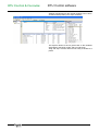
1.5.5 PLC variables page
The page "Variables" of the "Embedded PLC" menu
permits to manage the internal variables that are used for
the internal exchange between PLC and the T200/F200C
unit.
Variables that can be shared are:
• Existing variables of the T200/F200C defined to be
shared with RTU Control, because used in the PLC
program.
• Virtual variables created specifically for the RTU
Control program.
The value of a virtual variable can, if necessary, be
modified in this page via the "Change Value" button.
"Variables" page
Clicking on the name of the variable provides access to the
configuration page for that variable.
Virtual variables are differentiated from the other variables
by a topic value = "Virtual".
Except for the Topic value, the configuration of these
variables is identical to the other types of T200/F200C
variables. See section 2.4.1 Creating variables.
Page of configuration for a virtual variable
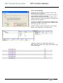
1.5.6 Program parameters
A set of parameters which are applicable for the PLC
Application can be created and modified using this page.
The parameters values are saved together with the
Easergy configuration without having to change the PLC
Application.These parameters can be numeric, within a
defined range, or part of a list which associates a text to a
numeric value.
To transfer the parameter values to the PLC application, it
is necessary to define virtual Analog Output variables. Each
parameter is linked to one Analog Output which must be
defined as a shared I/O variable in the PLC program.
Example of PLC parameters
16
The PLC parameter value is written to the AOs:
- when the RTU starts up (technically when the PLC virtual
machine thread starts up)
- after new values are entered on the PLC parameter web
page
- after the system detects a change in the configuration for
MODBUS master and/or virtual variables.
NT00320-EN-02
RTU Control & Formulas
RTU Control software
Up to 20 parameters can be defined. For each, the
following parameters can be defined:
- the name
- the value
- the Associated AO (the AO must be previously defined)
- the type “Numeric” or “List”
- the possible range of value (Min/Max)
- for a parameter of type “List”, add and edit the possible
items of the list
1.5.7 Peer to Peer configuration page
The Peer-to-peer feature allows direct “side-ways”
communication between two or more RTUs independently
of the “upwards” communication to a SCADA system.
The RTUs must be installed on the same TCP/IP network
(Ethernet or GPRS/UMTS).
This page shows the configuration of the transfer tables
that are used to send messages between two neighbouring
equipments.
Peer to Peer principle:
The peer to peer communication can copy the values of a
set of variables from one RTU to another using the
MODBUS TCP protocol and the “write multiple registers
command. This is similar to the concept of a “dataset” in
other protocols”.
Each dataset is defined as an exchange table within both
peer devices. On the sending device, the table is defined
as type “Write” and on the receiver it is defined as type
“Read”. Each exchange table defines a range of MODBUS
addresses. Variable are part of the dataset if they have a
“peer-to-peer” address within the range.
For “Write” tables, the variables may have any type. For
“Read” tables the variables must be either DO or AO types.
The PLC program can launch the sending of the “Write”
tables, and is warned when the “Read” tables are updated.
The process uses additional variables to indicate the
success or failure of each message. These can be used by
the PLC program to retry messages if needed.
NT00320-EN-02
17
RTU Control & Formulas
RTU Control software
Configuration:
Up to 6 tables can be defined.
For each table,
- Name
- Transfer Type: Inactiv, Write or Read
- Start address: local MODBUS address that correspond
to the first variable of the table
- Length: Number of 16 bit MODBUS registers.
Maximum 6. Digital variables are mapped to a single
bit. Analog variables use one 16 bit register. The
“length” value must be the same in the “Write” table
and in the “Read” table.
For type “Write”:
- Slave number: correspond to the slave index on the
Slaves configuration page (where its IP address will be
defined)
- Distant address: MODBUS address on the slave where
the table will be written
- SendDataActive Index: DO index (control variable).
This is the index of the DO variable to be activated by
the PLC application to request the firmware to write the
content of the table into the distant device. This is reset
automatically by the firmware when the transfer is in
progress.
- SendDataInProgress DO index (control variable). This
is the index of the DO variable that indicates the write
process is in progress for this table. It is reset
automatically when the transfer is complete or times
out. Useful for commissioning
- SendDataResult Index: index of an AO (control
variable) that shows the status of the transfer.
Possible values of the AO are:
0: Operation successful
1: Invalid MODBUS function
2: Invalid address
3: Invalid data
15: Communication Error – problem creating a TCP
connection
16: Communication error – request or reply timed out
20: Set when a message is in progress
Codes 1,2,3 indicate that the message was
successfully delivered but that the receiving device
rejected it. This usually means some sort of
configuration error.
For type “Read”:
- ReceiveDataValid Index: DO index (control variable).
This is the index of a DO variable that is set when new
data has been written by a distant device. It should be
reset by the PLC application.
18
NT00320-EN-02
RTU Control & Formulas
RTU Control software
Protocols and Variable Addresses
As the peer-to-peer feature is using the MODBUS TCP
protocol, both the MODBUS master, and the MODBUS
TCP slave protocol is always enabled on the equipment in
addition to the main “slave” protocol (IEC101/104 or
DNP3/DNP3 IP).
Each of these protocols have their own
configuration.
web pages for
For each variable, the “External address” is used by the
main protocol, and the “Peer-to-peer address” is used in
MODBUS TCP for the peer-to-peer feature.
If the main protocol is MODBUS/MODBUS TCP, the same
addresses (external address) are used for both Scada
communication and peer-to-peer communication.
1.5.8 PLC debug page
The PLC trace can be used to check that the RTU Control
program is running correctly and that the variables have
been downloaded into the equipment without errors.
In normal operation, it is not necessary to control program
execution. It's only in case of abnormal behaviour of the
PLC that the control of its operation can be useful.
NT00320-EN-02
19
RTU Control & Formulas
RTU Control software
1.6 Examples
Some demonstration projects are provided as
examples. They are part of RTU Control installation
and are included in the in the folder "RTU
CONTROL\Samples\Easergy".
These projects allow for example to show the link
between RTU Control and the T200 variables and
also the management of TSD/TCD. They include
corresponding T200 or F200C configurations in a
dedicated folder
These projects are dedicated to the demonstration
and are not supported by the technical support.
No responsibility is assumed by Schneider Electric
for any consequences arising out of the use of
these programs.
20
NT00320-EN-02
RTU Control & Formulas
Formulas
2 Calculation formulas
2.1 Presentation
Contrary to the PLC which is an option for the T200
and Flair 200C, the calculation formulas are
provided as standard with the basic T200.
The calculation formulas allow arithmetic and
combinational operations between variables.
The formulas make it possible to:
• Perform mathematical calculations based
on physical measurements (consumption,
conversions, etc.).
• Create
personalized
indications
(combinations of variables, grouped faults,
etc.).
• Define new type of automation for
controlling or monitoring (change over,
etc…).
A formula is associated with a variable.
Following its execution, the formula will assign the
value obtained to the associated variable.
Its value is updated at each execution of the
formula, according to a configurable cycle time
(minimum cycle time = 100 ms).
NT00320-EN-02
21
RTU Control & Formulas
Formulas
2.2 Syntaxes and rules
The formulas use a natural and intuitive syntax that
combines references with measurement values
(variables, historians, etc), literal expressions
(constants, operators, etc) and function calls (min,
max, delta, etc).
The user does not need to worry about data
formats; the interpreter takes care of the
conversions. This makes it possible to combine
logical and mathematical operations: (B > 3)* C,
(B>3) is a logical expression (true (1) or false (0)).
The formulas only make sense if at the end of their
execution the value obtained is allocated to a
variable (or to a database cell). It should be
understood that a formula is not a script
language; there is no concept of loops (for, while)
or instruction jumps (goto, if..then). However, there
is a conditional operator that allows the allocating of
such and such a value according to a logical
expression.
The formulas take into account the case (lowercase
or uppercase) of the operands and functions. The
maximum length of a formula is 200 characters.
A formula can accept up to 50 elements (operands,
operators…).
A formula may be split into several "sub-formulas"
separated by a semi-colon (the comma is
reserved for separating a function's
parameters).
Each "sub-formula" is executed successively in
their order of writing during the same processing
cycle.
2.2.1 Operands
2.2.1.1
Numerical constants (integers, decimal
numbers):
The numbers may be positive or negative, whole or
decimal and/or exponent: 123, -45.1, 12.5E3, etc.
To enter a hexadecimal number, its value must be
prefixed with the symbol $ (or the letter H), for
example $10 (or H10).
For "decimal" values, the decimal separator is the
point.
The type of value (integer, word, IEEE) is
automatically determined by analysis of the formula.
22
NT00320-EN-02
RTU Control & Formulas
Formulas
2.2.1.2
Character strings:
A character string must be entered between single '
quote marks, for example 'my string'.
Character strings are used to reference certain
function parameters or names of tables or database
columns.
2.2.1.3
Variables:
By entering the name of a variable (without quote
marks), the operand will be interpreted as the value
of the variable at the time of execution. The type of
value is that of the variable.
Warning, the name of a variable used with a
formula must not contain spaces.
2.2.2 Operators
2.2.2.1
+
*
/
%
**
Mathematical:
Addition
Subtraction
Multiplication
Division (dividing by zero causes an execution error)
Modulo: Remainder of the whole division (whole numbers)
Power: A**B = A exponent B = AB
2.2.2.2
Logical:
&& Logical AND
A && B = true if A = true AND B = true, otherwise false
## Logical OR
A || B = true if A = true OR B = true, otherwise false
||
^^ Logical
A ^^ B = true if (A = true AND B = false) OR (A = false
AND B = true)
EXCLUSIVE
OR
!
! A = true if A = false
Logical NOT
Remark : the symbol « | » is obtained by pressing simultaneously the keys [AltGr]
and [6] from the keyboard.
2.2.2.3
&
I
#
^
~
<<
>>
NT00320-EN-02
Binary:
Bitwise AND
Bitwise OR
$AA & $55 = $00
$AA | $55 = $FF
Bitwise EXCLUSIVE
OR
Bitwise NOT
(Complement to 1)
Shift left
Shift right
$AA ^ $A5 = $0F
~A, inverts all the A bits, those at 1 change to 0
and vice versa
A << B, shifts the A bits by B bits to the left
A >> B, shifts the A bits by B bits to the right
23
RTU Control & Formulas
Formulas
2.2.2.4
Comparisons:
=
==
!=
<>
>
<
>=
<=
2.2.2.5
Equal
Different
Greater than
Less than
Greater than or equal
to
Less than or equal to
Allocation operator
The operator := is used to allocate a value to a
variable:
Example: "mavar := 2".
The user does not need to worry about the
destination data format as the conversions are
automatic.
In the case of an input/output peripheral variable,
allocation will cause the sending of an order of
writing to the peripheral when the formula is
executed.
2.2.2.6
Conditional operator
The operator (expr) ? A : B returns A if expr is true,
otherwise B.
expr must be a boolean expression.
For example:
A := (B>C) ? D : E; will allocate D to A if B is greater
than C, otherwise it will allocate E to A.
It is of course possible to use brackets to create
more complex expressions.
The same principle applies to operations:
A + ((B>C) ? D : E) is worth A + D if B > C,
otherwise it is worth A + E.
The conditional operator can also be used for
allocation:
((B > C) ? D : E) := A;
in this case, if B > C, D is allocated with the value
A, otherwise it is E that is allocated with the value
A.
24
NT00320-EN-02
RTU Control & Formulas
Formulas
2.2.2.7
Order of importance of operators and
use of brackets
The decreasing order of importance in the
execution of an expression’s operations is the
following:
Function
Fcn ( )
P0 = max priority
Positive sign
+ (Var)
P1
Negative sign
Logical NOT
Complement to 1 *
Power
Multiplication
- (Var)
!
~
**
*
P2
P3
Division
Remainder *
Addition
/
%
+
P4
Subtraction
Shift left *
Shift right *
Bitwise AND *
<<
>>
&
P5
Bitwise OR *
Bitwise EXCLUSIVE
Logical AND
I/#
^
&&
P6
Logica OR
II/##
Logical EXCLUSIVE
^^
Test equal to
=
Test less or equal to
<=
Test great or equal to
>=
Test less than
<
Test greater than
>
Test different from
!=/<>
Allocation
:=
"*" : Operation on integer only (manipulation on bits)
NT00320-EN-02
P7 = min priority
25
Formulas
RTU Control & Formulas
2.3 Functions
The functions’ arguments may be any kind of operand, but also
mathematical or logical expressions or function results. This
makes it possible to link together several function and operation
calls.
", … )": the three small dots indicate functions with a varying
number of arguments.
"[x]": the square brackets refer to one (or several) operational
argument(s).
3.1
Mathematical functions
Excluding indications to the contrary, the data format of the
values returned by these functions is IEEE (floating simple
precision)..
2.3.1.1
abs(x)
Returns the absolute value of its argument x
The type of data returned by the function is the same as that of x.
Example:
Abs(VAR1*3)
2.3.1.2
sqrt( x )
Returns the square root of x.
If x is less than zero, the operation causes an execution error.
2.3.1.3
log( x )
Returns the Napierian logarithm of x.
If x is less than or equal to 0, the operation causes an execution
error.
2.3.1.4
log10( x )
Returns the logarithm in base 10 of x.
If x is less than or equal to 0, the operation causes an execution
error.
2.3.1.5
exp( x )
Returns the exponential of x. exp( log(x) ) = x.
2.3.1.6
pow( x, y)
Returns x to the power of y. pow(x, y) = x ** y = xy.
2.3.1.7
intg( x )
Returns the whole part of x. For example, intg( 12.46 ) = 12.
The value returned is an integer (INT32).
2.3.1.8
rand( x )
Returns a random whole number greater than or equal to 0 and
less than x.
The value returned is a double word (DWORD).
26
NT00320-EN-02
Formulas
RTU Control & Formulas
2.3.2 Statistical functions:
2.3.2.1
mini( A, B, … )
Returns the argument whose value is the smallest.
This function must include at least two arguments.
Note that this function returns not only the value of the argument
but also its reference. This means it is possible to combine it with
an allocation operation:
mini( VAR1, VAR2, VAR3 ) := 4; with VAR1, VAR2, VAR3 of the
variable references, if VAR3 has the minimum value, this variable
will then be allocated with the value 4.
2.3.2.2
maxi( A, B, … )
Returns the argument whose value is the largest.
This function must include at least two arguments.
As with mini, this function returns the argument reference.
2.3.2.3
pmini( A, B, … )
Returns the position (from 0) of the argument whose value is the
smallest.
This function must include at least two arguments.
2.3.2.4
pmaxi( A, B, … )
Returns the position (from 0) of the argument whose value is the
largest.
This function must include at least two arguments.
2.3.2.5
sum( A, B, … )
Returns the value of the sum of the arguments.
This function must include at least two arguments.
2.3.2.6
avg( A, B, … )
Returns the value of the argument's average.
This function must include at least two arguments.
NT00320-EN-02
27
Formulas
RTU Control & Formulas
2.3.3 Logical functions:
2.3.3.1
pulse( X, T0, T1 )
X is a boolean value. T0 and T1 are numbers of seconds.
On front edge of X (transition from 0 to 1), after T0 seconds, the
function returns true (1) for T1 seconds. The rest of the time it
returns false (0).
1
X
1
pulse( X, T0, T1 )
T1
T0
2.3.3.2
delay( X, T0 )
X is a boolean value. T0 is a number of seconds.
The function copies the value of X is shifted in time by T0
seconds.
X
T
delay( X, T0 )
T
T0
2.3.3.3
hold( X, T1 )
X is a boolean value. T1 is a number of seconds.
The function returns true for at least T1 seconds on a front edge
(transition from 0 to 1) of X. If X stays at 1 (true) for more than T1
seconds, the hold function returns true during this time.
X
hold( X, T1 )
T1
2.3.3.4
T1
tempo( X, T2 )
X is a boolean value. T2 is a number of seconds.
The function returns true if X moves to 1 for at least T2 seconds.
After this time, the function returns true as long as X is at true.
X
t
Time out ( X, T2 )
28
T2
t < T2
NT00320-EN-02
Formulas
RTU Control & Formulas
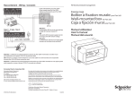
2.3.3.5
pwm( T, R )
The function returns a boolean value at the rhythm of a PWM
signal of period T and cyclical ratio R as a percentage. R must be
between 0 and 100%.
T0
T1
R = 33 %
T1 = 33% * T
T0 = (100 – 33%) * T
R = 50 %
T1 = 50% * T
T0 = (100 – 50%) * T
T1
T0
R = 66 %
T1 = 66% * T
T0 = (100 – 66%) * T
T
2.3.3.6
iswithin( X, min, max )
returns a boolean value that is worth true if (X >= min) AND (x <=
max), and otherwise false.
NT00320-EN-02
29
Formulas
RTU Control & Formulas
2.3.4 Time / Date and time functions:
The TIME_T format is a data format that allows the recording of a
date/time couple in numbers of seconds since a single reference
(1st January 1970 at 00:00:00).
The days of the week are associated with the following values:
1 = Sunday, 2 = Monday, 4 = Tuesday, 8 = Wednesday, 16 =
Thursday, 32 = Friday, 64 = Saturday.
2.3.4.1
dt( [[T], X] ) or now( [[T], X] )
Without an argument, the function returns the current date and
time as TIME_T.
With T as TIME_T and X, T serves as a reference for the
argument X
With X only, the current date and time functions serve as
references for the argument X
if X = 1 or 'Y', returns the year in 4 figures
if X = 2 or 'M', returns the month (from 1 to 12)
if X = 3 or 'D', returns the day of the month (from 1 to 31)
if X = 4 or 'H', returns the time according to the 24Hr clock (from 0
to 23)
if X = 5 or 'm', returns the minute (from 0 to 59)
if X = 6 or 's', returns the second (from 0 to 59)
if X = 7 or 'd', returns the day of the week (1, 2, 4, 8,16, 32, 64)
if X = 8 or 'p', returns 0 if the time is before midday (AM), 1 for the
afternoon (PM)
if X = 9 or 'h', returns the time according to the 12Hr clock
if X = 10 or 'y', returns the year in 2 figures
2.3.4.2
time( X [, F] )
With X only, if X is a character string, the function converts into
TIME_T format the date and time corresponding to X according to
the default date and time format. If X is numerical the function
converts this number into TIME_T.
With X and F, X must be a character string, F is also a character
string that defines the read format for the date and time. The
function therefore returns date X as TIME_T according to format
F.
F is in the form 'd/m/y H:M:S' with:
d = the day of the month (from 1 to 31)
m = the month of the year (from 1 to 12)
y = the year in 2 figures
Y = the year in 4 figures
H = the time according to the 24hr clock
h = the time according to the 12hr clock
M = the minute (from 0 to 59)
S = the second (from 0 to 59)
30
NT00320-EN-02
Formulas
RTU Control & Formulas
2.3.4.3
isweek( [X] )
If X (optional) is absent, the function returns the boolean value
true if the current date is a working day (from Monday to Friday
inclusive).
If X is of type TIME_T, the function returns true if the date X is a
working day. Otherwise X refers to a number for the day of the
week and the function returns true if day X is a working day.
2.3.4.4
deltats()
Returns the time in SECONDS between two executions of the
formula.
This function is very powerful as it allows the creation of
integrations, differential coefficients, etc.
It is based on the system’s real time clock.
2.3.4.5
deltatms()
Returns the time in MILLISECONDS between two executions of
the formula.
This function is very powerful as it allows the creation of
integrations, differential coefficients, etc.
It is based on the CPU’s quartz clock. This means that it is
relatively inaccurate over the long term
2.3.5 Other functions:
2.3.5.1
bounds( X, min, max )
Returns the value of X limited by min and max.
If X is less than min, returns min; if X is greater than max, returns
max; otherwise returns X.
2.3.5.2
delta( X ) or deltav( X )
Returns the difference between the value of X on the previous
execution of the formula and the current value of X. The period for
calculating the difference in X is therefore the execution period of
the formula. See also deltats() and deltatms().
2.3.5.3
switch( X, A0, A1 [, A2, …]) or cond( X, A0, A1 [, A2,
…])
X must be a positive whole value.
This function must include at least three arguments.
If X = 0, the function returns the argument A0, if X = 1, returns A1,
if X = 2, returns A2, etc.
If X < 0, the function returns the argument A0, if X is greater than
the number of arguments, the most recent is returned.
NT00320-EN-02
31
Formulas
RTU Control & Formulas
2.4 Settings
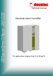
2.4.1 Creating variables
The user must declare variables that are specifically associated to
the "Formulas". They will be updated only by the "Formulas"
function but will be managed like any other variables regarding
protocol and display of status.
Creation is performed from the "Variable Configuration" page of
the Web server, in the same way as for the other types of
variables.
The types of variables that can be created for the functions are:
"Variable configuration" page
Variable Use
type
DI
Single remote
signal
DO
Single remote
command
AI
Analogue
measurements
AO
CNT
TCD
TSD
Description
Single bit indication
Single bit command
Analogue measurements
performed by the T200/F200C
(currents, voltages, etc.)
Analogue command Analogue writing
Counter
Change of state counter on
single bit
Double remote
Double command on
command
switch/circuit breaker
Double remote
Indication of switch/circuit
signal
breaker position
The name of the variables associated with the calculation
formulas should not contain any space
A variable associated with a formula should be configured with a
"Virtual" topic.
32
NT00320-EN-02
RTU Control & Formulas
Formulas
2.4.2 Entering the formula
Once the variable has been created, the associated formula must
be entered in the "Formulas" page of the Web server
This page can include at most 100 formulas. 20 formulas can be
displayed simultaneously.
Example of formula defined
Rules for entering the formula:
• Each formula should start with “name_of_the_variable:="
• No space is accepted in the name of the variables.
• The content of the formula with the operands and
operators is defined after the sign "…:="
• The case must be complied with for names of variables
and operands.
Each formula can be activated/deactivated via a check box.
A formula refresh period should be defined. A period defined as
"Auto." = the shortest possible period (100 ms).
Refresh delay of a formula
An error message is displayed if the syntax of the formula is not
correct.
Example of error message in case of
incorrect input in formula
The result of the formula can be viewed in the "Monitoring" page
It corresponds to the state of the variable associated with the
formula which corresponds to its result.
Formula result in "Monitoring" page.
NT00320-EN-02
33
RTU Control & Formulas
34
Personal notes
NT00320-EN-02
RTU Control & Formulas
NT00320-EN-02
Personal notes
35
Schneider Electric Industries SAS
En raison de l’évolution des normes et du matériel, les caractéristiques
indiquées par les textes et les images de ce document ne nous
engagent qu’après confirmation par nos services.
Schneider Electric Telecontrol
839 chemin des Batterses
Z.I. Ouest
01700 St Maurice de Beynost
Tel : +33 (0)4 78 55 13 13
Fax : +33 (0)4 78 55 50 00
As standards, specifications and designs change from time to time,
please ask for confirmation of the information given in this publication.
Debido a la evolución de las normas y del material, las características y
dimensiones indicadasen el texto y las imágenes nos comprometen
solamente previa confirmación de nuestros servicios.
http://www.schneider-electric.com
E-mail : [email protected]
NT00320-EN-02
08/2013
Publication, production and printing : Schneider Electric Telecontrol
Made in France - Europe