1
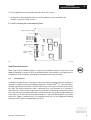
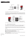
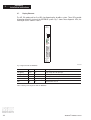
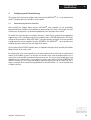
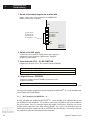
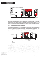
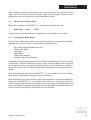
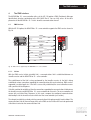
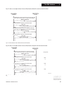
MOVIDYN® Servo Controller AFI 11A INTERBUS Option User Manual Edition 02/96 0922 7717 / 0499 16/042/95 P reface P reface This AFI 11A INTERBUS Option User Manual describes the procedure for installing the AFI 11A INTERBUS option pcb in the servo controller and for commissioning the MOVIDYN® 51.. servo controller when connected to an INTERBUS fieldbus system. In addition to describing all the settings on the fieldbus option pcb, this manual further discusses the various options for connecting the servo controller to INTERBUS in the form of brief commissioning examples. In addition to this AFI 11A INTERBUS Option User Manual, you should order the following more detailed documentation on fieldbuses in order to enable the MOVIDYN® 51.. to be connected simply and efficiently to the INTERBUS fieldbus system - MOVIDYN® 51.. Fieldbus Unit Profile Manual - MOVIDYN® 51.. Parameter List The MOVIDYN ® 51.. Fieldbus Unit Profile Manual gives a detailed description of control concepts and discusses various application options in the form of brief examples. The MOVIDYN ® 51.. Parameter List contains a list of all the servo controller parameters that can be read or written via the various communication interfaces such as the RS-232, RS-485 and via the fieldbus interface. MOVIDYN ® INTERBUS AFI11A 3 Contents Contents Important Instructions . . . . . . . . . . . . . . . . . 1. Introduction . . . . . . . . . . . . . . . . . . . . 2. Assembly / Installation Instructions . . . . . . . . 2.1. Scope of Delivery . . . . . . . . . . . . . . . 2.2. Supported Servo Controller Types . . . . . . 2.3. Fitting the Option PCB . . . . . . . . . . . . 2.4. Pin Assignment . . . . . . . . . . . . . . . . 2.5. Screening and Laying of the Bus Cables . . . 2.6. Setting the Process Data Length . . . . . . . 2.7. Display Elements . . . . . . . . . . . . . . . 3. Configuring and Commissioning . . . . . . . . . . 3.1. Commissioning of the Servo Controller . . . . 3.1.1. Bus Topologies with MOVIDYN 51.. . . . . . . 3.1.2. Direct Connection to DCB Master Modules . . 3.1.3. Connecting to DAB Master Modules . . . . . . 3.1.4. Integration in 8-Wire Remote Bus Systems . . 3.2. Servo Controller Module Identity . . . . . . . 3.3. Configuring the Master Module . . . . . . . . 3.3.1. Configuring for 1 Process Data Word . . . . . 3.3.2. Configuring for 2 Process Data Words . . . . 3.3.3. Configuring for 3 Process Data Words . . . . 4. The P MS Interface . . . . . . . . . . . . . . . . 4.1. PMS Services . . . . . . . . . . . . . . . . . 4.1.1. Initiate . . . . . . . . . . . . . . . . . . . . . 4.1.2. Abort . . . . . . . . . . . . . . . . . . . . . . 4.1.3. Reject . . . . . . . . . . . . . . . . . . . . . 4.1.4. Identify . . . . . . . . . . . . . . . . . . . . . 4.1.5. Get-OV . . . . . . . . . . . . . . . . . . . . . 4.1.6. Status . . . . . . . . . . . . . . . . . . . . . 4.1.7. Read . . . . . . . . . . . . . . . . . . . . . . 4.1.8. Write . . . . . . . . . . . . . . . . . . . . . . 4.2. Object List . . . . . . . . . . . . . . . . . . . 4.2.1. Object Description of the Drive Parameters . . 4.2.2. ”Download Parameter Block” Object . . . . . 4.2.3. ”Universal Write Parameter” Object . . . . . . 4.2.4. ”Universal-Read” Functionality Objects . . . . 4.2.4.1. ”Universal Read Pointer” Object . . . . . . . . 4.2.4.2. ”Universal Read Data” Object . . . . . . . . . 5. P arameter Adjustment Return Codes . . . . . . . . 5.1. Internal Communications Error . . . . . . . . 6. AFI 11A Option Technical Data . . . . . . . . . . . Appendix A . . . . . . . . . . . . . . . . . . . . . . Index . . . . . . . . . . . . . . . . . . . . . . . . . 4 . . . . . . . . . . . . . . . . . . . . . . . . . . . . . . . . . . . . . . . . . . . . . . . . . . . . . . . . . . . . . . . . . . . . . . . . . . . . . . . . . . . . . . . . . . . . . . . . . . . . . . . . . . . . . . . . . . . . . . . . . . . . . . . . . . . . . . . . . . . . . . . . . . . . . . . . . . . . . . . . . . . . . . . . . . . . . . . . . . . . . . . . . . . . . . . . . . . . . . . . . . . . . . . . . . . . . . . . . . . . . . . . . . . . . . . . . . . . . . . . . . . . . . . . . . . . . . . . . . . . . . . . . . . . . . . . . . . . . . . . . . . . . . . . . . . . . . . . . . . . . . . . . . . . . . . . . . . . . . . . . . . . . . . . . . . . . . . . . . . . . . . . . . . . . . . . . . . . . . . . . . . . . . . . . . . . . . . . . . . . . . . . . . . . . . . . . . . . . . . . . . . . . . . . . . . . . . . . . . . . . . . . . . . . . . . . . . . . . . . . . . . . . . . . . . . . . . . . . . . . . . . . . . . . . . . . . . . . . . . . . . . . . . . . . . . . . . . . . . . . . . . . . . . . . . . . . . . . . . . . . . . . . . . . . . . . . . . . . . . . . . . . . . . . . . . . . . . . . . . . . . . . . . . . . . . . . . . . . . . . . . . . . . . . . . . . . . . . . . . . . . . . . . . . . . . . . . . . . . . . . . . . . . . . . . . . . . . . . . . . . . . . . . . . . . . . . . . . . . . . . . . . . . . . . . . . . . . . . . . . . . . . . . . . . . . . . . . . . . . . . . . . . . . . . . . . . . . . . . . . . . . . . . . . . . . . . . . . . . . . . . . . . . . . . . . . . . . . . . . . . . . . . . . . . . . . . . . . . . . . . . . . . . . . . . . 5 6 8 8 8 8 9 10 11 12 13 13 14 15 15 16 17 17 18 19 20 21 21 21 22 22 22 22 22 22 22 23 23 24 25 26 28 28 30 30 31 32 33 MOVIDYN ® INTERBUS AFI11A Important Instructions Important Instructions ● P lease read this user manual carefully and thoroughly before installing and commissioning the MOVIDYN® servo controller with INTERBUS option. It is assumed that engineers performing the work described within this user manual are familiar with the MOVIDYN® servo controller and especially with its installation and commissioning instructions. ● Safety Instructions Strictly follow all warnings, precautions and safety instructions contained in this user manual. Electrical hazard, e.g. live working Mechanical hazard, e.g. work on hoist Important note for safe and trouble-free operation of the driven machine/system, e.g. presettings prior to commissioning. Failure to do so could result in serious injury to persons or damage to equipment. ● General safety instructions regarding bus systems: You are operating via a communications system which allows the MOVIDYN® servo controller to integrate within a wide range of equipment variations. As with all bus systems there exists a danger of unseen changes to parameters (in reference to the controller) and thereby controller behaviour. This can lead to unexpected (not uncontrolled) system behaviour. ● Cross-references are identified in this user manual by an →, which means for example: (→ MD_SHELL) You can refer to the MD_SHELL user manual to complete the instructions or find more detailed information there. (→ Sec. x.x) You will find additional information in section x.x of this user manual. ● Each unit is manufactured and tested in conformance with the applicable technical documentation by SEW-EURODRIVE. In the interest of technical progress, technical data and designs as well as the user interface described herein are subject to change without notice. Follow the instructions contained in this manual to insure trouble-free operation and to satisfy eventual warranty claims. This manual also contains important service information. We therefore advise keeping it close to the unit. MOVIDYN ® INTERBUS AFI11A 5 1 Introduction 1. Introduction Thanks to its high-performance, universal fieldbus interface, the MOVIDYN® 51.. servo controller with the AFI 11A option enables connections to be made with higher-level automation systems via the open and standardized serial INTERBUS sensor/actuator bus system. INTERBUS INTERBUS is a high-speed universal sensor/actuator bus system for decentralized peripheral areas. The INTERBUS moves the input/output level away from the higher-level control system to the machine or the installation level. The INTERBUS is an open bus system, which is already supported by more than 200 equipment manufacturers from the most diverse industries. INTERBUS specifications are set forth in the DIN 19258 standard. I NTERBUS bus functions comprise a process data and a parameter data channel offering easy, user-friendly control and parameter adjustment of intelligent digital actuators such as, e.g., servo controllers. MOVIDYN® 51.. and INTERBUS The controller unit profile for INTERBUS mode, i.e. the way the servo controller operates and responds when in INTERBUS mode, is independent of the type of fieldbus, and thus consistent for all fieldbus types. This allows the user to develop his drive applications independent of a particular fieldbus or change to another bus system, e.g. the open standardized PROFIBUS-DP/FMS (AFP 11A option) fieldbus system. MOVIDYN® 51.. offers digital access to all drive parameters and functions via the INTERBUS interface. The servo controller is controlled by the high-speed cyclic process data. This process data channel provides the facility to specify setpoints such as setpoint speeds, ramp generator times for acceleration and deceleration etc., as well as various drive functions such as enable, controller inhibit, stop, rapid stop, etc. to be triggered. This channel can also be used to read back actual values from the servo controller, such as actual speed, current, unit status, error number or reference messages. Whereas process data are generally exchanged in cycles, the drive parameters can only be read and written acyclically via the READ and WRITE services. This exchange of parameter data enables applications where all major drive parameters are stored in the higher-level automation unit to be implemented, thus avoiding manual adjustment of parameters on the servo controller itself, which can often be very time-consuming. 6 MOVIDYN ® INTERBUS AFI11A Introduction Control INTERBUS INTERBUSMaster -S Master Servo Controllers Servoumrichter Steuerung S EW S EW S EW E U R O DR IV E EURODRIVE E URODRIVE SEW SEW EURODRIVE EURODRIVE P P P P P Modul Ident: ABCDFE Modul Ident: AB CD F E Modul Ident: AB CDF E Modul Ident: AB CDF E Typ: Modul Ident: AB CDF E PHOENIX CONTACT IN TERBUS Typ: 1 PHOENIX CONTACT IN TERBUS Typ: PHOENIX CONTACT IN TERBUS Typ: PHOENIX CONTACT IN TERBUS Typ: PHOENIX CONTACT INTERBUS I N OUT Input modules Ein- //Output Ausgabemodule INTERBUS-S MD0337ED Fig. 1: INTERBUS with MOVIDYN ®51.. The INTERBUS option pcb is designed so that all INTERBUS specific settings, such as the process data length, can be made on the option pcb by means of a hardware switch. These manual settings enable the servo controller to be integrated into the INTERBUS system and switched on in a very short space of time. Parameters can be set fully automatically by the higher-level INTERBUS master (parameter download). This forward-looking version offers benefits of a shorter commissioning period for the plant as well as simpler documentation of the application program, as all major drive parameter data can now be recorded directly in the control program. The use of a fieldbus system in drive technology requires additional monitoring functions, such as fieldbus timeout or special emergency stop concepts. The monitoring functions of the MOVIDYN® 51.. can be matched to the specific application for which it is to be used. This feature enables you, for instance, to specify which error response the servo controller should trigger if an error should occur in the bus. A rapid stop will be practical for many applications, but it is also possible to freeze the last setpoints, so that the drive can continue with the last valid setpoints (e.g. conveyor belt). As the functionality of the control terminals is also ensured when the servo controller is operated in the fieldbus mode, fieldbus-independent emergency stop concepts can still be implemented via the servo controller’s terminals. The MOVIDYN® 51.. servo controller offers numerous diagnostic facilities for commissioning and servicing. For instance, both the setpoints transmitted from the higher-level control unit as well as the actual values can be checked with the integrated fieldbus monitor. It also provides you with a lot of additional information on the status of the fieldbus option pcb. The PC software MD_SHELL offers even more convenient diagnostic facilities in that it provides a detailed display of the fieldbus and unit status information as well as the facility to set all the drive parameters (including the fieldbus parameters). MOVIDYN ® INTERBUS AFI11A 7 2 Assembly/ Installation Instructions 2. Assembly/Installation Instructions Unless the AFI 11A option is already installed in the MOVIDYN® 51.. servo controller, please check the scope of delivery for this option: 2.1. Scope of Delivery The AFI 11A option comprises the following components: - AFI 11A INTERBUS option pcb - 1 housing cover 2.2. Supported Servo Controller Types The AFI 11A option for connection to an INTERBUS system can be used with all servo controllers of the MOVIDYN® 51.. family. To adjust the fieldbus parameters you need the MD_SHELL PC user interface, version V1.50! 2.3. Fitting the Option P CB Please follow the instructions below when fitting the option pcb: Before you start Option pcbs ● Store in its original packaging and only take it out shortly before you fit it. ● Hold it by its edge and do not touch unnecessarily. Do not touch components. Procedure for fitting the option pcb: 1. Ensure that the servo controller is voltage-free. Switch off the mains supply and, if connected, the external 24V supply. 2. Take off the black left front cover. Remove recessed head screws (2 screws). Caution: When the unit cover is removed, the servo controller has enclosure IP 00. Dangerous voltages may be present for up to ten minutes after the unit has been switched off! 3. Before you touch the pcb .take appropriate ESD measures (wrist strap, conductive shoes, etc). 4. Fit the option pcb with the backplane connector to the rear into the guide rails of the option pcb slot. Make sure that the pcb sits properly in the rear guide rails. 5. Push the backplane connector of the pcb into the socket in the housing. The sockets of the option 6. pcb must be flush with the cover of the axis module. 8 MOVIDYN ® INTERBUS AFI11A Assembly/ Installation Instructions 2 6. Fit the supplied cover over the option pcb slot and fix with 2 screws. 7. Set the process data length with which you wish to operate the servo controller in the INTERBU S system on the DIP switches. 8. The AFI 11A option pcb is now completely fitted. Number of process data LED Green: UL LED Green: RC LED Green: BA LED Green: TR LED red: RD Processor EPROM Two-wire fieldbus input Supi II Two-wire fieldbus output DPRAM Fig. 2: The AFI 11A option MD0338AE Installation/Instructions: When using the AFI11A Fieldbus option in a compact servo controller, the plastic front cover can no longer be mounted. To enclose all of the assembled electronic subassemblies, a front panel cover is included with the AFI11A option, which must be mounted to insure noise immunity. 2.4. P in Assignment On the AFI 11A option there is a 9-pin type D input (male) for the incoming remote bus and below a 9-pin type D output (female) for the outgoing remote bus. The MOVIDYN ® 51.. servo controller is therefore connected to the INTERBUS sensor/actuator bus by a 9-pin type D connector on the remote bus cable. The onward remote bus cable is connected to the servo controller by a 9-pin type D connector. Fig. 3 shows the pin assignment of the 9-pin type D connector for the incoming remote bus as well as the bus cable signal lead colours used for the INTERBUS. Fig. 4 shows the pin assignment of the 9-pin type D connector for the onward remote bus. To prevent EMC problems, you should connect the copper screening braid of the outgoing remote bus to the equipotential bonding conductor or PE using the clamp provided (see Fig. 4). MOVIDYN ® INTERBUS AFI11A 9 Assembly/ Installation Instructions 9-pin type D connector MOVIDYN Twisted-pair signal cables /DO DO /DI DI COM 1 2 3 4 5 6 1 7 2 3 6 7 8 9 Green Yellow Pink Grey Brown MOVIDYN 2 Conductive connection between connector housing and screen. MD0339AE Fig. 3: Assignment of the 9-pin type D connector of the incoming remote bus cable The MOVIDYN® 51.. servo controller is connected to the INTERBUS system via the 2-wire remote bus by a 6-core screened cable with twisted-pair signal leads. The 2-wire remote bus basically consists of an RS-485 Data Out channel (signal lines DO and /DO) as well as of the RS-485 Data In channel (signal lines DI and /DI). 9-pin type D connector 6 SEW EURODRIVE 1 SEW EURODRIVE Twisted-pair signal cables 2 7 8 3 9 4 5 /DO DO /DI DI COM 6 1 7 2 3 5 9 Bridged Green Yellow Pink Grey Brown Conductive connection between connector housing, cable screen and PE via earth clamp! MD0340AE Fig. 4: Assignment of the 9-pin type D connector of the outgoing remote bus cable 2.5. Screening and Laying of the Bus Cables The INTERBUS AFI 11A option pcb supports RS-485 transmission technology and requires as a physical medium the 6-core, screened, two-wire twisted-pair cable specified for INTERBUS. Technically correct screening of the bus cable absorbs the electrical interference that can occur in an industrial environment. You will achieve the best screening results if you adopt the following measures: ● ● ● ● ● Hand-tighten the fixing screws of plugs, modules and equipotential bonding conductors. Only use plugs with metal or metal-plated housings. Connect the screening in the plug over as large an area as possible. Connect the screening at both ends of the bus cable. Do not lay signal and bus cables parallel to power cables (motor leads), but wherever possible in separate cable conduits. ● In an industrial environment use metallic, earthed cable trays. 10 MOVIDYN ® INTERBUS AFI11A Assembly/ Installation Instructions 2 ● Run signal cables and the associated equipotential bonding conductor as close as possible to each other, using the shortest route. ● Avoid extending bus cables through the use of connectors. ● Run the bus cables close to existing earthed surfaces. Important In the event of fluctuations in the earth potential, a circulating current may flow through any screening which may be connected at both ends and connected to the earth potential (PE). In this case, ensure there is adequate equipotential bonding in accordance with the relevant VDE provisions. In the event of further questions regarding the installation of the bus system, refer to the INTERBUS installation manual IBS SYS INST UM (Order No. 2754286, PHOENIX CONTACT), from which the points mentioned above were also taken. 2.6. Setting the P rocess Data Length The MOVIDYN® 51.. servo controller communicates via INTERBUS with the higher-level control both via the rapid cyclical process data channel and via the acyclical parameter channel (PCP, Peripherals Communication Protocol). The number of process data words to be transmitted in the process data channel is variable and can be adjusted using the DIP switches on the AFI 11A option pcb (Fig. 5). In general you have a choice between one, two and three process data words. In all three cases, the servo controller can be parameterized at any time via the PCP channel. ON 1 ON 2 1 OFF OFF ON ON 2 OFF ON OFF ON 3 4 PACER 3PD 2PD 1PD ----- Setting as supplied: 2PD MD0341AE Fig. 5: Setting the process data length in process data words An example of the DIP switch settings for all three data process lengths is shown in Fig. 6 below. Switches S3 and S4 are not allocated. These DIP switches are only evaluated when the servo controller is started up, i.e. when power is connected (mains and external 24V supply). This means that the servo controller has to be switched on again when the process data length is changed (mains and 24V). ON ON ON 1 ON 1 ON 1 ON 2 2 2 3 4 PACER 3 4 PACER 3 4 PACER Setting: 2 process data words Setting: 3 process data words Setting: 1process data word MD0342AE Fig. 6: Examples for setting the process data length MOVIDYN ® INTERBUS AFI11A 11 2 Assembly/ Installation Instructions 2.7. Display Elements The AFI 11A option pcb has five LEDs for diagnosing the INTERBUS system. These LEDs provide information about the status of the INTERBUS system. Fig. 7 shows these diagnostic LEDs; the meaning of each is shown in Table 1. INTERBUS-S S1 S2 S3 S4 UL RC BA TR RD 1 2 3 45 6 78 9 6 78 9 1 2 3 4 5 Module-Ident.: 227 MD0343AE Fig. 7: Diagnostic LEDs for INTERBUS LED Name Colour Status Meaning UL (green) green on Logic voltage AFI 11A option pcb RC (green) green on Incoming remote bus ready for operation (remote bus link o.k.) BA green on Bus in operation TR green on / flickering Parameter data exchange via PCP channel RD red on Onward remote bus off Table 1: Meaning of the diagnostic LEDs for INTERBUS 12 MOVIDYN ® INTERBUS AFI11A Configuring and Commissioning 3. 3 Configuring and Commissioning This section shows you how to configure and commission the MOVIDYN® 51.. servo controller with the AFI 11A option pcb in the INTERBUS master module. 3.1. Commissioning the Servo Controller After installing the fieldbus option pcb the MOVIDYN® servo controller can be immediately parameterized via the fieldbus system without any other settings. This means, for example, that after switching on, all parameters can be downloaded directly from the higher-level control. To control the servo controller via INTERBUS, however, it must first be switched to the appropriate setpoint source. This is possible using the P110 setpoint source = FIELDBUS parameter. The factory setting for this parameter is ANALOGUE INPUT. Using the INTERBUS parameter, the servo controller is programmed to accept setpoints from the INTERBUS. The MOVIDYN® servo controller now responds to process data sent from the higher-level control. The activation of the FIELDBUS setpoint source is signalled to the higher-level control by the Fieldbus Mode Active bit in the status word. For safety reasons, the servo controller must also be enabled on the terminal side as well to permit control via the fieldbus system. The terminals are therefore to be wired or programmed in such a way that the servo controller is enabled via the input terminals. The easiest way of enabling the servo controller on the terminal side is, for example, to connect input terminal X21.5 (/CONTROLLER INHIBIT function) to a +24V signal and program input terminals X21.6-8 to NO FUNCTION. Fig. 7 shows an example of the commissioning procedure for the MOVIDYN® 51.. servo controller with a fieldbus interface. MOVIDYN ® INTERBUS AFI11A 13 3 Configuring and Commissioning 1. Switch on the output stage on the terminal side Apply a + 24V signal on input terminal X21.5 (/CONTROLLER INHIBIT function) (e.g. via jumper). X21: Use this jumper to switch on the output stage via the terminals! 1 2 3 4 5 6 7 8 9 10 11 12 /Controller inhibit No function No function No function 0V24 +24V MA S 51.. MK S 51.. 2. Switch on the 24V supply Switch on only the external 24V supply (not the mains supply!) to reprogram the servo controller to setpoint source "FIELDBUS" despite the installed jumper. 3. Input terminals X21.6 - 8 = NO FUNCTION Program input terminals X21.6, X21.7 and X21.8 to NO FUNCTION P300 MA (X21.6) = NO FUNCTION P301 MA (X21.7) = NO FUNCTION P302 MA (X21.8) = NO FUNCTION 4. Setpoint Source = FIELDBUS Program the setpoint source to FIELDBUS to control the servo controller via fieldbus. P110 Setpoint source = FIELDBUS Fig. 8: Commissioning the MOVIDYN ®51.. servo controller MD0244AE For further information regarding the commissioning of the MOVIDYN® 51.. servo controller refer to the Fieldbus Unit Profile Manual. 3.1.1. Bus Topologies with MOVIDYN® 51.. The AFI 11A option pcb enables the MOVIDYN® 51.. servo controller to be integrated directly into the INTERBUS 2-wire remote bus. This results in much easier installation of the servo controller in the switch cabinet, for as the maximum remote bus length is 400 metres, the drives can also be installed further apart from each other without difficulty. As a result, the connecting costs are significantly reduced in comparison with an INTERBUS local bus interface, since no bus terminals are required any more for connecting the servo controller. 14 MOVIDYN ® INTERBUS AFI11A Configuring and Commissioning 3 For historical reasons, the INTERBUS sensor/actuator bus distinguishes between two types of remote buses, both of which still exist today: the 8-wire and the 2-wire remote bus. The essential difference between the (older) 8-wire remote bus and the newer 2-wire remote bus is in the number of signal lines in the remote bus cable. Whereas there was a relatively large amount of wiring work required in preparing the 8-wire remote bus cable with its 25-pin connectors, 9-pin type D connectors can now be used with the 2-wire remote bus. With only 5 signal lines, these connectors can be quickly fitted to the remote bus cable. The IBS BK LC/2 bus terminal was developed to ensure as simple a transition as possible between these two types of remote bus. This terminal provides a simple and user-friendly way of converting from one type of remote bus to the other. Different INTERBUS topologies involving MOVIDYN 51.. are shown below as examples in which both types of remote bus are used. 3.1.2. Direct Connection to DCB Master Modules The second generation INTERBUS master modules, such as the IBS S5 DCB module for Simatic S5, are always equipped with the 2-wire remote bus. Thus the servo controller can be connected directly to the DCB master module as shown in Fig. 8. 0140 IINTERBUS_S master module with 2-wire remote bus, e.g. IBS S5 DCB MOVIDYN MOVIDYN MOVIDYN 2-wire remote bus (max. 400m) MOVIDYN MOVIDYN -- 2-wire remote bus 2-wire remote bus (max. 400m) (max. 400m) Fig. 9: Direct connection of the servo controller to DCB modules with 2-wire remote bus MD0344AE Since these DCB master modules generally support up to 256 remote bus stations, they are superbly suited for high-performance drive applications with many servo controllers. 3.1.3. Connecting to DAB Master Modules First generation INTERBUS diagnostics interfaces (DAB), e.g. the IBS S5 DAB module for Simatic S5, only support the old 8-wire remote bus and 25-pin type D connector. MOVIDYN® 51.. servo controllers are connected by using a IBS BK LC/2 bus terminal. This bus terminal makes possible the conversion from the old 8-wire remote bus to the new 2-wire system. Fig. 9 shows the connection of the MOVIDYN® 51.. to the DAB modules. A standard cable for 8-wire remote bus is employed from the DAB master module to the bus terminal. The connection from the bus terminal to the servo controller is achieved by an adapter cable from 25-pin type D to 9-pin type D. MOVIDYN ® INTERBUS AFI11A 15 3 Configuring and Commissioning 0140 INTERBUS-S master module with 8-wire remote bus, e.g. IBS S5 DAB -- SEW SEW EURODRIVE SEW E UR ODRIV E 8-connector remote bus (max. 400 m) EURODRIVE SEW SEW EURODRIVE EURODRIVE IBS BK LC/2 I N OUT 2-wire remote bus 2-wire remote bus (max. 400m) (max. 400m) 2-wire remote bus (max. 400m) 2-wire remote bus (max. 400m) Fig. 10: Connection of the servo controller to DAB master modules via IBS BK LC/2 bus terminal MD0345AE When using DAB master modules, take care not to exceed the maximum number of remote bus stations. These master modules with their 8-wire remote bus interface generally support up to 64 remote bus stations. More detailed information can be found in the master module documentation. 3.1.4. Integration in 8-Wire Remote Bus Systems Conversion from both the 8-wire to the 2-wire remote bus, as well as from the 2-wire to the 8-wire remote bus, is achieved using the IBS BK LC/2 bus terminal. This means, for example, that MOVIDYN® 51.. servo controllers can also be integrated into existing INTERBUS networks employing the old 8-wire remote bus. Fig. 10 shows the integration options in an already existing system with an 8-wire remote bus. IBS BK LC/2 bus terminal SEW EURODRIVE SEW EURODRIVE SEW SEW EURODRIVE EURODRIVE SEW EURODRIVE IBS BK LC/2 bus terminal Incoming 8-wire remote bus IBS BK LC/2 IBS BK LC/2 8-wire remote bus IN OUT IN OUT 2-wire remote bus (max. 400m) 8-wire remote bus 2-wire remote bus (max. 400m) onward 8-wire remote bus MD0346AE Fig. 11: Integrating MOVIDYN ® 51.. servo controllers in already existing 8-wire remote bus systems MOVIDYN® 51.. servo controllers can be integrated into the existing 8-wire remote bus system at any point by splitting the 8-wire remote bus. This is done by feeding the incoming 8-wire remote bus to a IBS BK LC/2 bus terminal. Using an appropriate adapter cable, you can now connect the first MOVIDYN® 51.. servo controller to the bus terminal and network all the other servo controllers using the standard 2-wire remote bus cable. A further IBS BK LC/2 bus terminal must then be connected following the last servo controller. This handles the conversion back to the 8-wire remote bus. Both the local bus interfaces of the newly inserted bus terminals can naturally also be used. 16 MOVIDYN ® INTERBUS AFI11A Configuring and Commissioning 3 When extending an already existing INTERBUS 8-wire remote bus system, bear in mind that master modules with 8-wire remote bus interfaces generally support only 64 remote bus subscribers. More detailed information can be found in the master module documentation. 3.2. Servo Controller Module Identity With the AFI 11A option, the MOVIDYN® 51.. is assigned the following identity code. Module Ident: 227dec = E3hex You must enter this identity code into the configuration list of the INTERBUS master module. 3.3. Configuring the Master Module To initialize the INTERBUS master module, you must draw up various lists containing all the modules connected to the INTERBUS. These lists are made up of the following entries. Process data width with Module Ident code Peripheral bus address Input address Output address Group number (optional) Communication reference (optional) The modules are shown in the configuration list in the order corresponding to their physical position in the INTERBUS. During the initialization of the bus system, the master module checks the planned bus configuration against the INTERBUS configuration read-in. If these configurations are different, the bus system will not start. This situation is indicated by an appropriate error message on the master module. There are three initialization options for a MOVIDYN® 51.. servo controller with the AFI 11A option. Which option is used depends on the process data length selected. While configuring, bear in mind that process data length 3 provides the most powerful application potential for the MOVIDYN® 51.. servo controller with INTERBUS. As a consequence of the direct insertion of process data into the I/O and/or peripheral area of the control, you should generally select process data length 3 if your application concept is not yet complete and if you do not definitely know with which process data length the servo controller is to be controlled. MOVIDYN ® INTERBUS AFI11A 17 3 Configuring and Commissioning 3.3.1. Configuring for 1 P rocess Data Word Setting the DIP switches on the option pcb to give process data length 1 requires that 1 process data word is specified in the ID code list. Fig. 11 shows examples of entries in the ID code list. ON 1 ON ID code list: Process data width: 1 (word) Module Ident: 227 2 3 4 PACER Example for S5 data moduke: DW n: KY = 001, 227 Setting: MOVIDYN:1PD, ID227 1 process data word MD0347AE Fig. 12: Example of ID code list with process data length set at 1 INTERBUS master modules for programmable controllers (e.g. IBS S5 DAB/DCB for Simatic S5) map the process data to the I/O and/or peripheral area of the control. You must therefore specify the start addresses for the input and output data in the I/O address list of the INTERBUS master module. Fig. 12 shows an example of how the process data word transferred via INTERBUS is mapped in the control. PLC addre area PW 140 PD 1 MOVIDYN Output address for MOVIDYN: PW 140 PW 140 MOVIDYN T PD 1 PD 1 LP PW 140 PW 140 PD 1 Input address for MOVIDYN: PW 140 Fig. 13: Process data word mapping in the PLC peripheral area MD348AE In this example, only one process data word is exchanged between the higher-level control and the servo controller. With this configuration, for example, the servo controller could be controlled using control word 1 and status word 1 (see SEW documentation Fieldbus Unit Profile User Manual). By specifying address 140 in both the input and output address list, the process data word is mapped to the peripheral word PW 140. The PLC access command will decide in this case whether the process input data word (e.g. status word 1 of the servo controller) is to be read with the load command L PW 140 or whether the process data output word (e.g. control word 1) is to be written with the transfer command T PW 140. You can read out the current process data configuration on the servo controller at any time using the MD_SHELL user interface under item P090 PD Configuration on the PC. The MD_SHELL display value P090 now gives the message 090 P D Configuration 1P D+P ARAM and thereby signals that the current process data width is set at 1 PD and the servo controller can be parameterized via the PCP channel of the INTER-BUS (identification PARAM). 18 MOVIDYN ® INTERBUS AFI11A Configuring and Commissioning 3.3.2. 3 Configuring for 2 P rocess Data Words Setting the DIP switches on the option pcb to give process data length 2 requires that 2 process data words are specified in the ID code list. Fig. 13 shows examples of entries in the ID code list. ON 1 ON ID-code list: Process data width: 2 (words) Module Ident: 227 2 3 4 PACER Example for S5 data module: DW n: KY = 002, 227 MOVIDYN: 2PD, ID227 Process data width: 2 (words) MD0349AE Fig. 14: Example of ID code list with process data length set at 2 With this setting, the servo controller uses two words in the peripheral area of the PLC. Fig. 14 shows an example of how the process data words transferred by INTERBUS are mapped in the control. PLC address area L PW 140 PW 142 PW 140 PW 142 PW 140 PD 2 PD 1 MOVIDYN T PW 140 PD 1 PD 2 PD 1 PD 2 MOVIDYN Output address for MOVIDYN: PW 140 PD 2 PD 1 Input address for MOVIDYN: PW 140 MD0350AE Fig. 15: Process data word mapping in the PLC peripheral area In this example, two process data words are exchanged between the higher-level control and the servo controller. With this configuration, for example, the higher-level control could send the process output data Control Word 1 and Speed Setpoint to the servo controller and read the process input data Status Word 1 and Speed Actual Value (see SEW documentation Fieldbus Unit Profile User Manual ). By specifying address 140 in both the input and output address list, the process data words are mapped from peripheral word PW 140. The PLC access command will again decide whether the process input data words (e.g. status word and speed actual value) are to be read or whether the process data output words (e.g. control word and speed setpoint) are to be written. The MD_SHELL display value P090 now gives the message 090 P D Configuration 2P D+P ARAM and thereby signals that the current process data width is set at 2 PD and the servo controller can be parameterized via the PCP channel of the INTERBUS (identification PARAM). MOVIDYN ® INTERBUS AFI11A 19 3 Configuring and Commissioning 3.3.3. Configuring for 3 P rocess Data Words Setting the DIP switches on the option pcb to give process data length 3 requires that 3 process data words are specified in the ID code list. This configuration will allow you to implement very powerful drive applications. Fig. 16 shows examples of entries in the ID code list. ON 1 ON ID code list:e: Process data width: 3 (words) Module Ident: 227 2 3 4 PACER Example for S5 data module: DW n: KY = 003, 227 MOVIDYN: 3PD, ID227 Setting: 3 process data words MD0351AE Fig. 16: Example of ID code list with process data length set at 3 With this setting, the servo controller uses three words in the peripheral area of the PLC. Fig. 16 shows an example of how the process data words transferred by INTERBUS are mapped in the control. L PW 140 PW 144 PW 142 PW 140 Output address for MOVIDYN: PW 140 PD 3 PD 2 PD 1 PD 1 PD 2 PD 3 PD 1 PD 2 PD 3 MOVIDYN T PW 140 PW 144 PW 142 PW 140 MOVIDYN PLC address area PD 3 PD 2 PD 1 Input address for MOVIDYN: PW 140 Fig. 17: Process data word mapping in the PLC peripheral area MD0352AE In this example, three process data words are exchanged between the higher-level control and the servo controller. With this configuration, for example, the higher-level control could send the process output data Control Word 1, Speed Setpoint and Process Ramp to the servo controller and read the process input data Status Word 1, Speed Actual Value and Apparent Current Actual Value (see SEW documentation Fieldbus Unit Profile User Manual). By specifying address 140 in both the input and output address list, the process data words are mapped from peripheral word PW 140. The PLC access command will again decide whether the process input data words are to be read or whether the process data output words are to be written. MD_SHELL display value P090 now gives the message 090 P D Configuration 3P D+P ARAM and thereby signals that the current process data width is set at 3 PD and the servo controller can be parameterized via the PCP channel of the INTERBUS (identification PARAM). 20 MOVIDYN ® INTERBUS AFI11A The P MS Interface 4. 4 The P MS Interface The MOVIDYN® 51.. servo controller offers via the AFI 11A option a PMS (Peripherals Message Specification) interface conforming to the DIN 19245 Part 2. You can fully access all the drive parameters of the MOVIDYN 51.. via this INTERBUS communication channel. 4.1. P MS Services With the AFI 11A option, the MOVIDYN® 51.. servo controller supports the PMS services shown in Fig. 18. INTERBUS-S Slave INTERBUS-S Master MOVIDYN Abort MOVIDYN Initiate Abort/Reject Identify Get-OV Status Read Write INTERBUS-S MD0353AE Fig. 18: PMS services supported by the MOVIDYN ® 51.. servo controller 4.1.1. Initiate With the PMS service Initiate (establish link), a communications link is established between an INTERBUS master and the MOVIDYN ® 51.. servo controller. The establishment of the link is always performed by the INTERBUS master. As the link is being established, various conventions regarding the communications link are checked, e.g. PMS services supported, user data length, etc. If the link is successfully established, the servo controller answers with a positive Initiate Response. If the link could not be established, then the conventions regarding the communications link between the INTERBUS master and MOVIDYN® 51.. servo controller do not match. The servo controller will answer with an Initiate Error Response. In this event, compare the configured communications relationship list of the INTERBUS master with that of the servo controller (see section ). The attempt to establish an already existing communications link again generally leads to Abort. The communications link will then no longer exist so the PMS service Initiate will have to be performed a third time to reinstate the communications link. MOVIDYN ® INTERBUS AFI11A 21 4 The P MS Interface 4.1.2. Abort An existing communications link between the INTERBUS master and the MOVIDYN 51.. servo controller is cleared using the PMS service Abort. Abort is an unacknowledged PMS service and can be initiated both by the INTERBUS master as well as by the MOVIDYN 51... The attempt to establish an already existing communications link again generally leads to Abort. The communication link will then no longer exist so the PMS service Initiate will have to be performed a third time to reinstate the communications link. 4.1.3. Reject With the PMS service Reject, the MOVIDYN 51.. servo controller rejects an invalid PMS service. The servo controller uses this to signal to the INTERBUS master that a service is invalid or cannot be carried out. 4.1.4. Identify With the PMS service Identify, the MOVIDYN 51.. servo controller passes the following data to the INTERBUS master for definitive identification: vendor_name: model_name: revision: . 4.1.5. . . . SEW-Eurodrive GmbH & Co MOVIDYN 821XXXYYZZ (Number of servo controller system software) Get OV With the PMS service Get OV, the INTERBUS master can retrieve the object description of the MOVIDYN 51.. servo controller. In general all drive parameters are described as communications objects. More precise information about object descriptions can be found in Section 4.2. Object List. The MOVIDYN 51.. servo controller supports both the short as well as the long form of the PMS service Get OV. 4.1.6. Status With the PMS service Status, the INTERBUS master can check the logical communications status of the AFI 11A option of the MOVIDYN 51.. servo controller. The Local Detail attribute is not supported by the servo controller. 4.1.7. Read With the PMS service Read, the INTERBUS master can read all the communications objects of the MOVIDYN 51.. servo controller. All drive parameters as well as their codings are listed in detail in the documentation MOVIDYN 51.. Parameter List. 4.1.8. Write With the PMS service Write, the INTERBUS master can write all the drive parameters of the MOVIDYN 51.. . If a drive parameter is assigned an invalid value (e.g. value too high), the servo controller generates a Write Error Response giving the precise cause of the error. 22 MOVIDYN ® INTERBUS AFI11A The P MS Interface 4.2. 4 Object List With the PMS services Read and Write, the INTERBUS master can access all the communications objects defined in the object. All drive parameters that can be accessed via the bus system are described as communications objects in the static object list. All objects in the static object list are addressed via a fieldbus index. Table 2 shows the structure of the object list of the MOVIDYN® 51.. servo controller. Normally, the whole object list is always generated when the servo controller is switched on. To also be able to guarantee full access to all parameters via INTERBUS if additional drive parameters are added in the future, the generated object list is larger than the number of drive parameters implemented. Access to objects that cannot be directly mapped to a drive parameter is rejected with a negative response. The index area is divided into two logical areas. The drive parameters are addressed with indices from 1000dec. The parameter index can be obtained from the SEW manual MOVIDYN® 51.. Parameter List. Indices below 1000dec are handled directly by the option pcb and should not be regarded as drive parameters of the servo controller. Fieldbus index (decimal) Name of the communications object 996 Download Parameter Block 997 Universal Write parameter 998 Universal Read Pointer 999 Universal Read parameter 1000 + parameter index Drive parameters for MOVIDYN® 51.. (Parameter index see SEW documentation MOVIDYN® 51.. Parameter List) Table 2: Structure of the MOVIDYN ® 51.. static object list 4.2.1. Object Description of the Drive P arameters The drive parameters of the MOVIDYN® 51.. servo controller are described in detail in the SEW documentation MOVIDYN® 51.. Parameter List. In addition to the parameter index, i.e. the number with which you can address the appropriate parameter via the communications interfaces of the servo controller, you will find further information about the coding, range of values and meaning of the parameter data. To access all drive parameters via INTERBUS, you must add the value 1000dec to the index shown in the parameter list to access the fieldbus index. In general, then, you can therefore read or write the drive parameters according to the formula: Fieldbus index = P arameter index + 1000dec The object description in the object list is identical for all drive parameters. Even parameters that can only be read are given the attribute Read All/Write All in the object list, as the servo controller itself carries out the appropriate testing and if necessary supplies a return code. Table 3 shows the object descriptions of all drive parameters. MOVIDYN ® INTERBUS AFI11A 23 4 The P MS Interface Index: Parameter index + 1000dec Object code: 7 (Simple variable) Data type index: 10 (Octet string) Length: 4 Local address: - Password: - Access groups: - Access rights: Read all / Write all Name[16]: - Extension length: - Table 3: Object description of the MOVIDYN ® 51.. drive parameters 4.2.2. Download-P arameter block object The “Download Parameter Block” object enables a maximum of 38 MOVIDYN® 51.. drive parameters to be written at the same time with a single execution of the Write service. This means you can use this object to parameterize the servo controller in the start-up phase with only one Write service call. Since, as a rule, only a few parameters have to be altered, this parameter block with a maximum of 38 parameters is adequate for almost all applications. The user data area is fixed at 38 x 6 + 2 Byte = 230 Byte (octet string type). Fig. 19 shows the object descriptions of all drive parameters. Octet 1: Reserved (0) Octet 2: Number of param. Octet 3: 1 - 38 parameters Index High Octet 4: Index Low Octet 5: MSB data Octet 6: Data Octet 7: Data Octet 8: LSB data Octet 9: Index High Octet 10: Index Low Octet 225: Index High Octet 226: Index Low Octet 227: MSB data Octet 228: Data Octet 229: Data Octet 230: LSB data Byte 1st parameter 38th parameter MD0354AE Fig. 19: Structure of the Download Parameter Block object The Download Parameter Block object is only handled locally on the fieldbus option pcb and is defined as shown in table 4. 24 MOVIDYN ® INTERBUS AFI11A The P MS Interface Index: 996 Object code: 7 (Simple variable) Data type index: 10 (Octet string) Length: 230 Local address: - Password: - Access groups: - Access rights: Write all Name[16]: - Extension length: - 4 Table 4: Definition of the Download Parameter Block object With the WRITE service to the “Download Parameter Block” object, a parameterization mechanism is started in the fieldbus option pcb that successively sends all the parameters in the user data area of the object to the DPRAM, thus parameterizing the servo controller. After successfully processing the Download Parameter Block, i.e. all parameters transferred from the INTERBUS master have been written, the Write service is ended with a positive Write Response. In the event of an error, a negative Write Response is returned. In this event, the return code will contain more precise details about the type of error and, in addition, the parameter number (1-38) where the error occurred (see Example 1). Example 1: Error writing Write Error-Response: Error Class: . . 8 . Error Code: . . 0 . Additional Code High: . Additional Code Low: . the 11th parameter . . . . . . . . Other Other 11dec 15 hex Error writing parameter 11 Value too large When using the Download Parameter Block, note the following: 1) Do not carry out any factory setting within the Download Parameter Block. 2) After deactivating the EEPROM memory function (change parameter to), all parameters subsequently written will not be memory-resident. 3) After activating the parameter lock, all parameters subsequently written will be rejected. 4.2.3. Universal Write P arameter Object This object permits any parameter to be written, regardless of the size and content of the object list on the fieldbus option pcb. The parameter value to be written is shown together with the index in a 10-byte data area of the Universal Write object. The parameter values can be four or eight bytes long depending on the drive parameter. The length can be obtained from the current parameter list for the respective unit. The parameter data must be entered left justified in every case (Fig. 20). MOVIDYN ® INTERBUS AFI11A 25 4 The P MS Interface Octet 1 Index High Octet 2 Index Low Octet 3 MSB data Octet 4 Data Octet 5 Data Octet 6 Data Octet 7 Data Octet 8 Data Octet 9 Data Octet 10 LSB data 4-Byte-Data 8-Byte-Data MD0355AE Fig. 20: Structure of the “Universal Write” object The “Universal Write” object is only handled locally on the fieldbus option pcb; i.e. it does not represent a drive parameter and is defined as shown in Table 5. Index: 997 Object code: 7 (Simple variable) Data type index: 10 (Octet string) Length: 10 Local address: - Password: - Access groups: - Access rights: Write all Name[16]: - Extension length: - Table 5: Definition of the “Universal Write” object 4.2.4. “Universal Read” Functionality Objects The Universal Read objects form the counterpart to Universal Write. The Universal Read objects permit indirect reading of any parameter independent of the object list being used. The execution of a Universal Read takes place in two steps using both the Universal Read Pointer and Universal Read Data objects. In the “Universal Read Pointer” object, the desired fieldbus index to be read by the servo controller (read pointer) is first entered using the Write service. The value of the drive parameter is then read using the Read service via the “Universal Read Data” object. To avoid having to write the Read pointer again before reading consecutive parameters, the functionality of the Universal Read can also be carried out in what is known as auto-increment mode. Here, the Read pointer (“Universal Read Pointer” object) is increased by a predefined number each time it reads the “Universal Read Data” object. The number, together with the Read pointer, is set in the “Universal Read Pointer” object. 26 MOVIDYN ® INTERBUS AFI11A The P MS Interface 4 Fig. 21 shows an example of how Universal Read works without the auto-increment function. Controller MOVIDYN (master) (slave) 1. WRITING THE Universal Read Pointer parameter with data (Index: 1020, increment value = 0 (auto-increment OFF)) WRITE_998(1020,0) OK 2. Reading parameter 1020 via Universal Read data Read_999 Data of parameter 1020 3. Writing the Universal Read Pointer parameter with data (Index: 1025, increment value = 0 (auto-increment OFF)) WRITE_998(1025,0) OK 4. Reading parameter 1025 via Universal Read data Read_999 Data of parameter1025 etc. MD0356AE Fig. 21: Universal Read service without auto-increment function Fig. 22 shows an example of how Universal Read works using the auto-increment function. Controller MOVIDYN (master) (slave) 1. Writing the Universal Read Pointer parameter with data (Index: 1020, increment value = 5 (auto-increment OFF)) WRITE_998(1020,5) Read pointer: OK 2. Reading parameter 1020 via Universal Read data Read_999 Data of parameter 1020 3. Reading parameter 1025 via Universal Read data Read_999 Data of parameter 1025 4. Reading parameter 1030 via Universal Read data Read_999 1020 +5 1025 +5 1030 Data of parameter 1030 etc. MD0357AE Fig. 22: Universal Read service without auto-increment function MOVIDYN ® INTERBUS AFI11A 27 4 The P MS Interface 4.2.4.1. “Universal Read P ointer” Object The Universal Read Pointer object contains within its 4 data bytes both the fieldbus index to be read as a read pointer as well as the number used in auto-increment mode. Fig. 23 shows the structure of this object. Octet 1 Index High Octet 2 Index Low Octet 3 Octet 4 Increment value e.g. index 1025 e.g. 0 = auto-increment OFF 1=+1 2 = + 2, etc.. MD0358AE Fig. 23: Structure of the Universal Read Pointer parameter When auto-increment mode is active (increment value greater than 0), the index is increased after reading the Universal Read Data object by the predefined increment value. The default value of this object is Index: 1000dec Auto-increment: 0 = OFF The auto-increment value is generally treated as having no sign, i.e. the value is generally added. The Universal Read Pointer object is only handled locally on the fieldbus option pcb and is defined as shown in Table 6. Index: 998 Object code: 7 (Simple variable) Data type index: 10 (Octet string) Length: 4 Local address: - Password: - Access groups: - Access rights: Read all / Write all Name[16]: - Extension length: - Table 6: Definition of the “Universal Read Pointer ”object 4.2.4.2. “Universal Read Data” Object Accessing this parameter using the Read service returns the value of the read pointer held in the Universal Read Pointer object. Fig. 24 shows the structure of this object. Octet 1 MSM data Octet 2 Data Octet 3 Data Octet 4 Data Octet 5 Data Octet 6 Data Octet 7 Data Octet 8 LSB data 4-byte data MD0359AE 8-byte data Fig. 24: Structure of the Universal Read Data parameter 28 MOVIDYN ® INTERBUS AFI11A The P MS Interface 4 The length of the data can be determined from the SEW documentation MOVIDYN® 51.. Parameter List. Data are generally entered left justified, i.e. beginning with the most significant byte in octet 1. The Universal Read Data object is only handled locally on the fieldbus option pcb and is defined as shown in Table 7. Index: 999 Object code: 7 (Simple variable) Data type index: 10 (Octet string) Length: 8 Local address: - Password: - Access groups: - Access rights: Read all / Write all Name[16]: - Extension length: - Table 7: Object description of the Universal Read Data parameter MOVIDYN ® INTERBUS AFI11A 29 5 P arameter Adjustment Return Codes 5. P arameter Adjustment Return Codes The return codes returned by the servo controller in the event of incorrect parameterization are clearly described in the Fieldbus Unit Profile Manual and are not part of this document. However, the following special case can arise in connection with INTERBUS. 5.1. Internal Communications Error The return code listed in Table 8 is returned if a communications error has occurred between the option pcb and the servo controller system. The PMS service transferred by the fieldbus has possibly not been executed and should be repeated. If this error occurs repeatedly the servo controller must be switched off and then on again for reinitialization. Code (dec) Meaning Error class: 6 Access Error code: 2 Hardware fault Add. code high: 0 - Add. code low: 0 - Table 8: Return code for a communications error between fieldbus option pcb and servo controller Error Rectification: Repeat the Read or Write service. If an error recurs, you should briefly disconnect the servo controller from the mains supply and switch it on again. If the error persists, consult the SEW Service Department. 30 MOVIDYN ® INTERBUS AFI11A AFI 11A Option Technical Data 6. 6 AFI 11A Option Technical Data For use with MOVIDYN 51.., configuration status: Circuit board 1 = service code 15 or higher Module Ident: 227 dec = E3 hex Number of process data words: Selectable via DIP switch: 1, 2 or 3 process data words Setting as supplied: 2 process data words ON 1 ON 2 1 OFF OFF ON ON 2 OFF ON OFF ON 3 4 PACER 3PD 2PD 1PD ----- Setting as supplied: 2PD 2PD Auslieferungszustand: MD0341AE Fig. 25: Setting the process data length in process data words PCP channel: Parameter setting is supported with one PCP word. Connection technology: 2-wire remote bus interface, with 9-pin type D connectors Pin assignment to INTERBUS specification Commissioning tools: MD_SHELL PC program, version V1.40 and higher MOVIDYN ® INTERBUS AFI11A 31 Appendix Appendix A Even though the communications relationship list (KBL) of the MOVIDYN® 51.. servo controller complies with standard INTERBUS conventions, it is fully described in Table 9. The meaning of the individual KBL indications can be found in DIN 19245 Part 2. KR Type ATTR RADR SCC RCC SAC RAC ACI/CCI 0 MMAZ D 0 1 1 1 1 0 max P DU Size: Features supported Supported P MS services 00 00 00 00 80 30 Get-OV.indication Send HiPrio 0 Send LoPrio 243 Read.indication Rec. HiPrio 0 Write.indication Rec. LoPrio 243 Max. number of outstanding client services: 1 Max. number of outstanding server services: 1 Type of communication: Connection oriented Table 9: I NTERBUS KBL for MOVIDYN ® 51.. with AFI 11A option 32 MOVIDYN ® INTERBUS AFI11A Index Bus topologies, 14 Commissioning, 12 Communications interface, 21 Configuring, 12 DAB master module, 15 DCB master module, 14 Diagnosis - INTERBUS application, see Fieldbus Unit Profile User Manual - with the option pcbs LEDs, 10 Display elements, 10 Documentation on fieldbus connection, 1 Download parameter block, 25 Equipotential bonding, 9 Features of the INTERBUS interface, 3 Fieldbus index, 24 Ident code, 16 Installation - Fitting the option pcb, 5 - of the INTERBUS system, 8 Parameter adjustment - Abort, 22 - Download Parameter Block, 25 - Error, 30 - Initiate, 21 - of the drive parameters, 24 - Read, 23 - Services, 21 - Universal Read, 27 - Universal Write, 26 - Write, 23 Pin assignment, 7 PMS interface, 21 Process data length, 9 - 1PD, 17 - 2PD, 18 - 3 PD, 19 Read, 23 Remote bus - 8-wire remote bus, 15 Return codes, 30 Scope of delivery, 5 Write, 23 LEDs, 10 Module Ident, 16 MOVIDYN 51.. settings - Commissioning with fieldbus, 13 - Terminal assignment for fieldbus mode, 12 MOVIDYN ® INTERBUS AFI11A 33 Service and spare parts Germany France Australia Headquarters Manufacture Sales, Service Bruchsal SEW-EURODRIVE GmbH & Co Ernst-Blickle-Straße 42 D-76646 Bruchsal Postfach 3023, D-76642 Bruchsal Tel. (0 72 51) 75-0 Telefax (0 72 51) 75-19 70 Telex 7 822 391 http://www.SEW-EURODRIVE.com sew @ sew-eurodrive.com Manufacture Graben SEW-EURODRIVE GmbH & Co Ernst-Blickle-Straße 1 D-76676 Graben-Neudorf Postfach 1220, D-76671 Graben-Neudorf Tel. (0 72 51) 75-0 Telefax (0 72 51) 75-29 70 Telex 7 822 276 Assembly Service Garbsen (near Hannover) SEW-EURODRIVE GmbH & Co Alte Ricklinger Straße 40-42 D-30823 Garbsen Postfach 110453, D-30804 Garbsen Tel. (0 51 37) 87 98-30 Telefax (0 51 37) 87 98-55 Kirchheim (near München) SEW-EURODRIVE GmbH & Co Domagkstraße 5 · D-85551 Kirchheim Tel. (0 89) 90 95 52-10 Telefax (0 89) 90 95 52-50 Langenfeld (near Düsseldorf) SEW-EURODRIVE GmbH & Co Siemensstraße 1, D-40764 Langenfeld Tel. (0 21 73) 85 07-30 Telefax (0 21 73) 85 07-55 Meerane (near Zwickau) SEW-EURODRIVE GmbH & Co Dänkritzer Weg 1, D-08393 Meerane Tel. (0 37 64) 76 06-0 Telefax (0 37 64) 76 06-30 Headquarters Manufacture Service Haguenau SEW-USOCOME S.A 48-54, route de Soufflenheim B. P.185 F-67506 Haguenau Cedex Tel. 03 88 73 67 00 Telefax 03 88 73 66 00 Telex: 870 033 http://www.usocome.com [email protected] Manufacture Forbach SEW-EUROCOME S.A. Zone industrielle Technopole Forbach Sud B. P. 30269, F-57604 Forbach Cedex Assembly Service Technical Offices Bordeaux SEW-USOCOME Parc d ‘activités de Magellan 62, avenue de Magellan - B. P.182 F-33607 Pessac Cedex Tel. 05 57 26 39 00 Telefax 05 57 26 39 09 Paris SEW-USOCOME Zone industrielle, 2, rue Denis Papin F-77390 VerneuiI I’ Etang Tel. 01 64 42 40 80 Telefax 01 64 42 40 88 Melbourne SEW-EURODRIVE PTY. LTD. 27 Beverage Drive Tullamarine, Victoria 3043 Tel. (03) 93 38-79 11 Telefax (03) 93 30-32 31 + 93 35 35 41 Sydney SEW-EURODRIVE PTY. LTD. 9, Sleigh Place, Wetherill Park Sydney N. S. W. 2164 Tel. (02) 97 56 10 55 Telefax (02) 97 56 10 05 Assembly Sales, Service Austria Assembly Sales, Service Wien SEW-EURODRIVE Ges.m.b. H. Industriestraße B4 A-2345 Brunn a. Geb. bei Wien Tel. (0 22 36) 3 16 31 Telefax (0 22 36) 3 33 85 Belgium Assembly Sales, Service Bruxelles CARON-VECTOR S.A. Avenue Eiffel 5 B-1300 Wavre Tel. (010) 23 13 11 Telefax (010) 23 13 36 http://www.caron-vector.be [email protected] Brazil Manufacture Sales, Service São Paulo SEW DO BRASIL Motores-Redutores Ltda. Caixa Postal 201-0711-970 Rodovia Presidente Dutra km 213 CEP 07210-000 Guarulhos-SP Tel. (011) 64 60-6433 Telefax (011) 64 80-43 43 E-Mail: [email protected] Canada Assembly Sales, Service Toronto SEW-EURODRIVE CO. OF CANADA LTD. Tel. (905) 7 91-15 53 210 Walker Drive, Bramalea, Ontario L6T3W1 Telefax (905) 7 91-29 99 Vancouver SEW-EURODRIVE CO. OF CANADA LTD. Tel. (604) 2 72 42 88 + 9 46 55 35 7188 Honeyman Street, Delta. B.C. V4G 1 E2 Telefax (604) 946-2513 Montreal SEW-EURODRIVE CO. OF CANADA LTD. 2555 Rue Leger Street LaSalle, Quebec H8N 2V9 Tel. (514) 3 67-11 24 Telefax (514) 3 67-36 77 Chile Assembly Sales, Service Santiago de Chile SEW-EURODRIVE CHILE Motores-Reductores LTDA. Panamericana Norte Nº 9261 Casilla 23-Correo Quilicura RCH-Santiago de Chile Tel. (02) 6 23 82 03 + 6 23 81 63 Telefax (02) 6 23 81 79 China Manufacture Assembly Sales, Service Tianjin SEW-EURODRIVE (Tianjin) Co., LTD No. 46, 7th Avenue, TEDA Tianjin 300457 Tel. (022) 25 32 26 12 Telefax (022) 25 32 26 11 Denmark Assembly Sales, Service Kopenhagen SEW-EURODRIVE A/S Geminivej 28-30, P.O. BoX 100 DK-2670 Greve Tel. 4395 8500 Telefax 4395 8509 Finland Assembly Sales, Service Lahti SEW-EURODRIVE OY Vesimäentie 4, FIN-15860 Hollola2 Tel. (3) 58 93 00 Telefax (3) 7 80 62 11 Great Britain Assembly Sales, Service Normanton SEW-EURODRIVE Ltd. Beckbridge Industrial Estate P.O. Box No.1 GB-Normanton, West-Yorkshire WF61 QR Tel.1 /9 24 89 38 55 Telefax 1 /9 24 89 37 02 Hong Kong Assembly Sales, Service Hong Kong SEW-EURODRIVE LTD. Unit No.801-806, 8th Floor Hong Leong Industrial Complex No. 4, Wang Kwong Road Kowloon, Hong Kong Tel. 2-7 96 04 77 + 7 96 04 65 Telefax 2-795-91 29 Service and spare parts Italy Assembly Sales, Service Milano SEW-EURODRIVE di R. Blickle & Co. s.a.s. Via Bernini,14 I-20020 Solaro (Milano) Tel. (02) 96 79 97 71 Telefax (02) 96 79 97 81 Japan Assembly Sales, Service Toyoda-cho SEW-EURODRIVE JAPAN CO., LTD. 250-1, Shimoman-no, Toyoda-cho, Iwata-gun Shizuoka prefecture, P.O. Box 438-0818 Tel. (053 83) 7 38 11-13 Telefax (053 83) 7 38 14 Korea Assembly Sales, Service Ansan SEW-EURODRIVE CO., LTD. B 601-4, Banweol Industrial Estate 1048-4, Shingil-dong, Ansan 425-120 Tel. (03 45) 4 92-80 51 Telefax (03 45) 4 92-80 56 Malaysia Assembly Sales, Service Johore SEW-EURODRIVE Sdn. Bhd. 95, Jalan Seroja 39 81100 Johore Bahru, Johore Tel. (07) 3 54 57 07 + 3 54 94 09 Telefax (07) 3 5414 04 Netherlands Assembly Sales, Service Rotterdam VECTOR Aandrijftechniek B.V. Industrieweg 175 NL-3044 AS Rotterdam Postbus 10085, N L-3004 AB Rotterdam Tel. (010) 4 46 37 00 Telefax (010) 4 15 55 52 New Zealand Assembly Sales, Service Auckland SEW-EURODRIVE NEW ZEALAND LTD. Tel. (09) 2 74 56 27 P.O. Box 58-428 2 74 00 77 82 Greenmount Drive, East Tamaki, Auckland Telefax (09) 2 74 01 65 Norway Assembly Sales, Service Moss SEW-EURODRIVE A/S Solgaard skog 71, N-1539 Moss Tel. (69) 24 10 20 Telefax (69) 24 10 40 Portugal Assembly Sales, Service Coimbra SEW-EURODRIVE, LDA. Apartado 15, 3050 Mealhada Tel. (031) 20 96 70 Telefax (031) 20 36 85 Singapore Assembly Sales, Service Singapore SEW-EURODRIVE PTE. LTD. No 9, Tuas Drive 2 , Jurong Industrial Estate Singapore 638644 Jurong Point Post Office, P.O. Box 813 Singapore 916428 Tel. 86 21 701-705 Telefax 8 61 28 27 Telex: 38 659 South Africa Assembly Sales, Service Johannesburg SEW-EURODRIVE (PROPRIETARY) LIMITED Tel. (2711) 4 94 43 80 Eurodrive House Telefax (2711) 4 94 23 00 Cnr. Adcock Ingram and Aerodrome Roads Aeroton Ext. 2, Johannesburg 2013 P.O. Box 27032, 2011 Benrose, Johannesburg Capetown Gearedmotors of South Africa Pty. Ltd. No.1 Cor. Voortrekker & Beach Roads, P.O. Box 28 7405 Maitland, Cape Tel. (021) 5 11 09 87 Telefax (021) 5 11 44 58 Telex: 576 062 Durban Gearedmotors of South Africa Pty. Ltd. 39 Circuit Road, Westmead, Pinetown P.O. Box 10433, Ashwood 3605 Tel. (031) 7 00 34 51 Telex: 622 407 Spain Assembly Sales, Service Bilbao SEW-EURODRIVE ESPAÑA, S.L. Parque Tecnologico, Edificio, 302 E-48170 Zamudio (Vizcaya) Tel. 9 44 31 84 70 Telefax 9 44 31 84 71 Sweden Assembly Sales, Service Jönköping SEW-EURODRIVE AB Gnejsvägen 6-8 S-55303 Jönköping Tel. (036) 16 50 70 Telefax (036) 16 44 69 Telex: 70162 Switzerland Assembly Sales, Service Basel Alfred Imhof A.G. Jurastrasse 10 CH-4142 Münchenstein bei Basel Tel. (061) 4 17 17 17 Telefax (061) 4 17 17 00 Telex: 963 231 Thailand Assembly Chon Buri SEW-EURODRIVE (Thailand) Ltd. Bangpakong Industrial Park 2 700/456, M007, Tambol Bonhuaroh Muang District, Chon Buri 20000 Tel. 0066-38 21 45 29/30 Telefax 0066-38 21 45 31 Turkey Assembly Sales, Service Istanbul SEW-EURODRIVE Hareket Sistemleri Ticaret Ltd. Sirketi Bagdat Cad. Koruma Cikmazi No. 3 TR-81540 Maltepe ISTANBUL Telefon (216) 4 41 91 63 + 4 41 91 64 + 3 83 80 14 + 3 83 80 15 Telefax (216) 3 05 58 67 USA Manufacture Assembly Sales, Service Greenville SEW-EURODRIVE INC. 1275 Old Spartanburg Highway P.O. Box 518 Lyman, S.C. 29365 Tel. (864) 4 39-75 37 Telefax Sales (864)439-78 30 Telefax Man. (864) 4 39-99 48 Telefax Ass. (864) 4 39-05 66 Telex: 805 550 Assembly Sales, Service San Francisco SEW-EURODRIVE INC. 30599 San Antonio Road P.O. Box 3910, Hayward California 94544 Tel. (510) 4 87-35 60 Telefax (510) 4 87-63 81 Philadelphia/PA SEW-EURODRIVE INC. Pureland Ind. Complex 200 High Hill Road, P.O. Box 481 Bridgeport, NewJersey 08014 Tel. (609) 4 67-22 77 Telefax (609) 8 45-31 79 Dayton SEW-EURODRIVE INC. 2001 West Main Street Troy, Ohio 45373 Tel. (513) 3 35-00 36 Telefax (513) 2 22-41 04 Telex: 6 874 204 Dallas SEW-EURODRIVE INC. 3950 Platinum Way, Dallas, Texas 75237 Tel. (214) 3 30-48 24 Telefax (214) 3 30-47 24 Caracas Edif. Asea Brown Boveri Av. Diego Cisneros Los Ruices Tel. (02) 2 39 64 33 + 2 38 24 22 + Tel. (02) 2 38 24 11 Telefax (02) 2 39 63 83 + 2 39 58 34 Telex: 2 52 49 + 2 52 65 Venezuela Assembly Sales, Service We are available, wherever you need us. Worldwide. SEW-EURODRIVE right around the globe is your competent partner in matters of power transmission with manufacturing and assembly plants in most industrial countries. EW-EURODRIVE GmbH & Co · P.O.Box 30 23 · D-76642 Bruchsal/Germany Tel. +49-7251-75-0 · Fax +49-7251-75-19 70 · Telex 7 822 391 http://www. EW-EURODRIVE.com · sew@ sew-eurodrive.com