1
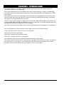
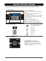
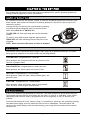
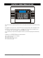
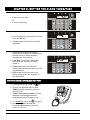
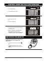
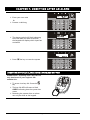
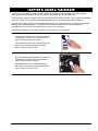
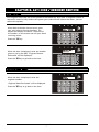
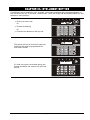
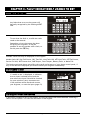
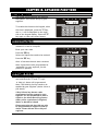
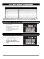
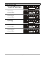
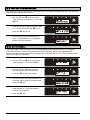
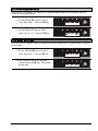
User Manual EN50131-3 : 2009 EN50131-6 : 2008 EN50131-5-3 : 2005 Security Grade 2 Environmental Class II RINS1346-3 Default codes: User code:1234 Master Manager Code: 2222 CONTENTS CHAPTER 1: INTRODUCTION........................................................................................... 4 CHAPTER 2: KEYPADS / READERS ................................................................................ 5 CHAPTER 3: THE KEY-FOB .............................................................................................. 6 3.1 LOCKING THE KEY-FOB .............................................................................................................. 6 3.2 BUTTONS................................................................................................................................... 6 3.3 QUICK SETTING ......................................................................................................................... 6 CHAPTER 4: USING PREDICTIVE TEXT .......................................................................... 7 CHAPTER 5: SETTING THE ALARM (CODE/TAG) .......................................................... 8 CHAPTER 6: UNSETTING THE ALARM (CODE/TAG) ..................................................... 9 CHAPTER 7: UNSETTING AFTER AN ALARM .............................................................. 10 CHAPTER 8: USING A TAG READER ............................................................................ 11 CHAPTER 9: ANTI CODE / ENGINEER RESTORE ........................................................ 12 9.1 ANTI-CODE .............................................................................................................................. 12 9.2 ENGINEER RESET .................................................................................................................... 12 CHAPTER 10: INTELLIGENT SETTING .......................................................................... 13 CHAPTER 11: FAULT INDICATIONS / UNABLE TO SET .............................................. 14 11.1 FAULT INDICATIONS ............................................................................................................... 14 11.2 UNABLE TO SET ..................................................................................................................... 14 11.3 KEY-FOB FAULT INDICATIONS ................................................................................................ 14 CHAPTER 12: ADVANCED FUNCTIONS ........................................................................ 15 12.1 CHIME FEATURE .................................................................................................................... 15 12.2 OMITTING INPUTS................................................................................................................... 15 12.3 KEYPAD HOLD UP.................................................................................................................. 15 CHAPTER 13: MASTER MANAGER MENU .................................................................... 16 13.1 ENTERING THE MASTER MANAGER MENU............................................................................... 16 13.2 EXITING THE MASTER MANAGER MENU .................................................................................. 16 13.3 SET DATE AND TIME .............................................................................................................. 17 13.4 CHANGE CODES (ADDING CODES, TAGS AND KEY-FOBS) ........................................................ 18 13.5 REVIEW LOGS........................................................................................................................ 20 13.6 PHONEBOOK.......................................................................................................................... 20 13.7 WALK TEST ........................................................................................................................... 21 13.8 SIREN TEST ........................................................................................................................... 21 13.9 TEST CHC COMMUNICATIONS ................................................................................................ 22 13.10 DIAL OUT MENU .................................................................................................................. 22 13.11 ALLOW ENGINEER MENU ..................................................................................................... 23 13.12 ENTER ANTI-CODE............................................................................................................... 23 CHAPTER 14: DISCLAIMER ............................................................................................ 24 CHAPTER 15: ENGINEER CONTACTS AND TABLES................................................... 25 15.1 ENGINEER INFORMATION ........................................................................................................ 25 15.2 CERTIFICATION ...................................................................................................................... 25 15.3 INPUT CONTACT TABLE.......................................................................................................... 26 CHAPTER 1: INTRODUCTION Your control panel is a two-way wireless security alarm that boasts 32 wireless inputs, 32 wireless key-fobs and 2 wireless bells. The wireless devices that you can add to your control panel comprise a range of wireless PIRs, universal transmitters and a shock sensors; the control panel also allows the addition of 2 DEOL wired inputs. The system also has 80 user codes/tags, 32 of which may be programmed as a wireless key-fob that can either set/unset the system or control an output (by latching the output or activating the output for a programmable time period). There are also 3 wired outputs on-board the control panel; PGM, STB and BELL, all of which are programmable (BELL and STB are defaulted to work on a bell box). An output expander may also be connected allowing an additional 16 wired outputs. Up to four set points can be used on the control panel (maximum of 4 keypads or 3 tag readers). Your control panel is a level set system which may be set up in the following way: A user can choose which level set to arm, for example: Level Set A: Full set of the house Level Set B: Upstairs set. Downstairs unset. Level Set C: Garage set. Rest of house unset. Your engineer will be able to design the system according to your needs. The control panel can be set up to communicate to an alarm receiving centre which can monitor all activations of your property. You can also have SMS texts sent to your phone when alarm activation has occurred. Please ask your engineer for more information. Page: 4 CHAPTER 2: KEYPADS / READERS There are three different devices that may be used in the process of setting/unsetting the alarm system; these are the main keypad, the external tag reader and the internal tag reader. Control Panel Keypad a = Exit manager menu. b = Moves backwards to the previous menu item. c = Enables chime and displays additional information in the log. D = Moves forward in the log, scrolls between options and enters the master manager menu. f p = Not used. [ ] = Directional buttons. I = Selects items and enters menus. A = Cancels items, resets the panel and moves to next item in master manager menu. The Internal Tag Reader Tag Area (Where you present your tag to arm/Unset) Alert LED Alarm LED Tamper LED Fault LED Unset LED The External Tag Reader LEFT GREEN LED: Status indicator (extinguishes after a couple of seconds) RED LED: This can be programmed by your engineer to illuminate when the alarm has activated for example. Page: 5 CHAPTER 3: THE KEY-FOB The wireless key-fob has 4 buttons that may be programmed for specific purposes (please see Change codes on page 18 for more information). 3.1 Locking the Key-fob All 4 buttons on the key-fob may be ‘locked’ so that any accidental presses will not affect your alarm system (this protects the buttons from being pressed if a key-fob is next to keys etc in someone’s pocket) Locking the keys on the key-fob is performed by pressing any buttons that are diagonal with one another at the same time (LOCK & II or UNLOCK & I). The RED LED will flash indicating that the fob has been locked. To unlock, press both buttons together again and the GREEN LED will flash indicating that the key-fob is now unlocked. NOTE: When locked the LED status will also be disabled 3.2 Buttons The buttons can be customised (see Change Codes, page 18) to operate as desired. The table below gives an example of how each button may be programmed. LOCK BUTTON = Programmed for ‘Set Area’ When pressed, the chosen area will be set (chosen in the function ‘Change Codes’). UNLOCK BUTTON = Programmed for ‘Unset Any Area’. When pressed, the alarm system will unset (if set). I BUTTON = Programmed for ‘Latch Output’ When pressed, a gate will open. When pressed again, the gate will close. II BUTTON = Programmed for ‘Timed Output’ When pressed, a door will unlock, after a programmed time, the door will lock again automatically. 3.3 Quick Setting If one of the buttons is programmed as ‘Set Area’, the alarm system can be set by the key-fob. The keypad will then start to count down the exit time, or wait for a ‘final door’ to be closed (depending what the exit mode is programmed as by the engineer) or the PTS button to be pressed. Once the alarm panel is in this ‘setting’ stage, it is possible to ‘quick set’ the system by pressing the same button again; this will reduce the time to set to immediate. The alarm panel will revert to the normal display with the time showing, but a beep will be heard once the system has been set. Page: 6 CHAPTER 4: USING PREDICTIVE TEXT The control panel incorporates predictive text, so the system will predict the word that is being spelt. For example, if you type ‘John’, press the 5 key once and the name ‘Julia’ will appear. Press the D key to move the cursor over the ‘u’, and press the 6 key 3 times to change it to an ‘o’. The name ‘John’ will now appear. Press the I key to accept. If the word that you require does not appear in the list, just continue typing the word letter by letter. In addition, the a b c D keys are used as follows: a = make the character into a capital b= move cursor left c= clears cursor / adds a space D = moves cursor right Page: 7 CHAPTER 5: SETTING THE ALARM (CODE/TAG) Enter your user code Or Present a valid tag Enter the level set you wish to set, and press the I key ‘Please wait arming wireless’ will be displayed There are three different setting methods your installer will instruct you through which of these has been designed into your system. Final Door: Leave the building and make sure the exit door is closed properly Timed: Make sure you leave the building before the timer shown on the keypad expires Push to set: Press the push to set button installed by your engineer to arm the system SETTING USING A WIRELESS KEY-FOB To set via a key-fob. Press the key The key-fob LED will start to flash GREEN indicating that the system is starting to set ‘Please wait arming wireless’ will be displayed on the keypad and the programmed area will begin to set. To ‘quick set’, press the key again. Once set, the key-fob LED will illuminate RED indicating that the system is now set Page: 8 CHAPTER 6: UNSETTING THE ALARM (CODE/TAG) Enter the building The Entry time will start Enter your user code Or Present a valid tag The level set that the code is assigned to will be Unset. Note: If ‘flexi-set’ is disabled (see page 18) then the system will automatically Unset that level set once a valid user code or tag is presented. UNSETTING USING A WIRELESS KEY-FOB PLEASE NOTE: Unsetting with a key-fob will only be allowed if your engineer has enabled this. To unset via a key-fob. Press the key The key-fob LED will start to flash GREEN indicating that the system has unset. Page: 9 CHAPTER 7: UNSETTING AFTER AN ALARM Enter your user code Or Present a valid tag The alarm symbol will flash indicating there has been an alarm activation, the keypad will display which input has activated. Press A the key to reset the system UNSETTING AFTER AN ALARM USING A WIRELESS KEY-FOB PLEASE NOTE: Unsetting with a key-fob will only be allowed if your engineer has enabled this. To unset via a key-fob. Press the key The key-fob LED will start to flash GREEN indicating that the system has unset. Resetting the system after an alarm can only be done at the keypad. Page: 10 CHAPTER 8: USING A TAG READER If you have a tag reader installed, then it will be possible to set and unset the alarm system using a tag (the same tags can also be used to arm/Unset via the keypad prox). There are two types of readers that can be used with the Alarm System - the Internal Tag Reader (used for indoors only) and the External tag reader (used for both indoors and outdoors). Tags for the readers need to be programmed through the ‘Change Codes’ function in the Master Manager Menu (see page 18). The internal and external readers can be both assigned to individual level sets, this will need to be set up by your engineer. Enabling the readers to the alarm system will be done by your engineer. To set/unset the system using the Internal Tag Reader, present a pre-programmed tag to the tag symbol as shown. The system will then set depending on the type of exit mode programmed (Final door, Timed or Push to set) To set/unset the system using the external Tag Reader, present a pre-programmed tag to the centre of the prox. The system will then arm depending on the type of exit mode programmed (Final door, Timed or Push to set) Page: 11 CHAPTER 9: ANTI CODE / ENGINEER RESTORE 9.1 Anti-Code Your engineer may have set up the system so that either an ‘anti code’ or engineer restore is required in order to fully restore the system (your code will still silence the alarm, just not restore the system). After alarm activation has occurred, enter your user code to silence the alarm. The keypad will display as follows. Take note of the number, on the screen and call your alarm receiving centre. Press the I key When the time is displayed, enter the number given to you by the ARC. ‘Engineer Restore Performed’ will be displayed. Press the A key to go back to the time. 9.2 Engineer Reset When the time is displayed, enter the engineer number. ‘Engineer Reset Performed’ will be displayed. Press the A key to go back to the time. Page: 12 CHAPTER 10: INTELLIGENT SETTING If intelligent arm is enabled by your engineer, the system automatically recognises whether to full arm (Level Set A), or part arm. (Level Set B). ‘Flexi’Arm (Page 18) should be disabled for this feature to work properly. Enter your user code Or Present a valid tag Or Press the set button on the key-fob The system will set in level set B (the user code/tag/fob must be programmed for level sets A and B). Quick Arming... If a final exit input is activated during the setting procedure the system will quick set area A. Page: 13 CHAPTER 11: FAULT INDICATIONS / UNABLE TO SET 11.1 Fault Indications Any faults that occur on the system will be easily recognised by the flashing ALERT LED. To see what the fault is, a valid user code needs to be entered. Depending on how the system has been set up by your engineer, it may be possible to arm the system with a fault, to do this press the I key. Possible faults that may be displayed on the keypad: Modem fault 100, Digi Fail Comm, CHC Test Fail, Line Fault 100, ATE Line Fault, ATE Fail Comm, Device Fail ###, 485/Comms Lost, SAB Tamper, Case Tamper, Battery Fault, or Mains Fail. The faults mentioned above may affect the overall performance of your alarm control panel, if any of the above are displayed you should contact your engineer immediately. 11.2 Unable to Set If ‘unable to set’ is displayed, it indicates that an input is already active and the area where the input is should be checked for open windows, pets, movement etc. If the problem cannot be solved contact your engineer, or omit the input (page 15) 11.3 Key-fob Fault Indications If the panel is unable to set for any reason, the key-fob status LED flashes ORANGE indicating a fault is on the system. The fault will be shown on the keypad. Page: 14 CHAPTER 12: ADVANCED FUNCTIONS 12.1 Chime Feature The chime can be used for any input on the system. This can be set up by your engineer. To enable the chime on the keypad, when the time is displayed, press the c key, and a ‘c’ will be displayed on the right side of the keypad display. Press the c key again to clear the chime feature. 12.2 Omitting Inputs On occasion, a detector may need to be isolated if a room is occupied. Enter your user code Press the I key Select the inputs that need to be omitted Press the A key After 10 seconds the exit time continues Note: Inputs have to be programmed as ‘omittable’ by your engineer for this feature to operate. 12.3 Keypad Hold Up If an emergency alarm is needed, press and hold both the 1 and 7 keys. A ‘hold up’ alarm will be generated. Note: The Hold Up facility needs to be enabled by your engineer (either silent or full alarm) 2-Key HU and any duress codes programmed on the system by your engineer are not permitted to send a signal to the Alarm Receiving Centre under police regulations in England, Wales or Northern Ireland Please note that the key-fob can also be programmed to support a hold up alarm. Please discuss this with your engineer. Page: 15 CHAPTER 13: MASTER MANAGER MENU The Master Manager Menu has the following functions: Function Set Date and Time Change Codes Review Logs Phone Book Walk Test Siren Test Test CHC Communications Dial Out Menu Allow Engineer Menu Exit Manager Mode Description Programs the date and time Adds/Edits/Deletes user/master codes and tags Displays all information of the control panel Adds/Edits/Deletes SMS phone numbers Walk tests each input Performs a test on all bell boxes connected Tests a call to the SMS station Dials to a PC for Uploading/Downloading Enables or Disables engineer access Exits the master manager menu. The Master Manager has access to all the options above. A ‘user code’ has access to the ‘User Menu’ which includes the functions: ‘Change Code’, ‘Review Logs’, ‘Allow Engineer Menu’, and ‘Exit User Menu’ . 13.1 Entering the Master Manager Menu Press the D key Enter the master manager code (or user code/tag) Use the b and A keys to scroll through the different functions mentioned above. 13.2 Exiting the Master Manager Menu Use the b and A keys to scroll through until ‘Exit Manager Mode’ is displayed. Press the I key. OR, when a main menu item is displayed (capital letters) press the a key. Page: 16 13.3 Set Date and Time Use the b and A keys to scroll to ‘Set Date & Time’. Press the I key. Enter the Year Press the I key Enter the Month Press the I key Enter the Day Press the I key Enter the Hours Press the I key Enter the Minutes Press the I key Page: 17 13.4 Change Codes (Adding codes, tags and key-fobs) The ‘Change Codes’ function allows adding, editing and deleting of user codes and the edit of the master manager code. Tags can also be programmed here for any user code, as well as wireless key-fobs (which are each assigned to a user) The control panel can have up to 80 user codes/tags (up to 32 users can be assigned to wireless key-fobs) Button Actions: Each wireless key-fob has 4 buttons that can be programmed for any of the functions below: No Action = Disables the button Show Status = If the key-fob is learnt the LED will flicker when asked for the status. Set Area = Sets the chosen area Unset Any Area = Unsets any area on the system Latch Output = Enables an output that your engineer may have programmed Timed Output = Enables an output for a period of time that your engineer may have programmed Flexi-Set: Flexi-set allows you to choose which level/area to set if a user code is assigned to one or more levels/areas. If this function is disabled, when a user code is entered, the system will automatically set the levels/areas that the code is assigned to. Use the b and A keys to scroll to ‘Change Codes’. Press the I key. To edit user codes, press the I key. Enter the user number to be edited Press the I key Enter the new code / present a tag / press a key-fob button Once ‘asterisks’ appear, the tag or key-fob will be assigned to this user. Press the I key Programming Wireless Key-fobs If a key-fob is to be programmed, enter the user name, and then select the different buttons to program using the b and D keys. Press the I key Programming Wireless Key-fobs Select the appropriate action for the button using the b and D keys. Press the I key Page: 18 Choose the type, either ‘user’ or ‘manager’ using the d key Press the I key (This screen will not be displayed if you have programmed a wireless key-fob) Enter the arm modes/partitions that the user will be assigned to. Press the I key Choose the Setting option for the user code: Unset/Set, Unset, Set, using the D key. Press the I key. (This screen will not be displayed if you have programmed a wireless key-fob) Chooses whether Flexi-Set is to be enabled/disabled using the D key. Press the I key (This screen will not be displayed if you have programmed a wireless key-fob) Enter the user name (for help on predictive text please see page 7) Press the I key. To edit the Master Manager Code, press the I key. Enter the new code / present a tag / press a key-fob button Press the I key Repeat the same procedure as above. Page: 19 13.5 Review Logs The ‘Review Logs’ function monitors all operational information of the alarm system, such as setting/unsetting information and alarm activations etc. Use the b and A keys to scroll to ‘Review Logs’. Press the I key Press the I key The most recent event will be displayed, press the b and D keys to scroll backwards and forwards through the log. Press the c key to show more information (such as which input activated, or which user set the system etc) 13.6 Phonebook If SMS texting is programmed, there will be up to 4 mobile numbers also programmed which may be changed in this function. If any numbers are added, you will need to perform a CHC test to activate each call (see page 22). Use the b and A keys to scroll to ‘Phonebook’. Press the I key Use the b and D keys to scroll through the different telephone numbers. Enter the mobile number. Press the I key. Page: 20 13.7 Walk Test The ‘Walk Test’ function allows the testing of all programmed inputs on the alarm system. Use the b and A keys to scroll to ‘Walk Test’. Press the I key Select which level set to walk test. Press the I key to walk test all inputs or press the A key to walk test an input individually. Walk testing all inputs Walk test the mentioned inputs on the display. After all inputs have been walk test successfully ‘walk test completed’ will be displayed. Walk testing individual inputs Use the b and D keys to scroll through the different inputs and press the I key to walk test that input 13.8 Siren Test This function is used to test the siren and strobe outputs Use the b and A keys to scroll to ‘Siren Test’. Press the I key This tests both the siren and strobe outputs. Press the I key Page: 21 13.9 Test CHC Communications This function is used in conjunction with SMS texts. It is used to communicate with the SMS Host computer (the mobile phone server). Use the b and A keys to scroll to ‘Test CHC Communications’. Press the I key If you are using a PABX line (that needs a ‘9’ to dial out) press the I key or press the A key if not. The control panel will then call the CHC. If ‘Failed CHC test’ is displayed, please call your engineer. 13.10 Dial Out Menu The control panel may be dialled into, and programming information kept on a PC using the InSite UDL software. This function allows the control panel to dial a Pre-programmed PC telephone number (programmed by your engineer) to directly dial to a PC. This is usually used when your engineer requests it. Use the b and A keys to scroll to ‘Dial Out Menu’. Press the I key Use the b and D keys to scroll through the different PC numbers, press the I to dial that number Use the b and D keys to select the operation that needs to be performed. Press the I key. The control panel will dial the programmed PC. If this fails please contact your engineer. Press the A key. Page: 22 13.11 Allow Engineer Menu If this function is enabled, the engineer will require authorisation from you before they can access the engineering menu. Use the b and A keys to scroll to ‘Allow Engr Menu’. Press the I key Use the b and D keys to select either ‘yes’ or ‘no’. Press the I key. 13.12 Enter Anti-Code If an anti-code or engineer code is required to reset the system after an alarm event, it may be entered here. Use the b and A keys to scroll to ‘Enter Anti-Code’. Press the I key Enter the anti-code or the engineer code and Press the I key. The system will be reset. Page: 23 CHAPTER 14: DISCLAIMER The control panel includes the facility to send electronic signals to an Alarm Receiving Centre (ARC), and also to send SMS text messages to mobile telephones. Alarm, etc. signals may be transmitted via a PSTN link, using a variety of formats, to suitable receiving equipment located at the premises of an independently operated Alarm Receiving Centre. Provision is also made for the use of third-party device to transmit signals to an Alarm Receiving Centre by means of the PSTN, GSM, IP or other network. The SMS facility uses a PSTN connection to a special SMS Centre, where the information is transferred to the GSM network for delivery to the client’s designated mobile telephone(s). The SMSC services are provided by GSM network operators or other reputable companies, whose operation is outside the manufactures of the control panel, have an embedded premium rate telephone number that is used to contact a Host computer prior to commissioning, in order to download the SMSC details and appropriate call routing authorisation. The control panel will continue to contact this CHC at regular intervals, to verify the operation and update and confirm the routing information and authorisation as appropriate. The charge for this service is raised by the use of the “premium rate” telephone number. Please check with your installer for exact charges. Whilst we will use our best endeavours to resolve any issues relating to these uses of equipment made by us are in no way responsible for the operation of the PSTN or other transmission media, the Alarm Receiving Centre or the SMSC - or for the endto-end security and delivery Page: 24 CHAPTER 15: ENGINEER CONTACTS AND TABLES 15.1 Engineer Information Alarm Company Date of Installation Site Reference Engineer Name Engineer Contact Number Installed to Grade Environmental Class (see below) 2 Your panel is suitable for use in installations designed to meet the European requirements of Security Grade 2, Environmental Class 2. When all parts are working normally, this equipment in combination with the PSTN and suitable ARC equipment will meet the requirements of ATS2. External arm/disarm readers meet the requirements of environmental class 4. Your panel is designed to automatically inhibit certain functionality. The factory default settings are shown below: Intruder Alarm Signal Tamper Alarm Signal Keypad After 3* unconfirmed alarms in the same area or 1 confirmed alarm. After 3* unconfirmed alarms in the same area or 1 confirmed alarm. After 30 key presses without entering a valid code, keys are disabled for 90 seconds. After reinstatement, this will be repeated after each 7 key presses until a valid code is entered. Tag Reader (or Tag at a keypad) After 6 presentations of an invalid tag, the reader will be disabled for 90 seconds. After reinstatement, this will be repeated for each invalid tag until a valid tag is used. * This figure is programmable by the Engineer. Number of Code Differs: tag hex code. 15.2 Certification All Wireless devices comply with the following EU requirements: EMC Directive 2004/108/EC Low Voltage Directive 2006/95/EC R&TTE Directive 1999/5/EC And meet the following standards where relevant: EN 61000-6-3:2001 EMC. Generic emission standard. Residential, commercial and light industry EN 50130-4:1996 +A1 +A2 Immunity requirements for components of fire, intruder and social alarm systems EN 60950-1:2006 Information technology equipment. Safety. General requirements EN 50131-5-3:2005 Grade 2. Interconnections for equipment using radio frequency techniques ETSI EN 301489-3:2000 EMC. Radio equipment. Part 3: Short range devices (SRD) 9kHz to 40 GHz ETSI EN 300 220 EMC. Receiver Class 1, Environmental Category 1 CEPT/ERC Recommendation 70-03 Annex 1 Compliant operation is only guaranteed when installed and operated according to the relevant installation and user manuals. Page: 25 15.3 Input Contact Table Input No 1 2 3 4 5 6 7 8 9 10 11 12 13 14 15 16 17 18 19 20 21 22 23 24 25 26 27 28 29 30 31 32 33 Input Name Input Areas 34 Page: 26 Description