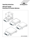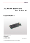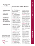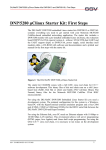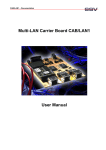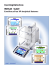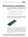
1
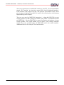
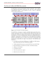
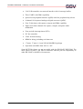
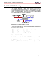
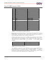
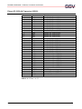
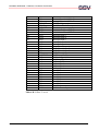
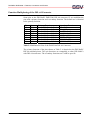
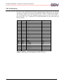
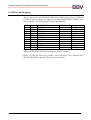
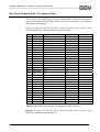
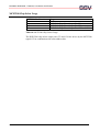
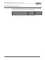
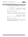
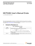
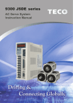
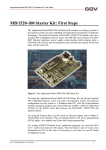
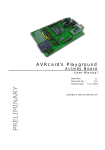
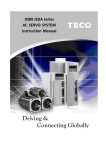
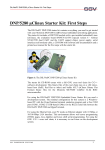
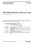
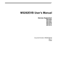
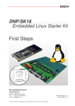
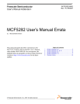
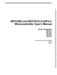
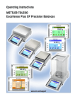
DIL/NetPC DNP/5280 – Features, Connectors and Pinouts
DNP/5280 Revision 1.21 – User Information
The DIL/NetPC DNP/5280 provides a very compact ColdFire-based low
power embedded controller (Motorola 32-bit MCF5280) with TCP/IP stack
and Web server for high-speed embedded networking applications. The main
features are:
•
ColdFire Microcontroller MCF5280 with 66 MHz Clock Speed
•
128 Mbit (16 Mbytes) SDRAM MT48LC4M32B2 with 32-bit Data Bus
•
64 Mbit (8 Mbytes) Flash Am29LV640 with 16-bit Data Bus
•
10/100 Mbps Ethernet PHY RTL8201 (25 MHz Clock Source)
The DIL/NetPC offers the footprint of a standard 64-pin DIL socket with 2.54mm
centers and all the hardware and software features necessary to add high-speed
networking capabilities to any product design. The DIL/NetPC is developed
specifically for products that need to be connected to 10 or 100 Mbps Ethernetbased TCP/IP networks with minimum development costs.
Figure 1: The DIL/NetPC DNP/5280 with a ColdFire MCF5280 Microcontroller
The DIL/NetPC DNP/5280 is a ready-to-run full programmable 32-bit embedded
networking system. The use of the DNP/5280 will allow you to realize substantial
time and costs savings over other chip-based approaches. Currently, there is no
other 10/100 Mbps Ethernet- and TCP/IP-based embedded networking solution
with more development time savings on the market. There is also no faster Timeto-Market for your product with lower costs if 32-bit-based 10/100 Mbps
Ethernet, full TCP/IP and a embedded Web server or other TCP/IP-based server
software is required.
To interface the DNP/5280 with existing devices and equipment, the DNP/5280
SSV EMBEDDED SYSTEMS
1
DIL/NetPC DNP/5280 – Features, Connectors and Pinouts
offers two asynchronous serial RS232C interfaces with TTL levels and handshake
signals, I2C interchip bus interface, queued SPI (Serial Peripheral Interface),
CAN interface with support for the CAN protocol specification 2.0B, 20-bit
general purpose high-speed parallel I/Os and a 8-bit extension bus with interrupt
inputs and chip select outputs.
There are two ways for DNP/5280 integration: 1. Adapt the DNP/5280 to your
existing product. Use the existing I/Os within your product to communicate with
the DNP/5280. 2. Use the DNP/5280 to control and monitor the hardware of your
existing product. This might enable you to replace your existing controller
entirely. In a new product design, the DNP/5280 can be the main controller.
Additional I/Os are driven by the 8-bit extension bus.
SSV EMBEDDED SYSTEMS
2
DIL/NetPC DNP/5280 – Features, Connectors and Pinouts
The Motorola ColdFire MCF5280 Microcontroller
The MCF5282 is the first microcontroller based on Motorola's 32-bit ColdFire
core integrated with Ethernet, Flash and CAN. This device offers advanced
communications features, a rich peripheral set and a variety of supporting
software and development tools.
Figure 2: MCF5280/MCF5282 Block Diagram
The MCF5282 is designed to simplify embedded Ethernet-networked microcontroller applications. With its integrated 10/100 Mbps Ethernet MAC and
network-ready applications software, the MCF5282 can bring standards-based
networking to a variety of traditional MCU applications including food service
equipment, security systems, vending machines, exercise equipment and industrial
controllers. Applications in all of these areas will benefit from networking
functions such as Web-based user interfaces, network time synchronization, and
router/gateway functionality for legacy serial protocols. The MCF5282 main
features are:
•
V2 ColdFire core delivering 54 (Dhrystone 2.1) MIPS at 66 MHz running
from internal Flash (max from Cache/RAM 63 MIPS)
•
512KB embedded Flash memory (only the MCF5282, not the MCF5280)
•
Enhanced Multiply-Accumulate Unit (eMAC) for DSP functionality
•
64 Kbytes of static RAM
•
10/100 Ethernet MAC
•
Cache for external access support
•
Address decode and chip selects
SSV EMBEDDED SYSTEMS
3
DIL/NetPC DNP/5280 – Features, Connectors and Pinouts
•
CAN 2.0B controller area network interface with 16 message buffers
•
Three UARTs with DMA capability
•
Queued serial peripheral interface (QSPI) with four peripheral chip selects
•
8-channel 10-bit queued analog-to-digital converter (QADC)
•
Four 32-bit timers with capture, compare and DMA capability
•
Eight 16-bit timer channels for capture, compare, and pulse width
modulation
•
Four periodic interrupt timers (PITs)
•
I2C bus controller
•
JTAG for board testing
•
BDM for debug, including real-time trace
•
17 mm x 17 mm x 1.6 mm 256-ball MAPBGA package
•
Operation at 66 MHz from -40C to +85C
Some MCF528x feature are not accessible with the DIL/NetPC DNP/5280. The
main reason for that is the DIL-64 connector and the pin-out compatibility to
other DIL/NetPCs with DIL-64 connectors.
SSV EMBEDDED SYSTEMS
4
DIL/NetPC DNP/5280 – Features, Connectors and Pinouts
The DIL/NetPC DNP/5280 Block Diagram
The DIL/NetPC DNP/5280 is build around Motorola's 32-bit ColdFire
MCF5280/MCF5282 microcontroller unit (MCU) running with 66 MHz. The
external main components around the ColdFire are one Flash memory chip with 8
Mbytes, one 16-MByte SDRAM memory chip, and one 10/100 Mbps Ethernet
PHY (the Ethernet MAC is a part of the ColdFire MCU).
Figure 3: DIL/NetPC DNP/5280 Block Diagram
The DIL/NetPC DNP/5280 LAN interface is equipped with four small on-board
LEDs. Table 1 offers a overview.
Name
LED0
LED1
LED2
LED3
Function
Link
Duplex
10Act
100Act
Ethernet Cable Connection available
Duplex Mode
10 Mbps LAN Traffic
100 Mbps LAN Traffic
Table 1: DNP/5280 LAN LEDs
The 66 MHz clock speed of the DIL/NetPC DNP/5280 comes from a 8 MHz
clock source.
The DNP/5280 offers only two connectors: J1 (BDM Interface) and J2 (64-pin
DIL Connector). Table 2 and Table 4 of this document show the pinout.
SSV EMBEDDED SYSTEMS
5
DIL/NetPC DNP/5280 – Features, Connectors and Pinouts
Pinout J1: BDM Connector (J0501)
Pin
1
2
3
4
5
6
7
8
9
10
11
12
13
14
15
16
17
18
19
20
Name
VIO (3.3 VDC I/O Voltage)
GND
TA#
BKPT#
Reset#
DSCLK#
DSI#
TCLK
PST3
DS0
PST2
DDATA3
PST1
DDATA2
PST0
DDATA1
PSTCLK
DDATA0
GND
RCM
Remarks
BDM Function
BDM Function
BDM Function
BDM Function
BDM Function
BDM Function
BDM Function
BDM Function
BDM Function
BDM Function
BDM Function
BDM Function
BDM Function
BDM Function
BDM Function
BDM Function
GPTB3
Table 2: J1 Pinout (DNP/5280 BDM Connector)
Please note: Pin 20 (RCM = Remote Console Mode) of connector J1 is a jumper
position point. The DNP/5280 allows you to connect this pin with the help of a
small 2 mm jumper bridge to pin 19 (GND) of connector J1.
RCM is direct connected to pin T12 (GPTB3) of the Motorola 32-bit ColdFire
MCF5280/MCF5282 microcontroller. There is also a 4700 Ohms resistor to 3.3
VDC on-board for pulling GPTB3 to Vcc (GPTB3 = 1) if no jumper bridge
available.
Pin 19 – Pin 20
Jumper not available
Jumper available
Status
GPTB3 = 1 (High)
GPTB3 = 0 (Low)
Table 3: The RCM Jumper Modes
The DNP/5280 default boot loader and ROM monitor program dBUG checks
RCM at power-up. If no jumper bridge is available (GPTB3 = 1), dBUG is
running the uClinux image from Flash memory. If dBUG detects a jumper bridge
from pin 19 to pin 20, this program enters a command mode.
SSV EMBEDDED SYSTEMS
6
DIL/NetPC DNP/5280 – Features, Connectors and Pinouts
Pinout J2: DIL-64 Connector (J0901)
Pin
1
2
3
4
5
6
7
8
9
10
11
12
13
14
15
16
17
18
19
20
21
22
23
24
25
26
27
28
29
30
31
32
Name
PA0
PA1
PA2
PA3
PA4
PA5
PA6
PA7
PB0
PB1
PB2
PB3
PB4
PB5
PB6
PB7
PC0
PC1
PC2
PC3
RXD1
TXD1
CTS1
RTS1
DCD1
DSR1
DTR1
RI1
RESIN
TX+
TXGND
Function
Parallel I/O, Port A, Bit 0
Parallel I/O, Port A, Bit 1
Parallel I/O, Port A, Bit 2
Parallel I/O, Port A, Bit 3
Parallel I/O, Port A, Bit 4
Parallel I/O, Port A, Bit 5
Parallel I/O, Port A, Bit 6
Parallel I/O, Port A, Bit 7
Parallel I/O, Port B, Bit 0
Parallel I/O, Port B, Bit 1
Parallel I/O, Port B, Bit 2
Parallel I/O, Port B, Bit 3
Parallel I/O, Port B, Bit 4
Parallel I/O, Port B, Bit 5
Parallel I/O, Port B, Bit 6
Parallel I/O, Port B, Bit 7
Parallel I/O, Port C, Bit 0
Parallel I/O, Port C, Bit 1
Parallel I/O, Port C, Bit 2
Parallel I/O, Port C, Bit 3
COM1 Serial Port, RXD Pin
COM1 Serial Port, TXD Pin
COM1 Serial Port, CTS Pin
COM1 Serial Port, RTS Pin
COM1 Serial Port, DCD Pin
COM1 Serial Port, DSR Pin
COM1 Serial Port, DTR Pin
COM1 Serial Port, RI Pin
RESET Input
10/100 Mbps LAN, TX+ Pin
10/100 Mbps LAN, TX- Pin
Ground
Table 4.A: J2 Pins 1 to 32
SSV EMBEDDED SYSTEMS
7
DIL/NetPC DNP/5280 – Features, Connectors and Pinouts
Pin
33
34
35
36
37
38
39
40
41
42
43
44
45
46
47
48
49
50
51
52
53
54
55
56
57
58
59
60
61
62
63
64
Name
RX+
RXRESOUT
VBAT
CLKOUT
TXD2
RXD2
INT5
INT4
INT3
INT2
INT1
CS4
CS3
CS2
CS1
IOCHRDY
IOR
IOW
SA3
SA2
SA1
SA0
SD7
SD6
SD5
SD4
SD3
SD2
SD1
SD0
VCC
Function
10/100 Mbps LAN, RX+ Pin
10/100 Mbps LAN, RX- Pin
RESET Output
Real-Time Clock Battery
Clock Output
COM2 Serial Port, TXD Pin
COM2 Serial Port, RXD Pin
Interrupt Input 5
Interrupt Input 4
Interrupt Input 3
Interrupt Input 2
Interrupt Input 1
Chip Select Output 4
Chip Select Output 3
Chip Select Output 2
Chip Select Output 1
I/O Channel Ready
I/O Read Signal
I/O Write Signal
Address Bit 3
Address Bit 2
Address Bit 1
Address Bit 0
Data Bit 7
Data Bit 6
Data Bit 5
Data Bit 4
Data Bit 3
Data Bit 2
Data Bit 1
Data Bit 0
3.3 Volt Power Input
Table 4.B: J2 Pins 33 to 64
SSV EMBEDDED SYSTEMS
8
DIL/NetPC DNP/5280 – Features, Connectors and Pinouts
Function Multiplexing of the DIL-64 Connector
Some pins at the DIL/NetPC DNP/5280 DIL-64 connector J2 are multifunction
pins with a primary function and a secondary function. The default use is identical
to the primary function.
Pin
13
14
15
16
17
18
19
20
Name
PB4
PB5
PB6
PB7
PC0
PC1
PC2
PC3
Primary Function
Parallel I/O, Port B, Bit 4
Parallel I/O, Port B, Bit 5
Parallel I/O, Port B, Bit 6
Parallel I/O, Port B, Bit 7
Parallel I/O, Port C, Bit 0
Parallel I/O, Port C, Bit 1
Parallel I/O, Port C, Bit 2
Parallel I/O, Port C, Bit 3
Secondary Function
SCL (I2C)
SDA (I2C)
CANTX (CAN)
CANRX (CAN)
QSPIDO (SPI)
QSPIDI (SPI)
QSPICLK (SPI)
QSPICS0 (SPI)
Table 5: Multifunction Pins of the DNP/5280 DIL-64 Connector
The primary function of the pins shown at Table 5 is identical to the DIL/NetPC
DIL-64 standard pinout. This pin functions are compatible to other DIL/NetPCs
with DIL-64 connectors. The secondary functions are ColdFire-specific.
SSV EMBEDDED SYSTEMS
9
DIL/NetPC DNP/5280 – Features, Connectors and Pinouts
PIO Pin Mapping
The bits of the DNP/5280 20-bit PIO (Parallel Input Output Port) are directly
connected to signals of the Motorola MCF5280 ColdFire 32-bit microcontroller.
The following table shows this mapping. Please see also the MCF5282 ColdFire
Microcontroller User’s Manual R.0.1 (MCF5282UM/D) for the MCF5280 pin
function details.
Pin
1
2
3
4
5
6
7
8
9
10
11
12
13
14
15
16
17
18
19
20
Name
PA0
PA1
PA2
PA3
PA4
PA5
PA6
PA7
PB0
PB1
PB2
PB3
PB4
PB5
PB6
PB7
PC0
PC1
PC2
PC3
MCF5280 Pin Function
AN52
AN53
AN55
AN56
AN0
AN1
AN2
AN3
GPTA0
GPTA1
GPTA2
GPTA3
SCL
SDA
CANTX
CANRX
QSPIDO
QSPIDI
QSPICLK
QSPICS0
MCF5280 Pin
R4
T4
P3
R3
T3
R2
T2
R1
N13
P13
R13
T13
E15
E14
E13
D16
F13
E16
F14
F15
Table 6: DNP/5280 PIO Pin Mapping to MCF5280 Pins
SSV EMBEDDED SYSTEMS
10
DIL/NetPC DNP/5280 – Features, Connectors and Pinouts
COM Port Pin Mapping
The 10 pins of the two DIL/NetPC DNP/5280 UARTs (Serial Ports COM1 and
COM2) are direct connected to signals of the Motorola MCF5280 ColdFire 32-bit
microcontroller. The following table shows this mapping.
Pin
21
22
23
24
25
26
27
28
Name
RXD1
TXD1
CTS1
RTS1
DCD1
DSR1
DTR1
RI1
MCF5280 Pin Funktion
URXD0
UTXD0
DTOUT0
DTOUT1
DTOUT2
DTIN2
DTOUT3
DTIN3
MCF5280 Pin
N6
T7
J13
J15
K13
K14
K15
K16
Source
UART
UART
UART
UART
GPIO
GPIO
GPIO
GPIO
38
39
TXD2
RXD2
UTXD1
URXD1
P7
R7
UART
UART
Table 7: DNP/5280 COM Port Pin Mapping to MCF5280 Pins
Please see also the MCF5282 ColdFire Microcontroller User’s Manual R.0.1
(MCF5282UM/D) for the MCF5280 pin function details.
SSV EMBEDDED SYSTEMS
11
DIL/NetPC DNP/5280 – Features, Connectors and Pinouts
Bus Signal Mapping (8-bit I/O Expansion Bus)
The 27 pins of the DNP/5280 8-bit I/O Expansion Bus are directly connected to
signals of the Motorola MCF5280 ColdFire 32-bit microcontroller. The following
table shows this mapping.
Please see also the MCF5282 ColdFire Microcontroller User’s Manual R.0.1
(MCF5282UM/D) for the MCF5280 pin function details.
Pin Name
29 RESIN
MCF5280 Pin Funktion MCF5280 Pin
RESET
R11
Remarks
1
35
RESOUT
RSTOUT#
P11
1
37
CLKOUT
CLKOUT
N7
1
40
41
42
43
44
45
46
47
48
49
50
51
52
53
54
55
56
57
58
59
60
61
62
63
INT5
INT4
INT3
INT2
INT1
CS4
CS3
CS2
CS1
IOCHRDY
IOR
IOW
SA3
SA2
SA1
SA0
SD7
SD6
SD5
SD4
SD3
SD2
SD1
SD0
IRQ7
IRQ6
IRQ5
IRQ4
IRQ3
RAS1#
CS3#
CS2#
CS1#
TA#
OE#
R/W#
A3
A2
A1
A0
D31
D30
D29
D28
D27
D26
D25
D24
B15
B16
C14
C15
C16
H13
L16
L15
L14
P16
N16
N15
E3
E4
F1
F2
F3
G1
G2
G3
G4
H1
H2
H3
1
Table 8: DNP/5280 Expansion Bus Pin Mapping to MCF5280 Pins
Remark 1: Please see also the Device Errata for the current version of the
DNP/5280 within this documentation.
SSV EMBEDDED SYSTEMS
12
DIL/NetPC DNP/5280 – Features, Connectors and Pinouts
DNP/5280 Memory Mapping
Function Unit
SDRAM
SRAM (intern)
CS1_Space
CS2_Space
CS3_Space
CS4_Space
IBSBAR
Flash (MCF5282 intern)
Flash
Start Address
0x0000.0000
0x2000.0000
0x1000.0000
0x1010.0000
0x1020.0000
0x1030.0000
0x4000.0000
0xF000.0000
0xFF80.0000
End Address
0x00FF.FFFF
0x2000.FFFF
0x100F.FFFF
0x101F.FFFF
0x102F.FFFF
0x103F.FFFF
0x7FFF.FFFF
0xF007.FFFF
0xFFFF.FFFF
Access Format
32 Bits
32 Bits
8 Bits
8 Bits
8 Bits
8 Bits
32 Bits
32 Bits
16 Bits
Table 9: DNP/5280 Memory Mapping
The four memory areas called CS1_Space to CS4_Space are reserved for the four
chip select output pins CS1, CS2, CS3 and CS4 of the DNP/5280.
The memory area called IBSBAR contains the MCF5280 SFRs (Special Function
Registers) of the MCF5280 ColdFire MCU.
User programs are located from start address 0x0001:0000 within the DNP/5280
memory space.
SSV EMBEDDED SYSTEMS
13
DIL/NetPC DNP/5280 – Features, Connectors and Pinouts
MCF5280 Chip Select Usage
MCF5280 Pin Function
CS0
CS1
CS2
CS3
Usage
Flash
DNP/5280 Chip Select Output Pin CS1
DNP/5280 Chip Select Output Pin CS2
DNP/5280 Chip Select Output Pins CS3 and CS4
Table 10: MCF5280 Chip Select Usage
The DNP/5280 chip select output pins CS3 and CS4 are driven by the MCF5280
signal CS3 in combination with some address bits.
SSV EMBEDDED SYSTEMS
14
DIL/NetPC DNP/5280 – Features, Connectors and Pinouts
DNP/5280 Special Memory Areas
The DIL/NetPC DNP/5280 default boot loader and ROM monitor program dBUG
is using some memory space within Flash and SDRAM memory.
Function Unit
dBUG ROM Monitor Code Area
dBUG ROM Monitor Data Area
Start Address
0xFF80.0000
0x0000.0000
End Address
0xFF83.FFFF
0x0000.FFFF
Table 11: Reserved Memory Areas for the dBUG ROM Monitor
SSV EMBEDDED SYSTEMS
15
DIL/NetPC DNP/5280 – Features, Connectors and Pinouts
External Components for the RJ45 LAN Interface
The RJ45 Ethernet LAN interface of the DNP/5280 Rev. 1.1 (shipments until May
2004) needs some external components (four resistors and two capacitors).
Figure 4: LAN Interface for DNP/5280 Rev. 1.1
The DNP/5280 Rev. 1.2 (first shipment May 2004) offers the four resistors and
two capacitors on-board. Please remove this parts from your application board.
Figure 5: LAN Interface for DNP/5280 Rev. 1.2
Please note: If your application board for a DIL/NetPC DNP/5280 offers the
external components for DNP/5280 Rev 1.1 (Figure 4), the DNP/5280 Rev. 1.2
LAN interface don’t work in this environment.
SSV EMBEDDED SYSTEMS
16
DIL/NetPC DNP/5280 – Features, Connectors and Pinouts
Device Errata
Problem
Remarks
RTC
The current Linux offers no RTC driver support.
Table 12: DNP/5280 Rev. 1.2 Device Errata
SSV EMBEDDED SYSTEMS
17
DIL/NetPC DNP/5280 – Features, Connectors and Pinouts
Helpful Literature
ColdFire Programmers Reference Manual R.1.0 (MCF5200PRM/AD)
MCF5282 ColdFire Microcontroller User’s Manual R.0.1 (MCF5282UM/D)
Contact
SSV Embedded Systems
Heisterbergallee 72
D-30453 Hannover
Tel. +49-(0)511-40000-0
Fax. +49-(0)511-40000-40
E-Mail: [email protected]
Web: www.ssv-embedded.de
Web: www.dilnetpc.com
Notes to this Document (5280RelNotes-R121E.Doc)
Revision
Date
1.00
29.08.2003
First Version in German (Rev. 1.00)
Name
KDW
1.10
02.12.2003
Information Update for DNP/5280 Hardware Rev. 1.1
KDW
1.11
21.01.2004
Error Fixing (GPTB3 ./. GBTB2) within Table 2
KDW
1.12
27.01.2004
Translation to English
KDW
1.20
14.05.2004
LAN Interface Change / New Device Errata
KDW
1.21
19.08.2004
MCF5280 Chip Select Usage Added, new table numbers
KDW
© SSV Software Systems GmbH and Klaus-Dieter Walter 1999 – 2004. All
rights reserved. No part of this documentation may be copied or reproduced
in any form or by any means without the prior written consent of SSV
Software Systems GmbH and Klaus-Dieter Walter. Trademarks, brands, or
names included in this documentation are for identification purposes only
and may be the property of others.
SSV Software Systems GmbH makes no warranty for the use of its products and
assumes no responsibility for any errors which may appear in this documents nor
does it make a commitment to update the information contained herein. SSV
Software Systems GmbH retains the right to make changes to these specifications
at any time, without notice. Contact the SSV Software Systems GmbH sales office
to obtain the latest specifications before placing your order.
SSV EMBEDDED SYSTEMS
18