1
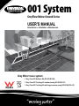
001 System
001
System
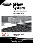
GFlow
System
OIM MANUAL
GreyFlow Below Ground Series
GreyFlow Below Ground Series
USER'S
MANUAL
GreyFlow Above
Ground Series
OIM
OIMMANUAL
MANUAL
Operation ●Introduction
Installation• ●
Maintenance
Installation
• Maintenance
Operation
● Installation
● Maintenance
Operation
● Installation
● Maintenance
GreyWater
waterreuse
reusesystem
system
Grey
IAPMO
Builders
Kit - Kit
Interceptor
& 001 Pit (GF-001-BK)
□ Grey Flow 001
Builder's
(UP-GF-001-BK)
Finishing
Kit (GF-001-FK)
□ Grey
Flowwater
001
Finishing
Kit standard
pump (UP-GF-001-FK)
Grey
reuse
system
Grey
water
reuse
system
001Finishing
CompleteKit
System
GF-001-LP)
□ Grey FlowGFlow
001
with (GF-001/
large
pressure
pump
Builders
Kit
Interceptor
& 001(UP-GF-001-FK-LP)
Pit (GF-001-BK)
(UP-GF-GF)
Finishing Kit (GF-001-FK)
001 Complete System (GF-001/
GF-001-LP)
ONE
YEAR
WARRANTY
INSTALLATION:
IMPORTANT DO’S AND DON’TS:
�������������������������������������
���������������������������������������������������
����������������������������������
���������������������������������
�������������������������������
��������������������������������������������
����������������������������������������������
����������������
���������������������������������������
���������������������
����������������������
���������������������������������������������������������
������������������������������������������������������
�������������������������������������������������������
2
CONTENTS:
INSTALLATION:
CONTENTS
IMPORTANT DO’S AND DON’TS:
INTRODUCTION:
Page 4
Requirements Page 5
INSTALLATION:
Parts List: Grey
Flow 001 System �������������������������������������
Page 6 - 7
���������������������������������������������������
Important Do’s
and Don’ts Page 8 - 10
Step One: Plumbing Installation Page 11 - 14
Step Two: Installing the Grey Flow Electrical Components Page 15 - 18
Step Three: Installing the Grey
Flow Watering System ����������������������������������
Page 19 - 22
TROUBLESHOOTING GUIDE: Page 23 - 24
���������������������������������
�������������������������������
MAINTENANCE: Page 25
TERMS OF WARRANTY: Page 27 - 28
DISCLAIMER: Page 29
��������������������������������������������
����������������������������������������������
����������������
���������������������������������������
���������������������
����������������������
���������������������������������������������������������
������������������������������������������������������
�������������������������������������������������������
3
INTRODUCTION:
INSTALLATION:
Congratulations! You have taken an important step towards an environmentally friendly living
with your purchase of the Universal GREY FLOW 001 Grey Water diversion and reuse system.
The GREY FLOW 001 System is an 'Entire' Grey Water diverter that promotes a cleaner and
healthier environment with its innovative 'no holding tank' design.
IMPORTANT DO’S AND DON’TS:
The GREY FLOW 001 System is especially designed for in-ground installation with Grey Water
diverted through the system for use in the garden through sub-surface irrigation. The 001
System is suitable only for installation where the sewer pipe is between 0 to 2 feet from the
ground level.
Please Note: The 001 System is NOT suitable for the Grey Water from the kitchen
sinks.
�������������������������������������
���������������������������������������������������
Instant diversion to sewer by:
1. Electrical switch (remote control devices are also available)
2. Rain Switch
3. Soil Moisture sensor switch
The soil moisture sensor����������������������������������
switch will help to avoid Grey Water run-off and trigger an automatic
shut down of the system���������������������������������
when the soil is saturated. Please check with authorised dealer for ideal
moisture sensor switch to meet your requirements.
�������������������������������
Manual diversion
of the Grey Water can be achieved by using the supplied rubber plugs to seal
the diversion holes inside the inter-ceptor unit (ref. diagrams overleaf).
The GREY FLOW 001 can be used in conjunction with Water Rotor valve indexer to achieve
water distribution over a number of stations (up to 6).
The GREY FLOW 001 system has Watermark and IAPMO UPC certifications, is approved
for use in all states and could be considered
for government's Grey Water rebates wherever
��������������������������������������������
����������������������������������������������
available.
DEFINITION:
����������������
���������������������������������������
���������������������
Grey Water is wastewater generated from domestic activities such as laundry, shower, and
bathing, which can be recycled on-site for uses such as landscape irrigation and constructed
wetlands. This wastewater contains no fecal matter (human feces). Grey Water differs from
water from toilets which is designated sewage
or blackwater to indicate it contains human waste.
����������������������
���������������������������������������������������������
������������������������������������������������������
�������������������������������������������������������
4
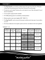
REQUIREMENTS:
INSTALLATION:
The Grey Flow 001 is not suited to conditions where the invert level of the Grey Water pipe
is lower than 2 feet below ground (if lower than 2 feet use PS model instead)
The drip-line must be kept 4" below mulch or soil (check for Local, State, Municipal & Council
laws and regulations)
IMPORTANT DO’S AND DON’TS:
110 volts power supply should be available
PVC/ABS plumbing parts to be installed by a license plumber
Minimum garden area required applies (REF. TABLE 1.0)
The Grey Flow 001 must be turned off during wet conditions and at any sign of accumulation
�������������������������������������
or run-off
���������������������������������������������������
All set-back distances for the irrigation system must be in accordance to the local regulations
TABLE 1.0
Number of
bedrooms in
the house
Assumed
Quantity of
����������������������������������
Minimum garden
number of
Grey Water
Soil Type
area to irrigate in
���������������������������������
people
in the
reuse in
Square Feet
house
Gallons/day
�������������������������������
Sand
2
3
3
4
4
5
5
6
6
7
75
100
90
Loam
130
Clay
185
Sand
115
Loam
180
Clay
230
Sand
160
��������������������������������������������
125
Loam
225
����������������������������������������������
Clay
320
����������������
Sand
185
���������������������������������������
150
Loam
265
���������������������
175
Clay
370
Sand
220
Loam
320
Clay
440
����������������������
Recommended
irrigation area in
Square Feet
230 & 590
320 & 790
395 & 1050
460 & 1180
540 & 1380
���������������������������������������������������������
������������������������������������������������������
�������������������������������������������������������
5
INSTALLATION:
INSTALLAION:
PARTS LIST:
The Grey Flow 001 builder's Kits (UP-GF-001-BK) are supplied with:
1
Fully fitted Grey Flow 001 main pit with PVC interceptors and suction manifold
1
Extra holding bracket to be used only when additional extension is needed
1
Additional pit extension 12 3/4" high supplied in 4 panels
1
Reinforced plastic lockable lid
2
Filters with bottom screw plugs
IMPORTANT
DO’S AND DON’TS:
2
6" screw-in PVC caps
The Grey Flow 001 Finishing Kits (UP-GF-001-FK or UP-GF-001-FK-LP) are supplied with:
1
Oil cooled, thermal protected, submersible pump to be connected as a centrifugal pump
2
1
1
Control box
2
Spare filters
1
Corflute Grey Water warning sign
�������������������������������������
Assembled 1" check valves
���������������������������������������������������
Fully fitted float switch
Grey Water Warning Sign
to be visible at all time
����������������������������������
���������������������������������
The Grey Flow Complete drip-line irrigation Kits (UP-GF-DL-CK) are supplied with:
1
330 feet roll of purple drip-line with integrated large flow (2.2 Gal/Hr) drippers @ 12" spacing
25
1
Punch tool
1
82 feet roll of 1" Low Density purple Polypipe with barb fittings to suit
�������������������������������
Drip-line fittings
The following optional items are also available for purchase on-line or through a retail store:
Approved Back Flow valve
��������������������������������������������
����������������������������������������������
Grey Flow Self-Cleaning Mechanism
(UP-GF-SCM) (helps reducing frequency of filter cleaning from ����������������
once a month to once or twice a year depending on usage)
���������������������������������������
���������������������
GF Rotor 6 stations (UP-GF-RT6)
(allows for sequencial volumetric distribution of the Grey Water into more than one zone)
Grey Flow Station Drip-line Kit (UP-GF-DL-SK) (for use in additional drip-line stations)
����������������������
���������������������������������������������������������
������������������������������������������������������
�������������������������������������������������������
6
INSTALLATION:
INSTALLAION:
PARTS LIST:
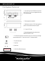
Full System Parts List
10 3/4"
1 Fully fitted Grey Flow 001 Builders Kit (included
13"
dual interceptor with one set of capped filters and a
IMPORTANT DO’S AND DON’TS:
PVC suction manifold
1 Reinforced plastic lockable lid
�������������������������������������
���������������������������������������������������
12 3/4"
1 Additional pit extension 12 3/4" high supplied in 4
panels to be assembled and fitted if required
2 6" screw-in PVC caps
����������������������������������
���������������������������������
1 Extra holding bracket to be used only when
additional extension is used
�������������������������������
1 Oil-cooled thermal protected, submersible pump to be connected as a centrifugal
pump assembles with 2 x 1" brass check valves & 1" discharge manifold
1 Fully fitted float switch
��������������������������������������������
����������������������������������������������
1 Control box
����������������
���������������������������������������
2 Spare filters
���������������������
Grey Water Warning Sign
to be visible at all time
1 Corflute Grey Water warnong sign
����������������������
���������������������������������������������������������
������������������������������������������������������
�������������������������������������������������������
7
INSTALLATION:
INSTALLATION:
IMPORTANT DO’S AND DON’TS
The Grey Flow 001 model is not suited to conditions where the invert level of the Grey Water pipe is lower than 2
IMPORTANT DO’S AND DON’TS:
feet below ground.
If the Grey Water pipe is lower than 2 feet below ground use the Grey Flow PS model instead.
Do not use more than the one extra extension
supplied with the system
�������������������������������������
���������������������������������������������������
����������������������������������
���������������������������������
�������������������������������
��������������������������������������������
����������������������������������������������
����������������
���������������������������������������
���������������������
����������������������
���������������������������������������������������������
������������������������������������������������������
�������������������������������������������������������
8
INSTALLATION:
INSTALLATION:
IMPORTANT DO’S AND DON’TS
IMPORTANT DO’S AND DON’TS
To avoid Grey Water overflow to sewer use all 330 feet of
To avoid grey water overflow to sewer use all 100 metres of
Grey
Flow Dripline*
Drip-line* (100
(330 m)
ft) per
GreyFlow
perstation
station
IMPORTANT DO’S AND DON’TS:
DoDo
notnot
runrun
drip-line
more
thanthan
23 feet
dripline
more
7 metres
from
start
of the
feeder
from
thethe
start
of the
feeder
pipepipe
�������������������������������������
���������������������������������������������������
Use
minimum
1" feeder
Use
minimum
25 mmpipe
feeder pipe
����������������������������������
���������������������������������
�������������������������������
Use
Rotor
valve
a flow
based
indexer
Use GF
3 way
valve
or aorflow
based
indexer
(notpressure
pressurebased)
based)totosplit
splitthe
the
system
into
(not
system
into
morethan
thanone
onestation
station
(this
ensures
that
more
(this
ensures
that
thethe
pumpnever
neverruns
runsagainst
against
closeline)
line)
pump
a aclose
��������������������������������������������
����������������������������������������������
����������������
Maximum
run length
23 feet7 metres
Maximum
run length
���������������������������������������
���������������������
Do
toto
existing
system
or substitute
drip-line
(the
Donot
notconnect
connect
existing
system
or substitute
dripline
supplied
pump pump
and filters
been
sized
tosized
suit the
(the supplied
andhave
filters
have
been
to full
suit330
thefeet
supplied
drip-line
flows and
dripperflows
sizes)and dripper sizes)
full 100 metre
supplied
dripline
** IfIf non
FlowDripline
Drip-lineisisused
used
the
warrantymay
maybebevoid.
void.
non Grey
GreyFlow
the
warranty
����������������������
���������������������������������������������������������
������������������������������������������������������
�������������������������������������������������������
“moving water”
7
9
IMPORTANT DO’S AND DON’TS
INSTALLATION:
INSTALLATION:
IMPORTANT DO’S AND DON’TS
IMPORTANT DO’S AND DON’TS:
Never
thethe
interceptor
trap without
filter
Neverleave
leave
interceptor
trap without
filter
(2
have
beenbeen
provided
for instant
(2extra
extrafilters
filters
have
provided
for instant
�������������������������������������
replacement
at
cleaning
time)
swap at filter cleaning time)
���������������������������������������������������
����������������������������������
���������������������������������
�������������������������������
Make sure to insert the filters all the way
Make sure to insert the filters all the way
down
to the
bottom
of the interceptor
trap
down
to the
bottom
of the interceptor
trap
(the
filter
1/2"1/2
riserinch
should
be should
standingbe
vertically)
(the
filter
riser
standing
vertically)
��������������������������������������������
����������������������������������������������
����������������
���������������������������������������
���������������������
����������������������
���������������������������������������������������������
������������������������������������������������������
�������������������������������������������������������
10
INSTALLATION:
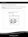
INSTALLATION
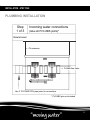
- STEP ONE:
PLUMBING INSTALLATION
IMPORTANT
AND
DON’TS:
Step DO’S
Incoming
water
connections
1 of 3
(Glue all PVC/ABS joints)*
�������������������������������������
���������������������������������������������������
← Pit extension
����������������������������������
���������������������������������
�������������������������������
→ To Back-flow valve
��������������������������������������������
����������������������������������������������
����������������
���������������������������������������
���������������������
Use 4" PVC/ABS DWV pipe joiner for connections
* PVC/ABS glue not included
����������������������
���������������������������������������������������������
������������������������������������������������������
�������������������������������������������������������
11
INSTALLATION:
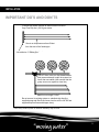
INSTALLATION
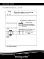
- STEP ONE:
PLUMBING INSTALLATION
Step
Outgoing
water
connections
IMPORTANT
DO’S
AND
DON’TS:
2 of 3
Install approved Back-flow valve
I/O Access (Not supplied with Kit)*
�������������������������������������
Ground Level
���������������������������������������������������
Pipe extension to above
ground level (not supplied
with kit)*
����������������������������������
Approved Back-flow valve
���������������������������������
(not supplied with kit)*
������������������������������� Overflow to sewer
��������������������������������������������
����������������������������������������������
����������������
���������������������������������������
���������������������
* to be purchased separately
����������������������
���������������������������������������������������������
������������������������������������������������������
�������������������������������������������������������
12
INSTALLATION:
INSTALLATION
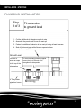
- STEP ONE:
PLUMBING INSTALLATION
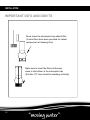
Step
IMPORTANT
DO’S
AND DON’TS:
Pit
extension
3 of 3
to ground level
�������������������������������������
1. Cut the additional pit extension panels to size
���������������������������������������������������
2. Assemble the panels and fit over the main pit
3. Fasten the additional extension to the main pit using at least 8 screws
4. Seal all joints and gaps with silicon or expansion foam
����������������������������������
Ground Level ���������������������������������
Fit the extra holding bracket supplied
Glue
the 6"
�������������������������������
across the top of the main pit to
screw on caps
strengthen the side panels
to the top of the
interceptors
4" Grey Water
pipe from house
��������������������������������������������
����������������������������������������������
����������������
���������������������������������������
���������������������
����������������������
���������������������������������������������������������
������������������������������������������������������
�������������������������������������������������������
13
INSTALLATION:
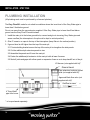
INSTALLATION
- STEP ONE:
PLUMBING INSTALLATION
(All plumbing work must be performed by a licensed plumber)
IMPORTANT DO’S AND DON’TS:
The Grey Flow 001 model is not suited to conditions where the invert level of the Grey Water pipe is
lower than 2 feet below ground.
Do not use more than the one extension supplied. If the Grey Water pipe is lower than2 feet below
ground use the Grey Flow PS model instead.
1. Install the main pit in the below ground hole, connect and glue to incoming Grey Water pipe and
sewer overflow (the interceptors in the pit must be kept in vertical position)
2. Glue 6" screw-in on caps to the top of the interceptors (keep filters in the vertical position)
�������������������������������������
���������������������������������������������������
3. If ground level is still higher then the top of the main pit 3.1Fit extra holding bracket across the top of the main pit to strengthen the side panels
3.2Cut the additional pit extension panels to size
3.3Assemble the panels and fit over the main pit
3.4Fasten the additional pit extension to the main pit with at leasr 8 screws
����������������������������������
3.5Seal all joints and gaps
with silicon paste or expansion foam so as to keep backfill out of the pit
���������������������������������
�������������������������������
I/O Access (not supplied with kit)*
Ground Level
Pipe extension to above ground
level (not supplied with kit)*
4" Grey Water
pipe from house
* to be purchased separately
Approved Back-flow valve (not
supplied with kit)*
��������������������������������������������
����������������������������������������������
Overflow to sewer
����������������
���������������������������������������
���������������������
����������������������
���������������������������������������������������������
������������������������������������������������������
�������������������������������������������������������
14
INSTALLATION:
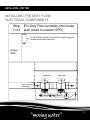
INSTALLATION
- STEP TWO:
INSTALLING THE GREYFLOW
ELECTRICAL
INSTALLING
THECOMPONENTS
GREY FLOW
ELECTRICAL COMPONENTS
IMPORTANT
DON’TS:
Grey AND
Flowcontroller
controller
onto
Step
GreyFlow
ontohouse
house
Step
2/1 FixDO’S
wall (close
1 of 4 wall
(close to
tooutdoor
outdoorGPO)
GPO)
Fix
Flowcontroller
controllerto
tohouse
housewall
wallusing
usingbox
boxlegs
legs
and
FixGrey
GreyFlow
and
screws found
found inside
inside control
control box
box
screws
�������������������������������������
���������������������������������������������������
House
Wall
����������������������������������
���������������������������������
�������������������������������
Filter access
Grey water pipe
connection
Filter access
��������������������������������������������
����������������������������������������������
����������������
���������������������������������������
���������������������
����������������������
���������������������������������������������������������
������������������������������������������������������
�������������������������������������������������������
15
INSTALLATION:
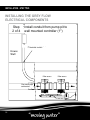
INSTALLATION
- STEP TWO:
INSTALLING THE GREYFLOW
ELECTRICAL
INSTALLING
THECOMPONENTS
GREY FLOW
ELECTRICAL COMPONENTS
IMPORTANT
DO’S
ANDfrom
DON’TS:
Step
conduit
pitpit
to to
Install
conduit
frompump
pump
Step
2/2 Install
2 of 4 wall
wall mounted
mountedcontroller
controller
(25 mm)
(1")
�������������������������������������
���������������������������������������������������
1"
conduit
25electrical
mm electrical
conduit
House
Wall
����������������������������������
���������������������������������
�������������������������������
Filter access
Grey water pipe
connection
Filter access
��������������������������������������������
����������������������������������������������
����������������
���������������������������������������
���������������������
����������������������
���������������������������������������������������������
������������������������������������������������������
�������������������������������������������������������
16
INSTALLATION:
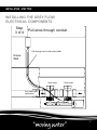
INSTALLATION
- STEP TWO:
INSTALLING THE GREYFLOW
ELECTRICAL
COMPONENTS
INSTALLING
THE GREY
FLOW
ELECTRICAL COMPONENTS
IMPORTANT
DO’S AND DON’TS:
Step
Step
2/3 Pull
wires
wires through
throughconduit
conduit
3 of 4
�������������������������������������
���������������������������������������������������
Pull through sensor and pump cables
House
Wall
����������������������������������
���������������������������������
�������������������������������
Filter access
Filter access
��������������������������������������������
����������������������������������������������
Grey water pipe
����������������
connection
���������������������������������������
���������������������
����������������������
���������������������������������������������������������
������������������������������������������������������
�������������������������������������������������������
17
INSTALLATION:
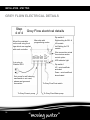
INSTALLATION
- STEP TWO:
GREY FLOW ELECTRICAL DETAILS
IMPORTANT DO’S AND DON’TS:
Step
4 of 4
Grey Flow electrical details
Dip switch 2
Neutral
Earth
Active
any wire
any wire
no wire
Active
Earth
Neutral
Neutral
Earth
Active
Microchip with
Right setting for 001 &
Mount the controller
�������������������������������������
programming codes
US models
on the wall using the 4
���������������������������������������������������
Left Setting for PS
legs which are supplied
models
with each controller
up
Wire connection points
for moisture sensor
control option
����������������������������������
LED indicator light
���������������������������������
down
3 pin plug to
Outdoor
GPO
�������������������������������
Dip switch 1
UP - auto backflush
activated
Down - auto backflush
de-activated
If air pump for self cleaning
mechanism is not used,
please seal grommet
��������������������������������������������
To Grey Flow Float switch
����������������������������������������������
connection
����������������
���������������������������������������
���������������������
To Grey Flow air pump
To Grey Flow Water pump
����������������������
���������������������������������������������������������
������������������������������������������������������
�������������������������������������������������������
18
INSTALLATION:
INSTALLATION
- STEP THREE:
INSTALLING THE GREY FLOW
WATERING SYSTEM
IMPORTANT DO’S AND DON’TS:
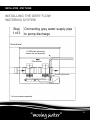
Step
1 of 2
Connecting grey water supply pipe
to pump discharge
�������������������������������������
Ground
level
���������������������������������������������������
1" LDPE barb elbow with
ratchet clip (not supplied)*
����������������������������������
���������������������������������
Filter access
�������������������������������
Double check valve
��������������������������������������������
����������������������������������������������
����������������
���������������������������������������
���������������������
* to be purchased separately
����������������������
���������������������������������������������������������
������������������������������������������������������
�������������������������������������������������������
19
INSTALLATION:
INSTALLATION
- STEP THREE:
INSTALLING THE GREYFLOW
WATERING
INSTALLING
THESYSTEM
GREY FLOW
WATERING SYSTEM
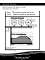
Step
the supply
line to the
Step
3/2 Running
4UFQ
IMPORTANT
DO’S
AND
DON’TS:
3VOOJOHUIFTVQQMZMJOFUPUIF
2 of 2 garden
HBSEFOTFUUJOHVQUIFESJQMJOF
& setting up the drip-line
%SJQMJOFMBZPVUBSPVOEUSFFT
�������������������������������������
���������������������������������������������������
Grey
Flow
(SFZFMPX1VSQMF
ESJQMJOF
Purple
drip-line
.BLFBXIPMFXJUI
Make a whole
QVODIUPPMJOTFSU
with punch tool
%SJQMJOFUBLFPõ
& insert drip-line
fittings
NN-%1&1VSQMF
1"
LDPE Purple
OPUTVQQMJFE
(not supplied)*
����������������������������������
���������������������������������
�������������������������������
%SJQMJOFMBZPVUJOgBSEFOBSFBT
*33*("5*0/"3&"#06/%"3:
Grey Flow
(SFZFMPX1VSQMF
Purple
ESJQMJOF drip-line
��������������������������������������������
����������������������������������������������
����������������
���������������������������������������
.BYJNVNSVOMFOHUIN
Maximum
run length 23 feet
���������������������
.BLFBXIPMFXJUI
Make
a whole with punch tool &
QVODIUPPMJOTFSU
insert
drip-line fittings
%SJQMJOFUBLFPõ
* to be purchased separately
����������������������
���������������������������������������������������������
������������������������������������������������������
�������������������������������������������������������
20
“moving water”
21
INSTALLATION:
INSTALLATION
- STEP THREE:
INSTALLING THE GREY FLOW
WATERING SYSTEM
IMPORTANT DO’S AND DON’TS:
Drip irrigation system layout
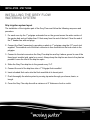
The installation of the irrigation part of the Grey Flow must follow the following sequence and
procedure.
1. For each zone lay the 1" polypipe as header line on the ground across the wider section of
the garden bed and not further than 33 feet away from the end of the bed. Close the end of
the 1" header line with end plugs.
�������������������������������������
2. Connect
the Start Connectors by punching a whole in 1" polypipe using the 0.3" punch tool
���������������������������������������������������
supplied. The smallest end of the start connector is then inserted into the hole made in the
polypipe.
3. Connect to the start connectors the Grey Flow drip-line and lay it above ground in one of the
three layout models (grid, spiral or s-curve). Always keep the drip-line as close to the plant as
����������������������������������
possible. Leave the end of the drip-line open.
���������������������������������
4. Stake the Grey Flow drip-line to the ground every 3'-4".
�������������������������������
5. Connect the end of the drip-lines into a 1" Polypipe flush manifold.
6. Insert a barbed flush valve into the flush manifold at its lowest point.
7. Flush thoroughly the whole system by running tap water through you shower, basin, or
trough.
��������������������������������������������
8. Cover the Grey Flow drip-line with����������������������������������������������
a minimum of 4" thickness of soil or mulch.
����������������
���������������������������������������
���������������������
����������������������
���������������������������������������������������������
������������������������������������������������������
�������������������������������������������������������
21
INSTALLATION:
INSTALLATION
- STEP THREE:
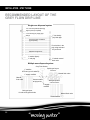
RECOMMENDED LAYOUT OF THE
GREY FLOW DRIP-LINE
Single zoneAND
dispersal system
IMPORTANT DO’S
DON’TS:
1/2" vacuum breaker/air bleed @
highest point (if required)
1" low density poly supply pipe
1" low density
poly flush pipe
fittings
Drip-Line Purple 2.2 Gal/Hr
@ 12" spacing
�������������������������������������
���������������������������������������������������
Punch a hole in the
poly using enclosed
1/4" punch tool
Maximum length 23'-0"
1" ratchet clippoly
1" barbed manual
1" end plug
����������������������������������
flush valve
���������������������������������
Multiple zone dispersal system
�������������������������������
Grey Flow diverter
1" mainline
GF Rotor (up to 6 stations)
1" supply manifold
Manual
flush valve
Spiral type Layout
for trees
Manual flush valve
Vacuum treaker
Grid type layout for
at high
points
��������������������������������������������
sub-surce lawns
����������������������������������������������
1" supply
����������������
manifold
���������������������������������������
���������������������
Grid type layout
for sub-mulch garden beds
Manual flush valve
Flush manifold
����������������������
���������������������������������������������������������
������������������������������������������������������
�������������������������������������������������������
22
INSTALLATION:
TROUBLESHOOTING
GUIDE:
TROUBLESHOOTING GUIDE
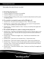
A. Normal Operating Sequence:
IMPORTANT DO’S AND DON’TS:
1. Controller LED light is off (no power to the controller)
2. Controller LED light is on (no water is detected)
3. Controller LED light is flashing and the pump is on (water has been detected and the system
is in operating mode)
B. The controller is connected to power and the LED light is off :
�������������������������������������
1. Potential
Cause - No power at power supply point. Action - Check power supply.
���������������������������������������������������
2. Potential Cause - Fuse has blown. Action - Replace fuse (you need a 3.15 amp slow blow
fuse – there are available at your local electronic store).
3. Potential Cause - Controller is defective. Action - Contact your local Grey Flow supplier with
proof of purchase.
����������������������������������
C. The controller LED���������������������������������
light is on, water is running, but the pump is off :
1. Potential Cause - The plugs are still attached to the filters and do not allow the water to reach
�������������������������������
the sensor switch. Action - Unscrew and remove plugs from filter base and reinstall filters in
their original location.
2. Potential Cause - The filters are clogged. Action - Clean filters and reinstall filters in their
original location.
3. Potential Cause - The sensor is not connected. Action - Connect sensor wires.
��������������������������������������������
����������������������������������������������
����������������
5. Potential Cause - The sensor is stuck
in the open position (debris can affect the operation of
���������������������������������������
the sensor). Action - Pull out sensor from holding tee, clean sensor and the inside of the tee
���������������������
4. Potential Cause - The air vent is closed or clogged. Action - Open up air vent tubing to air.
and reinstall sensor in original position.
6. Potential Cause - The sensor is defective. Action - Contact your local Grey Flow supplier with
proof of purchase.
����������������������
���������������������������������������������������������
������������������������������������������������������
�������������������������������������������������������
23
INSTALLATION:
TROUBLESHOOTING
GUIDE:
TROUBLESHOOTING GUIDE
D. The controller LED light is flashing but the pump is not running:
1. Potential Cause - The pump cables are not connected properly. Action - Connect pump wire
properly.
IMPORTANT DO’S AND DON’TS:
2. Potential Cause - The impeller of the pump does not rotate (large debris and hair can be the
cause). Action - Remove pump from pit, open casing and clear all debris and hair that may
be stopping the impeller from turning. Reinstall pump in its original position.
3. Potential Cause - The pump is defective. Action - Contact your local Grey Flow supplier with
proof of purchase.
4. Potential
Cause - The controller is defective. Action - Contact your local Grey Flow supplier
�������������������������������������
with proof
of purchase.
���������������������������������������������������
E. The controller is operating normally, all taps in the house are off, but the pump
is turning on and off on regular basis:
1. Potential Cause - There is a tap leaking in the house. Action - Check if water is flowing into
the interceptor trap by looking into the filter chamber. If water is detected find and fix leaky
tap inside the house.����������������������������������
���������������������������������
2. Potential Cause - The check valves on the discharge of the pump are not closing properly.
Action�������������������������������
- Remove check valve and thoroughly wash all parts.
F. The controller is operating normally, water in the house is off, but the pump is
on all the time:
1. Potential Cause - The sensor wires are shorting. Action - Make sure that the sensor switch
wires are not shorting.
2. Potential Cause - The sensor switch
is installed in the wrong position. Action - Twist the
��������������������������������������������
sensor switch so that the white marking
on the sensor stem is facing upward.
����������������������������������������������
����������������
3. Potential Cause - The sensor switch
is stuck in the close position. Action - Pull out sensor
���������������������������������������
from holding tee, clean sensor and
the inside of the tee and reinstall sensor in original
���������������������
position.
4. Potential Cause - The controller is defective. Action - Contact your local Grey Flow supplier
with proof of purchase.
����������������������
���������������������������������������������������������
������������������������������������������������������
�������������������������������������������������������
24
INSTALLATION:
MAINTENANCE:
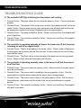
RECOMMENDED MAINTENANCE
To retain the original reliability and performance of the Grey Flow 001 System the following
maintenance procedure should be followed. Please ensure that you wash your hands thoroughly
after contact with Grey Water or handling any part of the Grey Flow System.
IMPORTANT DO’S AND DON’TS:
The following maintenance steps should be carried out once a month and not less
than every 3 months:
A) Open top cover of the interception unit.
B) Remove primary sponge filter and wash thoroughly in a bucket, with a garden hose or in any
basin not connected to the dedicated grey water line.
�������������������������������������
C) Open the
lid of the secondary filter located in the underground pit, remove lint filter and wash
���������������������������������������������������
thoroughly with fresh water from the same source of water as in b.
D) Flush thoroughly the whole system by running tap water through your shower, basis or
trough.
E) The Grey Flow 001 System is ready to operate again.
����������������������������������
The following maintenance
steps should be carried out once a year:
���������������������������������
A) Remove and clean primary
and secondary sponge filters.
B) Re-insert
the filters (filters may need replacing on an annual basis).
�������������������������������
C) Unscrew the sensor switch from its location on the suction of the pipe and rinse thoroughly
(ensure the system is turned off ).
D) Ensure that the sensor is still off and thoroughly flush the suction lines by pouring water
through the filters. Make sure to remove all debris and hair.
E) Re-insert and screw in sensor switch (do not change the original positioning and direction of
��������������������������������������������
the sensor switch).
����������������������������������������������
F) Remove & clean one way valves ����������������
downstream of the pump.
���������������������������������������
G) Turn on the pump and run water ���������������������
and a little chlorine through the entire system for at least five
minutes.
H) Top up mulch over the Grey Flow drip-line to a minimum depth of 4" (the Grey Flow Drip-line
will need to be replaced every 5 to 8 years).
����������������������
���������������������������������������������������������
������������������������������������������������������
�������������������������������������������������������
25
INSTALLATION:
IMPORTANT DO’S AND DON’TS:
�������������������������������������
���������������������������������������������������
����������������������������������
���������������������������������
�������������������������������
��������������������������������������������
����������������������������������������������
����������������
���������������������������������������
���������������������
����������������������
���������������������������������������������������������
������������������������������������������������������
�������������������������������������������������������
26
INSTALLATION:
AWWS USA LIMITED CONSUMER WARRANTY
IMPORTANT DO’S AND DON’TS:
ONE YEAR LIMITED WARRANTY
AWWS USA, LLC ("AWWS") warrants this product against material defects in materials and
workmanship for a period of ONE YEAR from the date of original retail purchase ("warranty
period"). Warranty work will be done in accordance with the following terms and conditions.
This warranty only benefits the original purchaser.
�������������������������������������
THIS WARRANTY
COVERS ONLY DEFECTS IN MATERIAL AND WORKMANSHIP.
���������������������������������������������������
THIS WARRANTY DOES NOT COVER ANY OF THE FOLLOWING:
1. Expendable items that can wear out from normal use, including but not limited to, filters or
similar perishable parts.
����������������������������������
2. Damage to or failure of this System if it is not installed, operated, or maintained according to
���������������������������������
all instructions supplied with the System.
3. Damage
to or failure of this System resulting from accident, abuse, misuse, or use for other
�������������������������������
than its intended purpose, Act of God.
4. Damage to or failure of parts or systems resulting incomplete or improper installation or from
unauthorized modifications made to this System.
5. If you purchased the System from an unauthorized retailer or dealer.
6. Damage caused by power surges, electrical storm damage, incorrect power supply, or insect
��������������������������������������������
or vermin infestation.
����������������������������������������������
7. Damage to or failure of parts if this
System is serviced or repaired by anyone other than an
����������������
���������������������������������������
Authorized Service Center.
���������������������
8. This warranty extends only to you, the original purchaser. It is not transferable to anyone
who subsequently purchased this product from you.
9. Use for more than a single family or use in a commercial establishment or for commercial
non-household purposes.
����������������������
���������������������������������������������������������
������������������������������������������������������
�������������������������������������������������������
27
INSTALLATION:
10. Parts and Systems not supplied by AWWS USA are not covered by this warranty.
Any item which has been repaired or replaced under this warranty shall be covered for the
remainder of the original warranty as extended by the number of days that the product has been
out of your hands for repair.
IMPORTANT DO’S AND DON’TS:
YOUR RESPONSIBILITY
The above limited warranties are subject to the following conditions:
You must provide your original bill of sale, invoice or other proof of purchase of the System
�������������������������������������
showing that
you are the original purchaser, that the purchase was made within one year of the
���������������������������������������������������
date of your claim and that you purchased it from an authorized dealer or retailer. No warranty
work will be done without this information. Keep a copy of your receipt or invoice for your own
records.
These limited warranties are effective only if this System is purchased and used in the United
����������������������������������
States.
���������������������������������
Labor and service charges for warranty repair, installation, set up, and adjustment of customer
controls are
not covered by these limited warranties.
�������������������������������
Should you encounter a defect in the System, go to WWW.AWWS.US to find the closest
authorized service center. Contact the center and it will arrange for an inspection and corrective
action, if needed and if covered by this warranty.
Should the center determine that the System is not covered by this warranty; any corrective work
will be performed at your request and��������������������������������������������
at your expense. If the center makes a second and/or
����������������������������������������������
subsequent visit and determines that����������������
there is no problem or that the System is not covered, the
service call will be charged to you. ���������������������������������������
���������������������
When making a warranty claim, please be prepared to provide a description of the System,
your name, address, work day telephone number, a description of the problem, the date you
purchased the System and the identify of the seller.
����������������������
���������������������������������������������������������
������������������������������������������������������
�������������������������������������������������������
28
INSTALLATION:
DISCLAIMER OF IMPLIED WARRANTIES; LIMITATION OF REMEDIES
1. ALL IMPLIED WARRANTIES, INCLUDING IMPLIED WARRANTIES OF
MERCHANTABILITY AND FITNESS FOR A PARTICULAR PURPOSE, ARE LIMITED IN
DURATION TO ONE YEAR FROM THE DATE YOU PURCHASED THE PRODUCT.
IMPORTANT DO’S AND DON’TS:
2. NEITHER AWWS NOR ITS AFFILIATES ARE RESPONSIBLE OR LIABLE FOR ANY
LOSS, INCONVENIENCE OR DAMAGE, WHETHER SPECIAL, EXEMPLARY, DIRECT,
INCIDENTAL, CONSEQUENTIAL OR OTHERWISE, AND WHETHER KNOWN OR
SHOULD HAVE BEEN KNOWN TO AWWS, INCLUDING DAMAGE TO OR REPLACEMENT
OF OTHER EQUIPMENT AND PROPERTY AND PERSONAL INJURY RESULTING
FROM ANY BREACH OF WARRANTY, THE INABILITY TO USE THE PRODUCT OR
UNDER
ANY LEGAL THEORY IN CONTRACT OR TORT. THESE WARRANTIES AND
�������������������������������������
REMEDIES ARE THE SOLE AND EXCLUSIVE WARRANTIES AND REMEDIES GIVEN BY
���������������������������������������������������
AWWS IN CONNECTION WITH THE SALE AND USE OF THE PRODUCT. NO OTHER
WARRANTIES, ORAL OR WRITTEN, EXPRESS OR IMPLIED ARE GIVEN.
3. IN ANY EVENT, AWWS'S ENTIRE LIABILITY SHALL BE LIMITED TO THE ACTUAL
PURCHASE PRICE YOU PAID TO THE RETAIL SELLER OF THE DEFECTIVE PRODUCT.
THIS LIMITATION APPLIES
WHETHER DAMAGES ARE SOUGHT OR A CLAIM MADE,
����������������������������������
UNDER THIS WARRANTY
OR AS A TORT CLAIM (INCLUDING NEGLIGENCE AND
���������������������������������
STRICT PRODUCT LIABILITY), A CONTRACT CLAIM OR ANY OTHER CLAIM. THIS
�������������������������������
LIMITATION
CANNOT BE WAIVED OR AMENDED BY ANY PERSON. THIS LIMITATION
OF LIABILITY IS EFFECTIVE EVEN IF AWWS OR ANY AUTHORIZED REPRESENTATIVE
OF AWWS HAS BEEN ADVISED BY YOU OF THE POSSIBILITY OF SUCH DAMAGES.
THIS LIMITATION OF LIABILITY, HOWEVER, SHALL NOT APPLY TO CLAIMS OF
PERSONAL INJURY.
4. Some states do not allow the exclusion or limitation of implied warranties or liability
for incidental or consequential��������������������������������������������
damages, or do not allow a limitation on how long an
����������������������������������������������
implied warranty lasts, so the above
limitations or exclusions may not apply to you.
����������������
You are advised to contact applicable
state laws for a full determination of your rights.
���������������������������������������
���������������������
This warranty gives you specific
legal rights, and you may have other rights which
vary from state to state.
5. No AWWS dealer, agent or employee is authorized to make any modification, extension,
change or amendment to this warranty.
����������������������
���������������������������������������������������������
������������������������������������������������������
�������������������������������������������������������
29
INSTALLATION:
IMPORTANT DO’S AND DON’TS:
�������������������������������������
���������������������������������������������������
����������������������������������
���������������������������������
�������������������������������
Head Office USA
9901 San Fernando Rd. #33
Los Angeles, CA 91331
Phone: (310) 869-7676
www.awws.us
��������������������������������������������
����������������������������������������������
����������������
���������������������������������������
���������������������
IAPMO
����������������������
���������������������������������������������������������
������������������������������������������������������
�������������������������������������������������������