1
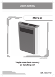
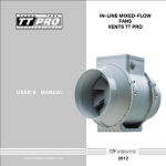
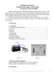
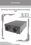
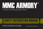
USER’S MANUAL
VUT 100 P mini
Heat recovery air handling unit
VUT 100 P mini
2
CONTENTS
Safety requirements
Introduction
Use
Delivery set
Designation key
Main technical parameters
Design and operating logic
Mounting and set-up
Condensate drain
Connection to power mains
Unit control
Maintenance
Troubleshooting
Storage and transportation rules
Manufacturer's warranty
Acceptance certificate
Seller's information
Mounting certificate
Warranty Card
3
5
5
5
5
6
7
8
8
9
9
10
11
11
12
13
13
13
14
3
SAFETY REQUIREMENTS
•
•
•
•
•
•
Read the user’s manual carefully prior to the operation and installation of the heat recovery air handling unit, hereinafter the
unit.
Installation and operation of the unit shall be performed in accordance with the present user’s manual as well as the provisions
of all the applicable local and national construction, electrical and technical codes and standards.
The warnings contained in the user’s manual must be considered most seriously since they contain vital personal safety
information.
Failure to follow the safety regulations may result in an injury or unit damage.
Read the manual carefully and keep it as long as you use the unit.
While transferring the unit control the user’s manual must be turned over to the receiving operator.
Symbol legend used in the manual:
WARNING!
DO NOT!
UNIT MOUNTING SAFETY PRECAUTIONS
The unit must be disconnected from the power
supply prior to every installation or repair
operation.
The unit must be grounded!
The unit must not be operated outside the
temperature range stated in the user's manual
or in aggressive or explosive environments.
Do not use damaged equipment or
conductors to connect the unit to power
mains.
While installing the unit follow the safety
regulations specific to the use of electric tools.
Unpack the unit with care.
Do not change the power cord length at your
own discretion. Do not bend the power cord.
Avoid damaging the power cord.
Do not position any heating devices or other
equipment in close proximity to the unit
power cord.
VUT 100 P mini
4
UNIT OPERATION SAFETY PRECAUTIONS
Do not touch the unit controls with wet hands.
Do not carry out the unit maintenance with
wet hands.
Do not wash the unit with water. Protect
the unit electric parts from water ingress.
Use the unit only as intended by the
manufacturer. Do not connect a clothes dryer
or other similar equipment to the ventilation
system.
Do not put any water containers on the unit.
i.e. flower vases.
ON
Disconnect the unit from power supply prior
to maintenance.
Do not sit on the unit and do not put any
objects on it.
OFF
Do not let children operate the unit.
Do not damage the power cable while
operating the unit. Do not put any objects
on the power cable.
Keep combustible gases and inflammable
products away of the unit.
Do not open the operating unit.
In case of unusual sounds, smoke disconnect
the unit from power supply and contact the
service centre.
During long-term operation of the unit
periodically check the mounting for
reliability.
Do not block the air duct when the unit is on.
Do not let air flow from the unit be directed
to the open flame devices or candles.
5
INTRODUCTION
This user’s manual includes technical description, operation, installation and mounting guidelines, technical data for the heat
recovery air handling unit VUT 100 P mini.
USE
The heat recovery unit is designed to save heat energy by means of heat energy utilization and is one of the energy saving components
used in buildings and premises.
The unit is a component unit and is not designed for independent operation.
The unit enables continuous air exchange by means of mechanical ventilation in private residences, offices, hotels, cafes, conference
rooms as well as recovery of the waste heat energy contained in the extract air to warm up the clean supply air.
The unit is designed for wall mounting.
The unit is rated for continuous operation always connected to power mains.
Transported air must not contain any flammable or explosive mixtures, evaporation of chemicals, coarse dust, soot and oil particles,
sticky substances, fibrous materials, pathogens or any other harmful substances.
THE UNIT IS NOT INTENDED TO BE USED BY CHILDREN, PHYSICALLY
OR MENTALLY DISABLED PERSONS, PERSONS WITH SENSORY DISORDER,
PERSONS WITH NO APPROPRIATE QUALIFICATION.
THE UNIT INSTALLATION SITES MUST PREVENT ACCESS BY UNATTENDED
CHILDREN.
DELIVERY SET
Unit
1 item
User's manual
1 item
Speed switch
1 item
Packing box
1 item
DESIGNATION KEY
VUT 100 P mini
Casing type:
compact casing
Modification:
P - suspended-mounted
Air capacity [m3/h]
Unit type:
VUT - heat recovery ventilation
VUT 100 P mini
6
MAIN TECHNICAL PARAMETERS
The unit is designed for indoor application with the ambient temperature ranging from +1 °C up to +40 °C and relative humidity up
to 80%. The transported air temperature must be within -25 °C up to +50° C.
The unit is classified as a class I electric appliance.
Hazardous parts access and water ingress protection standard:
Unit motors - IP 44;
Unit assembly connected to air ducts - IP 22.
The unit design is regularly improved, so some models may slightly differ from those ones described in this manual.
UNIT OVERALL DIMENSIONS, MM
595
397
96
105
164
212
UNIT TECHNICAL DATA
Model
VUT 100 P mini
Speed
low
Supply voltage, 50 Hz [V]
Total unit current [A]
Air capacity [m /h]
3
RPM [min ]
-1
Noise level, [dB(A)]
Max. transported air temperature [°C]
Casing material
30
38
56
0,18
0,23
0,34
57
78
106
1300
1950
2500
24
32
41
from -25 up to +50
Zinc aluminium
Insulation
polyethylene foam 15 mm
extract
G4
supply
G4
Connected air duct diameter [mm]
Ø125
Weight [kg]
13,0
Heat recovery efficiency [%]
Heat exchanger type
Heat exchanger material
high
1 ~ 230
Power [W]
Filter:
medium
from 65 up to 76
Cross flow
Plastic
404
7
DESIGN AND OPERATING LOGIC
The unit has the following operating logic:
Warm stale extract air from the room flows through the air ducts to the unit, where it is filtered, then air flows through the heat
exchanger and is exhausted outside by the extract fan through the air ducts.
Clean cold air from outside is moved by the supply fan to the unit, where from it is directed to the supply filter. Then filtered air flows
through the heat exchanger and moves to the room through the air ducts.
Heat energy of warm extract air is transferred to clean intake fresh air from outside and warms it up. Heat recovery minimizes thermal
energy losses, energy demand and operating costs for air heating accordingly.
UNIT OPERATING LOGIC
(TOP VIEW)
SUPPLY AIR
EXTRACT AIR
EXHAUST AIR
INTAKE AIR
Extract fan
Drain pan
Thermostat
Heat exchanger
fan
The freeze protection thermostat is installed in the exhaust air duct downstream of the heat exchanger. In case of a freeze danger the
thermostat switches the supply fan off and the heat exchanger is warmed up with warm extract air flow. Rotate the thermostat control
knob to set the operation temperature of the thermostat sensor. The thermostat set point is selected individually depending on the unit
operating specifics.
The recommended thermostat operating temperature is +3 °C (factory setting).
VUT 100 P mini
8
MOUNTING AND SET-UP
The unit is designed for suspended mounting by means of the threaded rod fixed in the threaded dowel pin.
While mounting the unit provide the minimum required access to the unit for maintenance and repair. The required minimum
distances from the unit to the wall is shown below.
UNIT MOUNTING
min 10 mm
Mounting example
Nut
Washer
Vibration-absorbing rubber
Nut and lock-nut
min 300 mm
min 400 mm
Precautions:
The unit is designed for mounting on a rigid and stable structure.
The unit is mounted with anchor bolts. Make sure that a mounting construction has sufficient load capacity matching the unit weight.
Otherwise reinforce an installation place by beams, etc.
If the threaded bolts used for the unit mounting are too short the unit can generate abnormal noise and resonate with the ceiling. The
suspended bolts must be long enough to prevent resonating.
If the unit connection place to the spiral seam duct is supposed to be the source of abnormal noise, install a flexible air duct instead of the
flexible one. Optionally the flexible connectors may also be used to prevent resonating.
CONDENSATE DRAINAGE
The condensate drain pan has pipes for extracting the condensed fluid outside the unit.
Connect the pipe, U-trap (not included in delivery package) and sewage collection system with metal, plastic or rubber connecting
pipes and. The pipe slope downwards must be at least 3°. Fill up the system with water before connecting the unit to the power mains! The
U-trap must be filled with water at all times during the unit operation. Make sure that the water flows freely into the sewage collection
system or otherwise condensed water may build up in the unit during the heat exchanger operation which, in turn, may cause equipment
failure and water ingress into the premises.
The condensate drainage system is designed for normal operation in premises with air temperatures above 0 °C. If the expected air
temperatures are below 0 °C the condensate drainage system must be equipped with heat insulation and pre-heating facilities.
CONDENSATE DRAINAGE ARRANGEMENT
min 3°
Drain pipe
Pipe
U-trap
Pipe
Sewage system
9
CONNECTION TO POWER MAINS
DISCONNECT THE UNIT FROM POWER MAINS PRIOR TO ANY ELECTRIC
INSTALLATION OPERATIONS. CONNECT THE UNIT TO A CORRECT INSTALLED
SOCKET WITH A GROUNDED TERMINAL. ANY INTERNAL CONNECTION
MODIFICATIONS ARE NOT ALLOWED AND RESULT IN WARRANTY LOSS.
The unit is rated for connection to single-phase ac 230 V / 50 Hz power mains.
The unit is connected to power supply with a prewired power cable with a plug. In case of need to connect a longer cable follow the
wiring diagram below.
The unit must be connected to power mains with insulated, durable and heat-resistant conductors (cables, wires) with minimum cross
section 0.75 mm2.
Connect the unit to power mains on the terminal block located in the terminal box in compliance with the wiring diagram below and
terminal marking. The terminal marking is shown inside of the terminal box. The unit terminal clamps are marked according to the marking
on the wiring diagram.
Route the wires to the terminal box through the stepped grommet on the unit side panel to preserve the electrical protection class.
Connect the unit to power mains through the external automatic circuit breaker with magnetic trip integrated into the fixed wiring
system with the rated current not below 1 A.
WIRING DIAGRAM
L
N
PE
~ 230 V,
50 Hz
QF
3
2
1
S1
L
N
PE
SL
LOW
1
MIDDLE 2
HIGH
3
C
X1
1
2
3
4
5
6
7
8
QF - automatic circuit breaker (not included into the delivery set).
S1 - speed switch.
X1 - terminal block.
UNIT CONTROL
Air flow is controlled with the speed switch P3-1/300. To activate the required unit speed set the control knob to a respective position
according, see the figure below.
1
2
OFF
1
OFF
— unit is on
3
— unit runs at low speed
3
— unit runs at medium speed
2
OFF
1
3
2
3
1
2
OFF
1
OFF
2
3
— unit runs at high speed
VUT 100 P mini
10
MAINTENANCE
DISCONNECT THE UNIT FROM POWER SUPPLY PRIOR TO MAINTENANCE.
The unit must undergo technical maintenance 3 to 4 times a year. Maintenance includes general cleaning of the unit and the following
operations:
1. Filter maintenance.
Contaminated filters increase air resistance thus impairing supply air delivery into the premises.
The filters should be cleaned as they get dirty, but at least 3-4 times a year. Vacuum cleaning for the air filters is allowed. After two
consecutive cleaning the filters must be replaced. For new filters contact your Seller.
FILTER PULLING PROCEDURE
1. Remove four triangular screws.
2. Remove the filter covers.
3. Pull the filters downwards to remove.
1
2
3
2. Heat exchanger maintenance.
Even regular technical maintenance may not completely prevent dirt accumulation on the heat exchanger casing. Clean the heat
exchanger on a regular basis to ensure high heat recovery efficiency. To clean the heat exchanger remove it from the unit and wash with
warm neutral detergent solution. Re-install the dry heat exchanger into the unit.
HEAT EXCHANGER REMOVAL AS FOLLOWS
DISCONNECT THE DRAIN PIPE PRIOR TO HEAT EXCHANGER MAINTENANCE.
1. Undo four clips.
2. Remove the service panel.
3. Turn the retaining support to loosen and remove the heat exchanger.
1
2
3
11
3. Fan maintenance (once a year).
Even regular technical maintenance may not completely prevent dirt accumulation in the fans which reduces the fan capacity and
impairs supply air delivery into the premises.
Clean the fans with rugs or a soft brush. Do not use water, aggressive solvents or sharp objects as they may damage the impeller.
4. Condensate drain check (once a year).
The condensate drain (line) may get clogged by dirt and dust particles contained in the exhaust air. Check the drain line operation by
filling the drain pan under the unit with water, clean the U-trap and the drain line, if necessary.
5. Fresh air supply duct check (twice a year).
The supply duct grille may get clogged with leaves and other objects reducing the unit performance and supply air delivery. Check the
supply duct grill twice a year and clean it as required.
6. Duct system check (every 5 years).
Even regular fulfilling of all the prescribed above maintenance operations may not completely prevent dirt accumulation in the air ducts
which reduces the unit capacity. The air duct maintenance includes their periodic cleaning or replacement.
TROUBLESHOOTING
Possible faults and troubleshooting
Fault
The fan does not start
up during the unit
start-up.
Automatic switch
tripping following the
unit turning on.
Low air flow.
Low supply air
temperature.
High noise, vibration.
Water leakage.
Possible reasons
Fault handling
No power supply.
Make sure that the unit is properly connected to
power mains and make any corrections, if necessary.
Motor is jammed, the impeller are
clogged.
Turn the unit off. Troubleshoot the motor jam and
the impeller clogging. Clean the blades. Restart the
unit.
Overcurrent resulted from short circuit
in the electric circuit.
Turn the unit off. Contact the service centre.
Low set fan speed.
Set higher speed.
The filters, the fans or the heat
exchanger are dirty.
Clean or replace the filter, clean the fans and the
heat exchanger.
The ventilation system components (air Clean or replace the ventilation system
ducts, diffusers, louver shutters, grilles) components, such as air ducts, diffusers, louver
are clogged or damaged.
shutters, grilles.
The extract filter is soiled.
Clean or replace the extract filter.
The heat exchanger is frozen.
Check the heat exchanger condition. Turn the unit
off and restart it after the freeze danger is no longer
imminent.
The impeller(s) are soiled.
Clean the impeller(s)
The fan or casing screw connection is
too loose.
Tighten the fan or casing screw connection against
stop.
No anti-vibration dampers.
Install anti-vibration rubber mounts.
The drain pipe is clogged, damaged or
wrong mounted.
Clean the drain line, if necessary. Check the drain
line slant, inspect the U-trap and make sure the
drain line is equipped with frost protection.
STORAGE AND TRANSPORTATION RULES
Store the unit in the manufacturer’s original packing box in a dry ventilated premise at the temperatures from +5 °C up to +40 °C and
relative humidity up to 80%.
Storage environment must not contain aggressive vapours and chemical mixtures provoking corrosion, insulation and sealing
deformation.
Use hoist machinery for handling and storage operations to prevent the unit damage.
Fulfil the handling requirements applicable for the applicable freight type.
Transportation with any vehicle type is allowed provided that the unit is protected against mechanical and weather damage.
Avoid any mechanical shocks and strokes during handling operations.
VUT 100 P mini
12
MANUFACTURER’S WARRANTY
The manufacturer hereby warrants normal operation of the unit over the period of 24 months from the retail sale date provided the
user’s observance of the transportation, storage, installation and operation regulations.
Should any malfunctions occur during the unit operation through the manufacturer’s fault during the warranty period the user is
entitled to elimination of faults by means of warranty repair performed by the manufacturer.
The warranty repair includes works specific to elimination of faults in the unit operation to ensure its intended use by the user within
the warranty period.
The faults are eliminated by means of replacement or repair of the complete unit or the faulty part thereof.
The warranty repair does not include:
•
Routine maintenance;
•
Unit installation / dismantling;
•
Unit setup.
To benefit from warranty repair the user must provide the unit, the user’s manual with stamped sale date and the payment document
certifying the purchase.
The unit model must comply with the one stated in the user’s manual.
Contact your Seller for warranty service.
The manufacturer’s warranty does not apply to the following cases:
•
User’s failure to provide the unit with the entire delivery package as stated in the user’s manual or with missing component parts
previously dismounted by the user;
•
Mismatch of the unit model and make with the respective details stated on the unit packing and in the user’s manual;
•
User’s failure to ensure timely technical maintenance of the unit;
•
External damage to the casing (excluding external modifications of the unit as required for its installation) and the internal
components of the unit;
•
Alteration of the unit design or engineering changes of the unit;
•
Replacement and use of the unit assemblies, parts and components not approved by the manufacturer;
•
Unit misuse;
•
User’s violation of the unit installation regulations;
•
User’s violation of the unit control regulations;
•
Unit connection to the power pains with a voltage different from the one stated in the user’s manual;
•
Unit breakdown due to voltage surges in the power mains;
•
User’s discretionary repair of the unit;
•
Unit repair performed by any non-authorised by the manufacturer persons;
•
Expiry of the unit warranty period;
•
User’s violation of the established regulations specific to the unit transportation;
•
User’s violation of the unit storage regulations;
•
Wrongful acts against the unit committed by third persons;
•
Unit breakdown due to circumstances of insuperable force (fire, flood, earthquake, war, hostilities of any kind, or blockade);
•
Missing seals if provided by the user’s manual;
•
Failure to provide the user’s manual with the sale date stamp;
•
Missing payment document certifying the unit purchase.
FOLLOWING THE REGULATIONS STIPULATED HEREIN WILL ENSURE A LONG AND
TROUBLE-FREE OPERATION OF THE UNIT.
USERS’ CLAIMS SHALL BE SUBJECT TO REVIEW ONLY UPON PRESENTATION OF
THE UNIT, THE PAYMENT DOCUMENT AND THE USER’S MANUAL WITH THE SALE DATE
STAMP.
13
ACCEPTANCE CERTIFICATE
Product Type
Heat recovery air handling unit
Model
VUT 100 P mini
Serial number
Manufacturing date
Is recognized as serviceable.
The product complies with the requirements according to the EU norms and directives, to the relevant EU-Low Voltage Equipment Directives, EUDirectives on Electromagnetic Compatibility.
We hereby declare that the following product complies with the essential protection requirements of Electromagnetic Council Directive 2004/108/EC,
89/336/EEC and Low Voltage Directive 2006/95/EC, 73/23/EEC and CE-marking Directive 93/68/EEC on the approximation of the laws of the Member
States relating to electromagnetic compatibility. This certificate is issued following test carried out on samples of the product referred to above.
Assessment of compliance of the product with the requirements relating to electromagnetic compatibility was based on the following standards.
Quality Inspector’s
Stamp
SELLER’S INFORMATION
Shop name
Address
Telephone
E-mail
Sales date
This is to certify delivery of the complete unit with the user's manual. The warranty terms are
acknowledged and accepted.
Customer's signature
Seller’s seal
MOUNTING CERTIFICATE
The heat recovery air handling unit VUT 100 P mini has been connected to power mains pursuant to the
requirements stated in the present user's manual.
Company name
Address
Telephone
Installation technician's
full name
Installation date:
Signature:
This is to certify that the works specific to the unit installation have been performed in accordance
with all the applicable provisions of local and national construction, electrical and technical codes and
standards. The unit operates normally as intended by the manufacturer.
Signature:
Installation technician’s
company seal
VUT 100 P mini
14
WARRANTY CARD
Product type
Model
The heat recovery air handling unit
VUT 100 P mini
Serial number
Manufacturing date
Sales date
Warranty period
Sales company
Seller’s seal
______________________________________________________________________________________________________
______________________________________________________________________________________________________
______________________________________________________________________________________________________
______________________________________________________________________________________________________
______________________________________________________________________________________________________
______________________________________________________________________________________________________
______________________________________________________________________________________________________
_________________________________________________________________________________________________
2013
V59EN-04