1
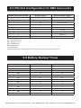
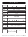
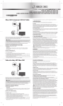
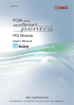
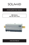
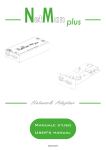
Uninterruptible Power Systems
SDU Series
500, 850, 500-5, 850-5
Instruction Manual
Clearwater Tech - Phone: 800.894.0412 - Fax: 208.368.0415 - Web: www.clrwtr.com - Email: [email protected]
While every precaution has been taken to ensure accuracy and completeness in this
manual, SolaHD assumes no responsibility, and disclaims all liability for damages resulting
from use of this information or for any errors or omissions.
©2008 SolaHD. All rights reserved throughout the world. Specifications are subject to
change without notice.
®SolaHD name and logo are registered trademarks of EGS Electrical Group, LLC. All
names referred to are trademarks or registered trademarks of their respective owners.
Aunque se han tomado todas las precauciones para asegurar la exactitud y acuciosidad de
este manual, SolaHD no asume responsabilidad alguna, y rechaza toda responsabilidad
por daños que pudieran resultar debido al uso de esta información o por cualquier error u
omisión.
©2008 SolaHD. Todos los derechos reservados en el mundo entero. Las especificaciones
pueden cambiar sin previo aviso.
El nombre y el logotipo de ®SolaHD son marcas registradas de EGS Electrical Group, LLC.
Todos los nombre mencionados son marcas comerciales o registradas de sus respectivos
titulares.
Bien que toutes les précautions aient été prises afin d’assurer que les renseignements du
présent manuel sont complets et exacts, Sola/Hevi-Duty n’assume aucune responsabilité,
et décline toute responsabilité pour des dommages découlant de l’utilisation de cette
information ou de toute erreur ou omission.
©2008 SolaHD Tous droits réservés mondialement. Les caractéristiques techniques sont
sujettes à modification sans préavis.
Le nom et le logo ®SolaHD sont des marques déposées de EGS Electrical Group, LLC.
Tous les noms évoqués sont des marques de commerce ou des marques déposées de
leurs propriétaires respectifs.
SDU Series Instruction Manual • ii
Clearwater Tech - Phone: 800.894.0412 - Fax: 208.368.0415 - Web: www.clrwtr.com - Email: [email protected]
1.0 Important Safety Instructions
This manual contains important safety instructions that should be followed during
the installation of the Uninterruptible Power System (UPS). Please read all safety,
installation, and operating instructions before attempting to install or operate the
UPS. Please adhere to all warnings on the unit and in this manual during installation and operation.
The UPS is designed for Industrial or Commercial use and can be installed and
operated by individuals without previous training.
1.1 Safety Precautions—Warnings
•To prevent the risk of fire or electric shock, install the UPS in a temperature
and humidity controlled ventilated enclosure, free of conductive contaminants,
moisture, flammable liquids, gases, and corrosive substances.
•Operate the UPS only from a properly grounded (earthed) ac supply.
•To reduce the risk of electric shock, do not remove the cover, as it has no userserviceable parts inside. Some components are live, even when ac power is
disconnected. For service, contact a qualified technician.
Although your UPS has been designed and manufactured to assure personal
safety, improper use can result in electrical shock or fire. To ensure safety, please
observe the following rules:
•Turn OFF UPS and disconnect the ac supply before cleaning. Do not use
liquid or aerosol cleaners. A dry cloth is recommended to remove dust from the
surface of your UPS.
•Do not install or operate the UPS in or near water.
•Do not place the UPS on an unstable cart, stand, or table.
•Do not place the UPS under direct sunlight or close to heat-emitting sources.
•To allow proper ventilation of the UPS, do not block or cover the top and bottom
sides of the unit.
•Never block or insert any objects into the ventilation holes or other openings of
the UPS. Keep all vents free of dust accumulation that could restrict airflow.
Clearwater Tech - Phone: 800.894.0412 - Fax: 208.368.0415 - Web: www.clrwtr.com - Email: [email protected]
•Follow all warnings and instructions marked on the UPS. Do not attempt to
service the UPS, as it has no user-serviceable parts inside. Refer all repairs to
qualified service personnel.
•Do not dispose of batteries in a fire; they may explode.
•Do not open or damage the battery. Released electrolyte is harmful to the skin
and eyes and may be toxic.
If your UPS demonstrates any of the following conditions, turn OFF the UPS,
disconnect the ac supply and contact your local distributor, SolaHD representative or SolaHD Technical Support at 1-800-377-4384.
•Liquid has been spilled on the UPS.
•The circuit breaker opens frequently.
•The UPS does not operate in accordance with the user manual.
1.2 Conditions of Use
Your UPS provides conditioned power to connected equipment. The maximum
load must not exceed that shown on UPS rating label. If uncertain, contact your
distributor or SolaHD Technical Support at 1-800-377-4384.
U.S. Only: For Conditions of Acceptability in accordance with UL 508A, see “13.0
Conditions for Safe Use of SDU 500 & 850”.
2.0 Warnings Defined
Danger: Indicates an imminently hazardous situation
that, if not avoided, will result in death or serious injury.
This signal word is limited to the most extreme situations.
Warning: Indicates a potentially hazardous situation that,
if not avoided, could result in death or serious injury.
Caution: Indicates a potentially hazardous situation that,
if not avoided, may result in minor or moderate injury. It
may also be used to alert against unsafe practices.
Clearwater Tech - Phone: 800.894.0412 - Fax: 208.368.0415 - Web: www.clrwtr.com - Email: [email protected]
3.0 Introduction
Congratulations on your choice of the SDU Uninterruptible Power System (UPS).
The SDU is a compact, “Off-Line” DIN rail mountable UPS, which provides conditioned power to sensitive electronic equipment. It supplies connected equipment
with stepped approximation to sinewave power to simulate the power generated
by the utility.
The SDU is a powerful, microprocessor-controlled UPS. Input voltage range is
80% to 110% (ideal protection for the critical connected loads). Battery charging
occurs automatically when ac power is applied, no need to switch ON the UPS.
When power fails, the UPS can be automatically turned OFF, as long as the
connected loads are not operating to save the battery energy. The SDU also
includes an automatic self-test feature to test the UPS function and battery. If the
battery is no longer useful, the unit will sound an alarm and an LED indicator will
illuminate.
NOTE: This equipment has been tested and found to comply with the limits for
a Class A digital device, pursuant to Part 15 of the FCC Rules. These limits are
designed to provide reasonable protection against harmful interference in an
industrial installation. This equipment uses, generates and can radiate radio
frequency energy and, if not installed and used in accordance with the instructions, may cause harmful interference with radio communications. However, there
is no guarantee that interference will not occur in a particular installation. If this
equipment does cause harmful interference to radio or television reception, which
can be determined by turning the equipment OFF and ON, the user is encouraged to try to correct the interference by one or more of the following measures:
•Reorient or relocate the receiving antenna.
•Increase the separation between the UPS and the receiver.
•Connect the UPS into a circuit different from that which the receiver is
connected.
•Consult the dealer or an experienced radio/TV technician for help.
Clearwater Tech - Phone: 800.894.0412 - Fax: 208.368.0415 - Web: www.clrwtr.com - Email: [email protected]
4.0 System Description
4.1 Front Panel
8
–
REMOTE
ON / OFF
+5V–30 V dc
1
S O LA
Industrial UPS
POWER ON / OFF / TEST
2
REPLACE BATTERY /
3
ON BATTERY (BACK UP MODE)
4
AC INPUT NORMAL (AC MODE)
OVERLOAD
5
Output:
L
N
L
Vout
N
6
Remote
Circuit Breaker
Input:
Surge Protection
+
7
1.Power ON/OFF/Test Button: Press the button for more than one second to
turn the UPS ON. Press the button for less than one second to activate the
self-testing. Press for more than five seconds to turn OFF.
2.Battery Warning/Overload Indicator (Red LED): The LED flashes when the
battery needs to be recharged and tested. The LED will illuminate when the
unit is subjected to an overload condition. If the unit shuts down due to overload, the LED and alarm will continue for two minutes.
3.ON Battery Indicator (Yellow LED): The LED illuminates when the UPS is
supplying battery power to the loads.
4.Ac Input Normal Indicator (Green LED): The LED illuminates when the line
input voltage is normal.
5.IP20-rated Input Screw Terminals (see table below)
6.IP20-rated Output Screw Terminals (see table below)
Screw
M3.0; Current rating = 30 A, Ac 300 V
Insulation Withstands Volts
Ac 2000 V min.
PCB Hole Diameter
1.8 mm, wire strip length = 8 mm
Wire Range
10–24 AWG
Screw Torque
5.5 lb.-in.
7.Input Circuit Breaker: Protection from ac overload and short circuit.
8.Remote ON/OFF: The remote switch provides the same functions as the front
panel switch including ON/OFF/Test functions with Green Mode enabled or
disabled.
Clearwater Tech - Phone: 800.894.0412 - Fax: 208.368.0415 - Web: www.clrwtr.com - Email: [email protected]
4.0 System Description continued
4.2 Bottom Panel
9
10
11
9. V Output: Output terminal providing 12 V power source to the optional
relay card.
10. Remote: RS232 communication port; DB-9 connector.
11. Tel/Surge Protection: Data line surge protection for phones (UL497A).
4.3 What’s Included
The SDU UPS is shipped with the following items:
•User manual
•UPSMON software CD
NOTE: Monitoring/diagnostic software is included on the UPSMON CD. The
software is compatible with Windows NT and Windows 2000 (including XP
operating systems).
•UPSMON DB-9 serial cable
•RJ-11 cord
•Electrical shock warning label
4.4 Accessories
•UPSMON-USB: RS232 to USB adapter cable
•RELAYCARD-SDU: Dry contact relay box
•SDU-PMBRK: Mounting brackets to secure the UPS to the wall, back of the
panel or enclosure
Clearwater Tech - Phone: 800.894.0412 - Fax: 208.368.0415 - Web: www.clrwtr.com - Email: [email protected]
5.0 Installation Instructions
1.Placement: Install the UPS in a protected area with adequate airflow and free
of excessive dust. Do not operate the UPS outdoors.
2.Connect to Utility: To power up the UPS, connect the ac input connector to
the utility power.
3.Charge the Battery: The UPS charges its battery whenever it is connected to
utility power. For best results, charge the battery for four hours during initial use.
4.Connect the Loads: Connect the loads to the output hardwire connector.
5.Apply the Electrical Shock Warning Label: Apply the electrical shock
warning label to the panel, in a way that is clearly visible to the user.
Risk of electrical shock—
hazardous live parts inside this
panel may be energized from the
battery supply, even when the
input ac power is disconnected.
6.0 Operating Instructions
1.Output Connector: The output connector will provide protection from surges
and power failures to the critical loads.
2.Switch ON Green Mode Enabled: After connecting the UPS to the utility
power, press the ON button until you hear the first beep, then release the
button immediately. The Green Mode is enabled, i.e. if a load less than forty
watts (or no load) is connected and the UPS operates in the Backup Mode.
The UPS will enter into the Green Mode status after three minutes of backup
time; the green light will flash every three to five seconds and after a short
period of time; and the unit will enter a “power save” status by shutting down
to prevent deep discharge of the battery. To reactivate the unit, power the unit
OFF then ON again or reapply utility power.
3.Switch ON Green Mode Disabled: After connecting the UPS to the utility
power, press the ON button and keep pressing it until you hear two short
beeps “Bi-Bip”, then release the button immediately. The Green Mode is now
disabled. Any kind of load, whether smaller than forty watts or larger, will not
affect the normal operation of the UPS under Ac or Battery Mode.
4.Switch OFF: To switch OFF the UPS, press and hold the Power ON/OFF/Test
button until the “Ac Power Normal” LED or “ON Battery” LED turns OFF.
Clearwater Tech - Phone: 800.894.0412 - Fax: 208.368.0415 - Web: www.clrwtr.com - Email: [email protected]
6.0 Operating Instructions continued
5. Self-test: Use the self-test to verify both the operation of the UPS and the
condition of the battery. In normal utility power, push the Power ON/OFF/Test
button for less than one second; the UPS will perform a self-test. During the
self-test, the UPS runs in Backup Mode. If the UPS passes the self-test, it
returns to “Ac Input Normal” operation.
6.Remote ON/OFF: To ensure the remote ON/OFF function, connect a remote
push-button switch in series with 5–30 V dc voltage source to the ON/OFF
terminal as shown below.
Remote Push
Button Switch
5~30 Vdc
REMOTE
ON/OFF
The remote switch provides the same functions as the front panel switch
including ON/OFF/Test functions with Green Mode enabled or disabled. If the
Green Mode is not needed, a remote toggle switch can be used.
7.0 Battery Overload Alarms
1.ON Battery (slow beeping): When in ON Battery Mode, the yellow LED illuminates and the UPS sounds an audible alarm. The alarm stops when the UPS
returns to Ac Input Normal operation.
2.Low Battery (rapid beeping): In ON Battery Mode when the battery energy
runs low, the UPS beeps rapidly until the UPS shuts down from battery
exhaustion or returns to Ac Input Normal operation.
3.Overload (continuous alarm): When the UPS is overloaded (the connected
loads exceed the maximum rated capacity), the UPS sounds a continuous
alarm and LED to warn of an overload condition. Reduce the load to eliminate
the overload.
Clearwater Tech - Phone: 800.894.0412 - Fax: 208.368.0415 - Web: www.clrwtr.com - Email: [email protected]
8.0 PIN-Out Configuration for DB9 Connector
Female Connector PIN No.
RS-232 Signal
Open Collector Signal
1
---
---
2
TX
---
3
RD
Remote shutdown*
4
DTR (+12 V)
---
5
GND
GND
6
---
Ac failure
7
RTS (-12 V)
---
8
---
Battery low
9
TX
---
DTR = Data terminal ready
RTS = Request to send
RD = Transmitted data
GND = Signal Ground
TX = Received data
*When a remote shutdown signal is applied for one second, the UPS will shut down in three minutes.
9.0 Battery Backup Times
SDU 500, SDU 500-5
SDU 850, SDU 850-5
VA/Watts
500/300
850/510
Battery
YUASA NP7-12
YUASA REW45-12
Load Level
Backup Time (Minutes)
Backup Time (Minutes)
10%
130
80
20%
55
37
30%
36
20
40%
23
13
50%
18
10
60%
13
7
70%
10
5
80%
9
4
90%
6
3
100%
5
2.5
Clearwater Tech - Phone: 800.894.0412 - Fax: 208.368.0415 - Web: www.clrwtr.com - Email: [email protected]
10.0 Troubleshooting
Problem
Probable Cause
UPS is not ON; LED will not light
Required Action
UPS is OFF or the ON/OFF/Test button
was not pushed for 1+ seconds
Press the ON/OFF/Test button for
more than 2 seconds
Battery voltage is less than 10 V
Recharge the UPS for at least 4 hours.
If the unit still does not start, check the
input fuse.
Other failure
Call SolaHD Technical Support
Load is less than 20 W in Backup
Mode
Normal condition
Loose ac input power connection
Tighten the ac power connection
Circuit breaker trips
Reset the breaker
Line voltage too high, too low, or blackout
Normal condition
Other failure
Call SolaHD Technical Support
Battery is not fully charged
Recharge the UPS for at least 4 hours
Other failure
Call SolaHD Technical Support
Continuous beep & LED overload
indication
Overload condition
Remove the overload
Red LED is flashing
Battery failure
Recharge the UPS for at least 8 hours.
Perform UPS self-test.
UPS is always in Backup Mode
Backup time is too short
Do not attempt to open the UPS or replace the battery. Call
SolaHD Technical Support for further instructions.
11.0 Storage
11.1 Storage Conditions
Store the UPS covered and upright in a cool, dry location, with its battery fully
charged. Before storing, charge the UPS for at least four hours. Remove any
accessories in the accessory slot and disconnect any cables connected to the
computer interface port to avoid unnecessary draining of the battery.
11.2 Extended Storage
During extended storage in environments where the ambient temperature is -15
to +30 °C (+5 to +86 °F), charge the UPS battery every six months.
During extended storage in environments where the ambient temperature is +30 to
+45 °C (+86 to +113 °F), charge the UPS battery every three months.
Clearwater Tech - Phone: 800.894.0412 - Fax: 208.368.0415 - Web: www.clrwtr.com - Email: [email protected]
12.0 Specifications
Catalog Number
Description
SDU 500
SDU 850
SDU 500-5
SDU 850-5
500/300
850/510
500/300
850/510
INPUT
Capacity VA/Watts
Voltage (Single Phase)
120 V + 10%, -20%
Frequency
230 V +/ -20%
50 or 60 Hz, +/ -10% (auto-sensing)
OUTPUT
Simulated sine wave
Voltage (on battery)
120 V +/-5%
Frequency (on battery)
230 V +/-5%
50 or 60 Hz, +/-0.5% auto-sensing
Transfer Time
<4 milliseconds
Protection
Unit Input
Overload Protection
Circuit breaker for overload and short circuit protection
UPS automatic shutdown if overload exceeds 105% of nominal at 20 s, 120% at 10 s, 130% at 3 s
Short Circuit
UPS output cut off immediately
BATTERY
Type
Sealed, maintenance-free, lead acid batteries
Typical Recharge Time
(to 90% of full capacity)
8 hours
Backup Time
(at full load)
4 min.
2 min.
4 min.
2 min.
ALARM
ON Battery
Slow beeping every 4 seconds
Battery Low
Rapid beeping every second
Overload
Continuous beeping sound
ENVIRONMENT
Ambient Operation
0–95% humidity, non-condensing. 50°C up to 10,000 ft. (3000 m).
Audible Noise
<40 dBA (1 m from surface)
WEIGHT & DIMENSIONS
Net Weight, lb. (kg)
10.7 (4.7)
H x W x D, in. (mm)
11.4 (5.0)
11.5 (5.2)
11.9 (5.4)
4.88 x 11.1 x 4.55 (124 x 281 x 116)
SAFETY/APPROVALS
UL 1778 C-UL Recognized* for industrial
applications in accordance with UL 508A
without derating. Overvoltage Category 3,
Pollution Degree 3. FCC Part 15, Subpart B,
Class A.
CE Marked; LVD: EN62040-1-1; EMC:
EN50091-2, EN61000-3-2, EN61000-3-3,
IEC801-2, IEC801-3, IEC801-4, IEC1000-2-2
*For Conditions of Acceptability in accordance with UL 508A, see “13.0 Conditions for Safe Use of SDU 500 & 850”.
Clearwater Tech - Phone: 800.894.0412 - Fax: 208.368.0415 - Web: www.clrwtr.com - Email: [email protected]
13.0 Conditions for Safe Use of SDU 500 & 850
NOTE: Applicable for U.S. only.
Considerations shall be given to the following:
1. The equipment shall be installed in compliance with the enclosure, mounting,
spacing, casualty, and segregation requirements of the ultimate application.
2. The equipment has been judged on the basis of the required spacings for
use in Overvoltage Category III and Pollution Degree 3 and in the Second
Edition of the Standard for Uniterruptible Power Supply Equipment, UL 1778,
par. 23 and table 23.1, which would cover the component itself if submitted
for unrestricted listing.
3. The suitability of grounding connection shall be determined in the end-use
product.
4. The equipment is provided with means for permanent mounting, the suitability of assembly shall be determined in the end-use product.
5. Equipment is considered acceptable for use in a maximum ambient of 50°C.
6. The equipment inside live parts are energized from the battery supply even
when the input ac power is disconnected.
7. For CNR investigation, total harmonic distortion of 44.8% and maximum
single harmonic of 33.1%.
8. The equipment was investigated under 20 amperes branch circuit in accordance with the National Electrical Code, ANSI/NFPA 70, to reduce the risk
of fire, connect only to a circuit provided with 20 amperes maximum branch
circuit over current protection.
9. Use No. 18 AWG, 90°C copper wire and 9 lb.-in. Torque force when
connecting to terminal block.
10. Polarity Identification in UPS unit for filed wiring terminals: Provided with
label adjacent to the unit supply connections. See below for details.
Input
N
Output
L
N
L
Clearwater Tech - Phone: 800.894.0412 - Fax: 208.368.0415 - Web: www.clrwtr.com - Email: [email protected]
11. The following tests were additionally conducted at specified conditions as
noted below, in accordance with the Standard for Industrial Control Equipment, UL 508A, 17th Edition.
Temperature Test: Models SDU 850 and SDU 500 were mounted in an enclosure (150% of the dimensions of the device, overall 420 by 180 by 160 mm),
in accordance with par. 42.6 of UL 508A. The suitability usage of industrial
control equipment shall be considered in end application.
Breakdown of Components Test: Model SDU 850 had been conducted through
a 30-ampere non-time-delay fuse, in accordance with par. 57.5 of UL 508A.
12. The products, Models SDU 850 and SDU 500 were evaluated based on
Pollution Degree 3 and Overvoltage Category III criteria and a minimum
end use ambient of 40°C, so that these devices do not have to be
derated when installed within an industrial control panel.
14.0 Product Registration & Warranty Information
14.1 Product Registration
To register your product for updates and information on service and support:
• Visit the Technical Support section of our Web site.
• Click on the Product Registration link and fill in the form. This will register your
product with SolaHD.
14.2 Warranty Information
Please see “Terms and Conditions of Sale”.
Clearwater Tech - Phone: 800.894.0412 - Fax: 208.368.0415 - Web: www.clrwtr.com - Email: [email protected]