1
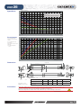
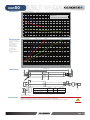
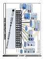
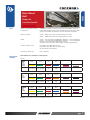
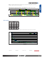
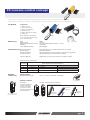
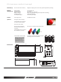
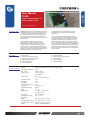
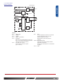
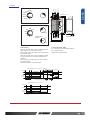
Elegance - in motion ATTUATORI CONCENS GB - excellent electric actuators Data Sheet con35 Linear In-line Actuator Data Motor 12/24 VDC power supply, permanent magnet motor Type (gear ratio) Maximum load Speed at maximum load con35 (5) con35 (14) con35 (19) con35 (27) con35 (51) con35 (71) [N] 120 400 600 900 1600 2200 [mm/s] 33 16 12 7.5 4 3 Recommended max. current: 12 VDC = 3.6 A / 24 VDC = 1.8 A Max. Static Load*)/ Self-locking force PA Brackets: 2000 N Alu Brackets: 5400 N *) Depending on stroke length for push-applications Temperature Operation: -5ºC to +70ºC Protection class IP66 Cable specification 1m, 2×0.25mm2 (AWG22), diameter ~ 4mm, black/grey Materials Motor and actuator tube Piston rod Front and rear brackets Powder coated steel Aluminium PA Duty cycle Max. 10% or 2 minutes in use followed by 18 min. rest Color Black (RAL 9005) is standard Storage: -40ºC to +70ºC Check for updates at www.concens.com Version 4.0 - June 2012 Check for updates at www.concens.com Stroke length/weight Stroke [mm] 50 100 150 200 250 300 350 400 500 750 Weight [kg] 0.8 0.9 1.0 1.1 1.2 1.3 1.4 1.6 1.8 2.3 Max. load limited to 1000 N for stroke lengths ≥ 500 mm. Actual weight may vary depending on model and options selected. Options *) On request Stainless steel versions (AISI 304 or AISI 316) Front and rear brackets in aluminium or stainless steel Front and rear brackets with clevis Brackets with spherical bearings Piston rod available in black (equivalent to RAL 9005) Hall sensors for positioning and/or synchronization IP68/IP69K (additional 11 mm to end-to-end dimensions, gear ratio 1:5 not available) *) Connector types (Molex 5557 / DIN 8 pole / Phono / Others) Low Noise ATEX zone 22, group II 3 D approval Certificate EN/UL/CSA 60.601 Eskimo version (-40ºC to +70ºC) Other cable lengths The dust and water sealing of IP68/69K actuators might affect their performance in lower gear ratios. Available in all RAL colors Other stroke lengths available Customised front, rear brackets and built in measures Contact Concens for any special requirements. pg. 1 con35 - excellent electric actuators Speed/force 1) Speed [mm/s] 22 20 Ratio 1:5 Load 120N, speed 33 mm/s 18 16 14 1:14 12 1:19 10 8 1:27 6 Check for updates at www.concens.com 20 1:51 4 1:71 2 0 0 200 400 600 800 1000 1200 1400 1600 1800 2000 2200 2400 Force/current Current [A] For 12 V DC power supply a factor 2. 3000 1:14 1:71 1:51 1:27 1:19 2 Use in the dashed area is not Please contact Concens for further 1.4 1) At ambient temperature T=25 ºC 117/127/137/148 +0,2 10 0 1.6 information. +0,2 10 0 1.8 recommended. 0 10 1400 1.0 mm +0,2 20 3000 10 +0,2 10 0 28 15 13 AISI 3xx Aluminium AISI 3xx PA 6.6 6,20 PA 6.6 28 6,20 6,2035 4,20 6,20 1.0 mm Aluminium AISI 3xx Aluminium 0 Axial backlash: 0.5 mm General dimension variation: PA 6.6 Aluminium AISI 3xx 10 4,20 28 28 13 15 +0,2 10 0 28 0 R1 4,20 2800 Length A 28 35 13 28 28 2600 Load [N] push / pull 10 7,5 PA 6.6 2400 117/127/137/148 1.0 mm R1 1.0 mm 2200 0 Axial backlash: 0.5 mm General dimension variation: Axial backlash: 0.5 mm General dimension variation: 2000 R1 Axial backlash: 0.5 mm General dimension variation: 10 1800 10 0 7,5 Dimensions 1600 13 Accuracy: ±10% 28 28 10 1200 4,20 1000 20 800 28 600 13 0 7,5 400 35 200 20 28 35 0 0 R1 28 117/127/137/148 10 +0,2 10 0 0 0.2 +0,2 10 0 35 10 0.4 R1 7,5 R1 117/127/137/148 +0,2 10 0 0.6 0 +0,2 10 0 7 R1 R1 117/127/137/148 ,50 0.8 +0,2 10 0 1.2 1 R1 2800 1) 2.2 multiply the current values with 2600 Load [N] push / pull Accuracy: ±10% Precautions Standard +10 +11 +10 Slash rear +10 +10 Hall +10 +10 +10 PA 6.6 Aluminium stroke length > 700 mm: + AISI 3xx 42 mm *s = stroke length stroke length > 500 mm: + 7 mm AISI 3xx PA 6.6 +10 +11 UL +11 +10 +11 +10 +11 stroke length > 700 mm: + 42 mm Power supply without over current-relay or other current switch-off devices can cause serious damage to the Build length A [mm] Standard Slash rear Hall UL IP68/IP69K actuator at mechanical end-stop or if the actuator is overloaded in another way. Gear ratio 5, 14, 19, 27 160 + s* +10 +10 +10 +11 Radial forces might have an adverse effect of the performance of, or lead to damage to the actuator. Gear ratio 51, 71 Concens A/S *s = stroke length Øresundsvej 7 170 + s* +10 stroke length > 500 mm: + 7 mm stroke length > 700 mm:T+ +45 42 mm70 +10 11 11 31 www.concens.com DK-6715 Esbjerg N F +45 76 10 50 10 [email protected] Denmark VAT: DK 10132266 +10 4,20 15 PA 6.6 IP68/IP69K 13 +10 UL 4,20 +10 IP68/IP69K 6,20 4,20 4,20 6,20 Build [mm] 160+s* +10 ratio 5, 14, +1019, Gear 27length A+11 160 + s* Gear ratio 51, 71 Gear ratio 5, 14, 19, 27 170+s* +10 +10 Gear ratio 51, 71 stroke length > 500 mm: 170++Aluminium 7s*mm * s = stroke length 6,20 +10 +10 Axial strokebacklash: length > 500±0.5 mm: + mm 7 mm stroke length > 700 mm: +variation: 42 mm General dimensional ±1 mm 28 160 + s* 170 + s* Hall PA 6.6 170 + s* 15 Slash rear +11 6,20 Aluminium +11 AISI 3xx +10 +10 13 +10 160 + s* 13 +11 +10 +10 PA 6.6 Aluminium AISI 3xx stroke length > 500 mm: + 7 mm 1.0 mm stroke length > 700 mm: + 42 mm Standard Clevis rear Hall Build length UL A [mm] IP68/IP69K 15 +10 +10 +10 6,20 *s = stroke length Standard UL +10 stroke length > 500 mm: + 7 mm Aluminium stroke length > 700 mm:51, + 42 Gear ratio 71mm AISI 3xx Axial backlash: 0.5 mm *s = stroke length General dimension variation: 4,20 Gear ratio 5, 14, 19, 27 Gear ratio 51, 71 *s = stroke length Aluminium AISI 3xx 28 Build length A [mm] Hall Gear ratio 5, 14, +10 19, 27 Standard IP68/IP69K +10+11 +10 170 + s* 6,20 4,20 PA 6.6 UL Slash rear 160 + s* Gear ratio 51, 71 Hall 28 Gear ratio 5, 14, 19, 27 Slash rear Build length A [mm] 28 28 28 Standard 28 10 Build length A [mm] +11 Concens partner: Specifications subject to change without prior notice. It is the responsibility of the product user to determine the suitability of Concens A/S products for a specific application. pg. 2 IP68/IP69K GB - excellent electric actuators Data Sheet con50 Linear In-line Actuator Data Motor 12/24 VDC power supply, permanent magnet motor Type (gear ratio) Maximum load Speed at maximum load con50 (4) con50 (14) con50 (17) con50 (24) con50 (49) con50 (84) [N] 500 1750 2200 3100 4500 4500 [mm/s] 70 20 17 12 6.0 4.0 Recommended max. current: 12 VDC = 16 A / 24 VDC = 8 A Max. Static Load*)/ Self-locking force PA Brackets: 4700 N Alu Brackets: 16800 N *) Depending on stroke length for push-applications Temperature Operation: -5ºC to +70ºC Protection class IP66 Cable specification 1m, 2×0.75mm2 (AWG18), diameter ~ 6mm, black/grey Materials Motor and actuator tube Piston rod Front and rear brackets Powder coated steel Stainless steel PA Duty cycle Max. 10% or 2 minutes in use followed by 18 min. rest Color Black (RAL 9005) is standard Storage: -40ºC to +70ºC Check for updates at www.concens.com Version 4.1 - November 2012 Check for updates at www.concens.com Stroke length/weight Stroke [mm] 50 100 150 200 250 300 350 400 500 750 Weight [kg] 2.1 2.3 2.6 2.8 3.1 3.3 3.6 3.8 4.3 5.6 Type con50 max. load limited to 2000 N for stroke lengths ≥ 500 mm. Actual weight may vary depending on model and options selected. Options *) On request Stainless steel versions (AISI 304 or AISI 316) Front and rear brackets in aluminium or stainless steel Front and rear brackets with clevis Brackets with spherical bearings Hall sensors for positioning and/or synchronization IP68/IP69K (additional 14 mm to end-to-end dimensions) *) Connector types (Molex 5557 / DIN 8 pole / Phono / Others) Low Noise ATEX zone 22, group II 3 D approval Certificate EN/UL/CSA 60.601 Eskimo version (-40ºC to +70ºC) Other cable lengths The dust and water sealing of IP68/69K actuators might affect their performance in lower gear ratios. Available in all RAL colors Other stroke lengths available Customised front, rear brackets and built in measures Contact Concens for any special requirements. pg. 3 con50 - excellent electric actuators Speed/force 1) Speed [mm/s] 30 28 Ratio 1:4 Load 500N, speed 70 mm/s 26 24 22 20 1:14 18 16 1:17 14 12 1:24 10 8 1:49 1:84 4 Check for updates at www.concens.com 6 2 0 0 500 1000 1500 2000 2500 3000 3500 4000 4500 5000 5500 6000 Accuracy: ±10% Force/current Current [A] 9.5 For 12 V DC power supply 1) 1:14 1:17 6500 7000 7500 8000 Load [N] push / pull 1:49 1:24 9 multiply the current values with a factor 2. 8.5 8 Use in the dashed area is not recommended. 7.5 Please contact Concens 1:84 7 for further information. 6.5 6 Max. 7A when used in connection with C3 5.5 system. 5 1) At ambient temperature 4.5 T=25 ºC 4 3.5 3 2,5 +0,2 16 0 175/190/205 +0,2 16 0 1 0.5 30 2 1.5 0 2500 3000 3500 4000 4500 5000 5500 6000 7000 7500 +0,2 16 0 40 Build length A 175/190/205 15 8000 Load [N] push / pull 5 +0,2 16 0 R 6500 R1 Dimensions 2000 175/190/205 25 30 1500 +0,2 16 0 1000 +0,2 30 16 0 500 50 0 Accuracy: ±10% 15 5 20 40 1.0 mm 20 40 40 40 15 +15 +14 255+s* Standard +15 +14 stroke length > 800240 mm: + s*+ 100 mm Gear ratio 49, 84 Axial backlash: ±0.5 mm General dimensional variation: ±1 mm 255 + s* *s = stroke length stroke length > 800 mm: + 100 mm Hall 20 240+s* Build length A [mm]49, 84) con50 (gearing 6,20 con50 (gearing 4, 14, 17, 24) * s Gear = stroke length ratio 4, 14, 17, 24 6,20 IP68 / 69K IP68/IP69K +15 +14 +15 +14 6,20 40 6,20 Hall 20 Standard 1.0 mm length A [mm] Build 40 Axial backlash: 0.5 mm General dimension variation: 6,20 1.0 mm 6,20 Axial backlash: 0.5 mm General dimension variation: Precautions 20 15 40 50 Axial backlash: 0.5 mm General dimension variation: 15 5 R1 15 20 5 R2 50 40 5 R1 R2 PowerBuild supply without over current-relay or other current switch-off devices can cause serious damage to the length A [mm] Standard Hall IP68/IP69K actuator at mechanical end-stop or if the actuator is overloaded in another way. Gear ratio 4, 14, 17, 24 240 + s* +15 +14 Radial forces might have an adverse effect of the performance of, or lead to damage to the actuator. Gear ratio 84 A [mm] Build49, length *s = stroke length 255 + Standard s* stroke length > 800 mm: + 100 mm Gear ratio 4, 14, 17, 24 Concens A/S Øresundsvej 7 240 + s*T Gear ratio 49, 84 www.concens.com DK-6715 Esbjerg N 255 + s* [email protected] Denmark *s = stroke length stroke length > 800 mm: + 100 mm +15 Hall +45 70 11 11 31 +15 F +45 76 10 50 10 +15 +14 IP68/IP69K +14 Concens partner: +14 VAT: DK 10132266 Specifications subject to change without prior notice. It is the responsibility of the product user to determine the suitability of Concens A/S products for a specific application. pg. 4 pg. 5 Standard: Con35 05 27 71 Special: con35 14 19 51 ’-’ = Standard ’+’ = Low Noise Product Series con50 14 17 49 con50 04 24 84 Standard: ’1' = 12Vf ’3' = 24Vf Special: ’4' = 24V ’5' = 36Vf ’6' = 36V Stroke Length Gearing Standard: ’2' = 2 mm std. nut (35) ’3' = 3 mm std. nut (50) Special: ’4' = 2 mm ”Slide Nut” (35) Low Noise Notes: 1) Values in bold are default values (used if nothing is specified) 2) Special requirements must be marked as ’x’ 3) Type ID equals ’00' for all standard actuators Standard: ’0050' = 50 mm ’0100' = 100 mm ’0200' = 200 mm ’0500' = 500 mm Special: ’0150' = 150 mm ’0250' = 250 mm ’0300' = 300 mm ’0350' = 350 mm ’0400' = 400 mm ’0750' = 750 mm ’1000' = 1000 mm Custom: ’xxxx' = xxxx mm ’35' = con35 ’50' = con50 ”Default” con50 -> ”Default” con35 -> Pitch Connector Hall Steel IP ’-’ = without hall sensor ’+’ = with hall sensor Cable length Standard: ’0' = Black cable, no connector (50) ’1' = Grey cable, no connector (35) Special: ’2' = Black cable, Molex Minifit connector ’3' = Grey cable, Molex Minifit connector ’4' = Black cable, DIN connector ’5' = Grey cable, DIN connector 1-9 m (default is 1 m) Voltage Tube Color Ring Color Standard: ’0' = Std. steel, IP66 Special: ’1' = AISI304, IP66 ’2' = AISI316, IP66 ’3' = AISI304, IP68 ’4' = AISI316, IP68 ’5' = AISI316, IP69K Standard: ’0' = PA ’2' = Alu Special: ’1' = PA with slash ’3' = Alu with slash ’4' = AISI316 ’5' = AISI316 with slash Brackets Standard: ’0' = Black Special: ’1' = Grey ’9' = Stainless steel 00-99 (00 = all standard) Rev08 – 19-aug-2008 – RL www.concens.com Standard: ’0' = Black, RAL9005, gloss 25 Special: ’1' = Grey, RAL9006, gloss 30 ’3' = White, RAL9003, gloss 70 ’9' = Stainless steel Type ID pg. 6 Stroke length is defined as the maximum length of movement the actuator can handle. Not to be mixed with ’built-in length’. Two series are available from concens: con35 & con50 The gearing of the actuator determines speed and maximum force. concens’ patented low noise option reduces the noise level considerably. Product Series Choose between 12, 24 or 36 volts. ’f’ (fast) motors have higher torque and speed, but is recommended for max 10% duty cycle. Stroke Length A Gearing C Cable length Hall Steel IP I Hall sensors are used to keep track of the position of the actuator. Cable/ Conn. concens actuators come with black or grey cable and are delivered without connectors as standard. Molex MiniFit or DIN connectors can be mounted for C3 system and Logic Data control boxes. Other special connectors can be mounted according to customer requirements. Cable length is measured ’end-toend’ i.e. including connector (if mounted). Special lengths are specified under Type ID Pitch D E F G H Voltage Standard pitch of lead screw is 2 mm for con35 and 3 mm for con50. However, 3 mm pitch is available for con35 upon request. Concens patented ’slide nut’ is availble for con35 (pitch = 2 mm). Low Noise B Tube Color Ring Color Tube material is painted standard steel (IP65) or stainless steel AISI304/ AISI316 (IP65, IP68 or IP69K). Front and rear brackets are available in PA, aluminum and stainless steel. They can be with or without slash (clevis). Special brackets can be made upon request Brackets J K L For IP65 actuators the piston ring (PA) can be black or grey. Rev02 – 09-oct-2008 – RL www.concens.com Standard steel actuators are delived with black motor- and actuator tube as standard. Other RAL colors are available on request. Type ID Type ID is used to specify special requirements. Standard actuators have type ID = 00 - excellent electric actuators Hall Data Sheet Hall Option for con35 and con50 Hall Hall Input/ Output Option for con35 and con50 Control Unit Possibility to precise control the start and end position of the actuator and the displacement during application. Furthermore, Hall gives the possibility to operate 2 or more actuators in parallel. Built-in measure con35 – additional 10 mm (see data sheet for con35) con50 – additional 15 mm (see data sheet for con50) Cable con35 - 1m, 8x0.14mm2 (6xAWG26), diameter ~ 5mm, black/grey con50 - 1m, 8x0.34mm2 (8xAWG22), diameter ~ 7mm, black/grey Maximum recommended cable length is 2.5 m Contact Concens for other cable lengths in special applications Concens control units C3 system (see data sheet for C3) Logic Data (see data sheet for Logic Data) C2-20 Concens servosystem Customer Control Unit PLC or likewise Check for updates on www.concens.com Version 3.2 - October 2010 Information for customer’s control unit: Wiring GREY Yellow Green Red Blue Hall A output open collector Hall B output open collector +5 V dc Hall 0V Hall Yellow Green Red Orange Function Hall A output open collector Hall B output open collector +5 V dc Hall 0V Hall BLACK Yellow Green Red Blue Function Hall A output open collector Hall B output open collector +5 V dc Hall 0V Hall Cable colour con35 con50 Function BLACK Cable colour con35 Brown+Pink White + Grey Actuator + Actuator - Brown Black Actuator + Actuator - Brown+Orange Black + Purple Actuator + Actuator - Cable colour con50 Warning: Power input in red wire must never exceed 5 V dc pg. 7 - excellent electric actuators Hall signal output yellow and green wire. 1/4 cycle delay between output sensor A and B. Order depends on displacement direction of the actuator. Output Sensor A 1 6 Output Sensor B 2 Hall Note: In a customer designed control unit external pull-up resistors from Hall signals to +5 V DC are necessary. Resistor values of 1 kΩ are preferred. 4 3 2 Check for updates on www.concens.com Output [v] Voltage[V] (V) Power 5 1 0 0 1 2 Time Pulse cycle [] Hall resolution C3 + con35 C3 + con50 Gear ratio mm/ pulse Gear ratio mm/ pulse 5 0.4 4 0.75 14 0.1429 14 0.2143 19 0.1053 17 0.1765 27 0.0741 24 0.1256 51 0.0392 49 0.0612 71 0.0282 84 0.0357 Note: Table shown for C3 controller. Resolution is 4 times better when using C2-20 servo controller. 0,75 0,7 con35 0,65 con50 Resolution [mm/Hall pulse] 0,6 0,55 0,5 0,45 0,4 0,35 0,3 0,25 0,2 0,15 0,1 0,05 4 6 8 10 12 14 16 18 20 22 24 26 28 30 32 34 36 38 40 42 44 46 48 50 52 54 56 58 60 62 64 66 68 70 72 74 76 78 80 82 84 0 Gearing [1:X] Concens A/S Øresundsvej 7 T +45 70 11 11 31 www.concens.com DK-6715 Esbjerg N F +45 76 10 50 10 [email protected] Denmark VAT: DK 10132266 Distributed by: Specifications subject to change without prior notice. It is the responsibility of the product user to determine the suitability of Concens A/S products for a specific application. pg. 8 C3 concens control concept The C3 system is a versatile solution for control of concens and other actuators. The unique design, strong power supply system and the option of controlling multiple actuators makes the C3 system attractive in various applications C3 System 2 1 Components 1. Battery (573 g) 2. Control box (491 g) 3. Remote control (93 g) 4. Bracket (318 g) 5. Battery charger box (500 g) 6. Safety clip 3 Black (RAL 9005) is standard colour and beige (Pantone 454) foil on remote control Battery (1) Type Power supply Maximum continuous current Capacity Low-capacity warning Control box (2) Number of remotes Connector type Number of outputs IP code standard 5 4 NiMH 24 V DC 7 A (Short-time peak current 10 - 20 A) 1400 mAh Sound signal 6 A C3 control box can recognize ID’s from max. 10 remotes Molex Mini-fit 5559 Up to 5 (4 actuators + 1 wired remote or emergency stop output) Standard IP50 (remark: IP65 available as option) Choice of different Adjusted by concens prior to delivery on customer request. Options for one control box No. of actuators Options (Both wired and wireless solutions) 1 1 Independent 2 2 Independent 2 Parallel 3 3 Independent 2 Parallel+ 1 independent 4 4 Independent 2×2 Parrallel 2 Parallel + 2 Independent Actuators running in parallel requires Hall (see Hall data sheet) Remote control (3) Wired solution Standard cable length 0.55 m - 2.30 m (retracted - extracted) Wireless solution Frequency 2.4 GHz communication frequency Two basic designs for location of buttons. Customer can select any button location and design from the two standard designs: Choice of black cord for eye in remote control. I Remote control battery cover Double hook suspensions II Single hook suspensions concens - ver 1.1 - 10 March 2008 - Check updates on www.concens.com or www.concens.eu Magnetic suspension ACTUATOR CONCEPTS pg. 9 C3 concens control concept Bracket (4) Part of control box delivery Magnetic coupling with control box (patent application pending) Battery charger (5) Power supply Charging time Mains connector Battery change Charging signal Full capacity signal 110 or 240 V AC 5 - 8 hours European / UK / US type Easy revolving fastening (patent application pending) Green light flashing Continous green light Patent Patent application PCT WO 2005/109563 Options Emergency stop on battery Customised colour and logo on foil for remote control Protection class IP 65 Emergency stop on battery Precise control of actuator movement and location of end stops. Hall sensor in actuator (see Hall data sheet) Customised colour of control box and battery charger Examples Customised remote design Customer can select any button location and design from three options: Multiple system design An unlimited number of control boxes can be setup identically and controlled by one remote control (only wireless). IV IV 54.5 40 156.2 7 Dimensions III 5 18 91.5 12 18 Battery Ø51.8 17 16.5 4 18 4 3 1 2 4 3.5 165 Battery Specifications subject to change without prior notice. It is the responsibility of the product user to determine the suitability of concens as products for a specific application. 45 Ø51.8 142 Remote control concens as Øresundsvej 7 DK-6715 Esbjerg N Denmark Phone: +45 70 11 11 31 Fax: +45 76 10 50 10 Mail: [email protected] Web: www.concens.com pg. 10 - excellent electric actuators C2-04 User Manual C2-04 Control and protection of linear actuator con35 introduction C2-04 is developed for controlled ON-OFF driving and direction change of the con35 actuator. C2-04 has advanced current limit features. It limits the motor current in start-up and jam-situations and in that way protects the motor and mechanics. C2-04 also has an error output indicating error/over current status. The acceleration ramp time for start-up is adjustable to suit each application. In other words the motor voltage is slowly rised to give a smooth start-up. When the control is off, the motor is dynamically braked with so called shortcircuit braking, i.e. the motor poles are connected together. The reverse and forward commands can be set with positive and negative control. features technical data Soft start-up Adjustable acceleration ramp Trip or continuous current limit Adjustable current limit Two control modes Freewheel option Supply Over voltage protection Idle current Driving current Current limit Current trip delay Start delay Stop delay Direction change time Voltage loss Operating frequency Ramp Digital inputs Error output Operating temp. (Ta) Dimensions: Board C2-04DIN (DIN version) C2-04BOX (box version) Weight Concens A/S Check for updates on www.concens.com Version 1.2 - September 2011 The freewheel command sets motor run free. Freewheel overrides forward and backwards commands. The current limitation is double acting. Firstly, there is a continuous and adjustable current limit, which decreases the motor voltage if the current exceeds the adjusted value. Secondly, there is settable trip feature that cuts the motor voltage if the current limit value is exceeded (after trip delay 2 ms). After trip the motor can only be started in the opposite direction. Additionally the C2-04 doubles the adjusted current value for 0.3 seconds during start-up to ensure sufficient power to overcome the start-up friction. Dynamic braking High momentary load capacity High efficiency Easy interfacing Rail base fittable 12-32 VDC (filtered, max. ripple <30% @ full load) 40 V Approx. 30 mA 2.7 A continuous 4.0 A 50/50% 0.5 ... 7 A 1.0 ... 14 A during start-up 2 ms 5 ms 5 ms 20 ms 0.5 V (Im = 4 A) 500 Hz 0.1 - 1 s “off” @ Uin 4-30 V or open “on” @ Uin 0-1 V Max. 30 V 50 mA -20 ... +70 ºC 73 x 43 x 25 mm (L x W x H) 90 x 46 x 56 mm (L x W x H) 102 x 73 x 47 mm (L x W x H) Approx. 40 g (Board alone) 1 pg. 11 c2-04 functional block diagram 8 5 7 Voltage reg - Forward Backwards 4 1 supply in driVe Control Mode freeWheel error control logic 3 poWer stage 10 Check for updates on www.concens.com 9 + 9V/ 10ma 6 C2-04 em-180 block diagramC2-04 Block Diagram m + 2 ramp . i-lim. trip . i meas. General Pin 1: Supply GND Pin 2: Actuator + Pin 3: Actuator Pin 4: Supply + (12-32VDC) Pin 5: Freewheel When this pin is pulled high, the motor runs free, i.e. as if it was electrically disconnected. This signal overwrites pin 8 and 9. Pin 6: 9V output; max. 10 mA. Can be used as source for inputs (pins 5, 8 and 9). Concens A/S Pin 7: Error This pin is pulled low when the current limit function is activated. This is an open collector output, max. 50 mA. External pull-up (10 K Ohm) may be required. Pin 8/9: Backward/Forward These pins are used to activate actuator backwards and forward. Please refer to description of “Control Mode” on page 3. Pin 10: GND 2 pg. 12 0 REVERSE ERROR 10ms 20ms 0 40ms 80ms 10ms 150ms 20ms 0 0.25s 0.5s 1s 40ms 80ms 150ms 6A 7A 0.25s 5A 0.5s 1s + 0V 10 9 FASTENING HOLES 3.2 mm 9V 8 7 6 C2-04 Factory settings FORWARD Start-up/ramp time FREEWHEEL settings 5 CONTROL MODE neg. pos. TRIP "off" "on" RAMP. con35 12VDC 3A 6A 7A 5A 2A 1A 0,4 A 4A + 7A 0,4 A 1 2 3 4 3A 23 mm + 2A 1A 0,4 A con35 24VDC 0V 7A 5 mm - DCMOTOR (default) Check for updates on www.concens.com Current 4Alimit value 66.5 mm 72.5 mm CURRENT +12-32V SUPPLY 5 mm FREE SPACE REQUIRED AT BOTTOM SIDE 37 mm + 43 mm 0,4 A FORWARD Control mode When put in mode “neg” is when a negativ (ground) signal is put on pin 8 and 9 to run motor. When using “neg” mode, then pin 10 can be used as the negative supply. When put in mode “pos” is when a positive (+)signal is put on pin 8 and 9 to run motor “backward” and “forward”. When using “pos” mode, then pin 6 can be used as the positive supply. Current for pin 8+9 is <1 mA when active. FORWARD no start-up to the same direction 5 CONTROL MODE neg. pos. after trip starts only to the opposite direction REVERSE TRIP "off" "on" I lim. =2 x set I lim = set MOTOR VOLTAGE RAMP. CURRENT 66.5 mm 72.5 mm motor brakes direction change motor brakes start-up cycle 300ms (ramp) 0-1s delay 20ms motor meets an obstacle current trip cuts the voltage OPERATION EXAMPLE: Continuous current limit FORWARD REVERSE 4 2-32V UPPLY Please refer to figures below. OPERATION EXAMPLE: Tripping current limit (recommended) no delay between the start-ups (same direction) FASTENING HOLES 3.2 mm V Current limit mode (TRIP) On = tripping limit (recommended, default) Off = continuous limit current limit x2 23 mm 5 mm 5 mm FREE SPACE REQUIRED AT BOTTOM SIDE Concens A/S I lim = set MOTOR VOLTAGE start-up cycle 300ms (ramp) 0-1s motor meets an obstacle driver limits the current 3 pg. 13 application info C2-04 PLC ERROR GROUND signal on C2-04 and control system (PLC) MUST be connected. Note: If distance between controller (e.g. PLC) and C2-04 is long or in area with a lot of electrical noise, use shielded cable. 0V 10 9 Analog or Digital output 8 7 6 5 CONTROL MODE neg. pos. Check for updates on www.concens.com TRIP "off" "on" Analog or Digital output RAMP. CURRENT 10 kohm Analog or Digital IN GND 1 2 + 3 4 - DCMOTOR 0V +12-32V SUPPLY Warnings and recommendations If C2-04 goes into “overcurrent” mode, it is only possible to run motor in opposite direction Please adjust the max. current level to be 10% higher than maximum current during running the actuator. This gives best conditions for long motor and actuator mechanical lifetime. It is very important to ensure that the power supply for the controller is capable of supplying sufficient current - otherwise the controller and/or the actuator may be damaged. Doublecheck correct polarity of power supply. If wrong connected, the C2-04 will be damaged. Attention! Driver has no fuse in it. Use external fuse according to application (1-4A). Concens A/S Øresundsvej 7 T +45 70 11 11 31 www.concens.com DK-6715 Esbjerg N F +45 76 10 50 10 [email protected] Denmark VAT: DK 10132266 Distributed by: Specifications subject to change without prior notice. It is the responsibility of the product user to determine the suitability of Concens A/S products for a specific application. pg. 14 - excellent electric actuators C2-15 User Manual C2-15 Control and protection of linear actuator con50 introduction C2-15 is developed for controlled ON-OFF driving and direction change of the con50 actuator. C2-15 has advanced current limit features. It limits the motor current in start-up and jam-situations and in that way protects the motor and mechanics. C2-15 also has an error output indicating error/over current status. The acceleration ramp time for start-up is adjustable to suit each application. In other words the motor voltage is slowly rised to give a smooth start-up. When the control is off, the motor is dynamically braked with so called shortcircuit braking, i.e. the motor poles are connected together. The reverse and forward commands can be set with positive and negative control. features technical data Soft start-up Adjustable acceleration ramp Trip or continuous current limit Adjustable current limit Two control modes Freewheel option Supply Over voltage protection Idle current Driving current Current limit Current trip delay Start delay Stop delay Direction change time Voltage loss Operating frequency Ramp Digital inputs Error output Operating temp. (Ta) Dimensions: Board C2-04DIN (DIN version) C2-04BOX (box version) Weight Concens A/S Check for updates on www.concens.com Version 1.2 - September 2011 The freewheel command sets motor run free. Freewheel overrides forward and backwards commands. The current limitation is double acting. Firstly, there is a continuous and adjustable current limit, which decreases the motor voltage if the current exceeds the adjusted value. Secondly, there is settable trip feature that cuts the motor voltage if the current limit value is exceeded (after trip delay 2 ms). After trip the motor can only be started in the opposite direction. Additionally the C2-15 doubles the adjusted current value for 0.3 seconds during start-up to ensure sufficient power to overcome the start-up friction. Dynamic braking High momentary load capacity High efficiency Easy interfacing Rail base fittable 12-32 VDC (filtered, max. ripple <30% @ full load) 40 V Approx. 30 mA 10 A continuous 15 A 50/50% 1 ... 21 A 2 ... 42 A during start-up 2 ms 5 ms 5 ms 20 ms 0.5 V (Im = 15 A) 500 Hz 0.1 - 1 s “off” @ Uin 4-30 V or open “on” @ Uin 0-1 V Max. 30 V 50 mA -20 ... +70 ºC 73 x 43 x 25 mm (L x W x H) 90 x 46 x 56 mm (L x W x H) 102 x 73 x 47 mm (L x W x H) Approx. 70 g (Board alone) 1 pg. 15 c2-15 functional block diagram 8 5 7 Voltage reg - Forward Backwards 4 1 supply in driVe Control Mode freeWheel error control logic 3 poWer stage 10 Check for updates on www.concens.com 9 + 9V/ 10ma 6 C2-15 em-180 block diagramC2-15 Block Diagram m + 2 ramp . i-lim. trip . i meas. General Pin 1: Supply GND Pin 2: Actuator + Pin 3: Actuator Pin 4: Supply + (12-32VDC) Pin 5: Freewheel When this pin is pulled high, the motor runs free, i.e. as if it was electrically disconnected. This signal overwrites pin 8 and 9. Pin 6: 9V output; max. 10 mA. Can be used as source for inputs (pins 5, 8 and 9). Concens A/S Pin 7: Error This pin is pulled low when the current limit function is activated. This is an open collector output, max. 50 mA. External pull-up (10 K Ohm) may be required. Pin 8/9: Backward/Forward These pins are used to activate actuator backwards and forward. Please refer to description of “Control Mode” on page 3. Pin 10: GND 2 pg. 16 0 REVERSE ERROR 10ms 20ms 0 40ms 80ms 10ms 150ms 20ms 0 0.25s 0.5s 1s 40ms 80ms 150ms 6A 7A 0.25s 5A 0.5s 1s + 0V 10 9 FASTENING HOLES 3.2 mm 9V 8 7 6 C2-15 Factory settings FORWARD Start-up/ramp time FREEWHEEL settings 5 CONTROL MODE neg. pos. TRIP "off" "on" RAMP. con50 12VDC 3A 18A 21A 15A 2A 1A 0,4 A 12A + 21A 0,4 A 1 2 3 4 8A 23 mm + 5A 3A 1A 0V 21A 5 mm - DCMOTOR con50 24VDC (default) Check for updates on www.concens.com Current 4Alimit value 66.5 mm 72.5 mm CURRENT +12-32V SUPPLY 5 mm FREE SPACE REQUIRED AT BOTTOM SIDE 37 mm + 43 mm 1A FORWARD Control mode When put in mode “neg” is when a negativ (ground) signal is put on pin 8 and 9 to run motor. When using “neg” mode, then pin 10 can be used as the negative supply. When put in mode “pos” is when a positive (+)signal is put on pin 8 and 9 to run motor “backward” and “forward”. When using “pos” mode, then pin 6 can be used as the positive supply. Current for pin 8+9 is <1 mA when active. FORWARD no start-up to the same direction 5 CONTROL MODE neg. pos. after trip starts only to the opposite direction REVERSE TRIP "off" "on" I lim. =2 x set I lim = set MOTOR VOLTAGE RAMP. CURRENT 66.5 mm 72.5 mm motor brakes direction change motor brakes start-up cycle 300ms (ramp) 0-1s delay 20ms motor meets an obstacle current trip cuts the voltage OPERATION EXAMPLE: Continuous current limit FORWARD REVERSE 4 12-32V UPPLY Please refer to figures below. OPERATION EXAMPLE: Tripping current limit (recommended) no delay between the start-ups (same direction) FASTENING HOLES 3.2 mm V Current limit mode (TRIP) On = tripping limit (recommended, default) Off = continuous limit current limit x2 23 mm 5 mm 5 mm FREE SPACE REQUIRED AT BOTTOM SIDE Concens A/S I lim = set MOTOR VOLTAGE start-up cycle 300ms (ramp) 0-1s motor meets an obstacle driver limits the current 3 pg. 17 application info C2-15 PLC ERROR GROUND signal on C2-15 and control system (PLC) MUST be connected. Note: If distance between controller (e.g. PLC) and C2-15 is long or in area with a lot of electrical noise, use shielded cable. 0V 10 9 Analog or Digital output 8 7 6 5 CONTROL MODE neg. pos. Check for updates on www.concens.com TRIP "off" "on" Analog or Digital output RAMP. CURRENT 10 kohm Analog or Digital IN GND 1 2 + 3 4 - DCMOTOR 0V +12-32V SUPPLY Warnings and recommendations If C2-15 goes into “overcurrent” mode, it is only possible to run motor in opposite direction Please adjust the max. current level to be 10% higher than maximum current during running the actuator. This gives best conditions for long motor and actuator mechanical lifetime. It is very important to ensure that the power supply for the controller is capable of supplying sufficient current - otherwise the controller and/or the actuator may be damaged. Doublecheck correct polarity of power supply. If wrong connected, the C2-15 will be damaged. Attention! Driver has no fuse in it. Use external fuse according to application (1-15A). Concens A/S Øresundsvej 7 T +45 70 11 11 31 www.concens.com DK-6715 Esbjerg N F +45 76 10 50 10 [email protected] Denmark VAT: DK 10132266 Distributed by: Specifications subject to change without prior notice. It is the responsibility of the product user to determine the suitability of Concens A/S products for a specific application. pg. 18 GB - excellent electric actuators DATA S H E E T C2-10 Control and protection of electric actuators C2-10 C2-10 is developed for controlled ON-OFF driving and direction change of the Concens actuators. C2-10 has advanced current limit features. It limits the actuator current in start-up, braking and jam-situations and in that way protects the motor and the mechanics. C2-10 also has a fault in- and output which indicates error/over-current status and can be used to stop the actuator (for example if an emergency-stop switch is used). The acceleration and deceleration ramp times are individually adjustable to suit each application. In other words the motor voltage is controlled to give a preferred smooth start and stop. When the C2-10 controller is without power, the motor is dynamically braked with so called short-circuit braking, i.e. the motor poles are connected together. The reverse and forward input can be set to work with negative or positive voltage by moving a jumper. C2-10 has a ‘trip’ feature that cuts the motor voltage if the current limit value is exceeded (after trip delay of 2ms). After trip the motor can only be started in the opposite direction. Additionally the C2-10 provides ‘kick-start’ which means 100ms at full power (100%PWM). Current limit during kickstart is up to 35A. If the actuator is stopped without going into trip mode, then the C2-10 controller will allow 50% higher current from start and until 500ms after ending acceleration ramp (see timing figure). Features Adjustable Soft start (acceleration ramp) Adjustable Soft stop (deceleration ramp) Adjustable current limit Two control modes High momentary load capacity High efficiency Easy interfacing to PLC etc. Connectors and terminals for actuators, control and power DIN-rail fittable Status LED Technical Data Supply 10-35 VDC (filtered max ripple <30%@full load) Over voltage protection 40 V Idle current Approx. 15 mA Driving current 10 A continuous, 16 A with duty cycle 50% Max 16 A on duty 2 min Current limit 0,5... 16 A Current trip delay 20 ms Start delay 5 ms Voltage loss 0,5 V (Im = 4A) Operating frequency 2000 hz Ramps 0,1 ... 2,5 s Digital inputs ‘High’ @ Uin 4 V → supply voltage, ‘Low’ @ Uin 0 V → 1 V Operating temp. (Ta) -20 ... +70 degC Kim Svane Brinch, manager for mechanical development, with the new Gerber Spreader XLs 125-spreader D ATA S H E E T | C2-10 | April 2013 vers. 1.0 | 1 pg. 19 DATA S H E E T - excellent electric actuators FIG. 1 W I R I N G FO R C2-10 General Fast blink: Current trip Four blinks: Overvoltage Solid light: Overtemp Current limit during start ramp and 500ms thereafter is current limit plus 50%. C2-10 Terminals LED signals: After trip the motor can only be started in the opposite direction. Additionally the C2-10 after trip provides ‘kickstart’, which means 100ms at full power (100%PWM). Current limit during kick-start is up to 35A. The fault terminal is both input and output (see fig. 2). During normal operation the signal is pulled high to 5 V on the C2-10 board in series with a 100k resistor. When a fault occurs the fault terminal changes to low voltage (GND via 100R resistor). FIG. 2 1 Supply GND 2 Supply + (10-35 VDC) fuse required 3 Actuator – 4 Actuator + 5 +5 V output for control-use max. 10 mA load 6 Fault in- and output 7 Reverse (Rev/In) signal input (0,5 mA) 8 Forward (Fwd/Out) signal input (0,5mA) 7+8 Used to activate the actuator back- and forward. Please refer to description of ‘Control mode’ on page 3 9 GND for control-use (not to be used as supply input) C I R C U IT D IAG RAM 2 | D A T A S H E E T | C2-10 | April 2013 vers. 1.0 pg. 20 DATA S H E E T - excellent electric actuators FIG.3 S E T T I N G S A N D M E C H A N I CA L D I M E N S I O N S Control mode When using ‘neg’ mode, then terminal 9 can be used as the negative supply. When jumper is put in mode ‘pos’ (jumper in right side) then a positive (> 4 V) signal is put on terminal 7 and 8 to run motor. FIG. 4 When using ‘pos’ mode, then terminal 5 can be used as the positive supply. NOTE: When using the connectors for remote control, then the jumper MUST be in ‘neg’ mode (left side). Input current for reverse & forward control is 0.5mA. T I M I N G D I AG R A M OPERATIONAL EXAMPLE OF CURRENT LIMIT, START/STOP RAMPS AND CONTROL INPUTS FAULT IN REVERSE no start-up to the same direction FORWARD I lim. =1.5 x set I lim = set MOTOR VOLTAGE start-up ramp 0-2.5s 500ms motor meets an obstacle current trip cuts the voltage after I-trip start only to the opposite direction stop ramp 0-2.5s start kick after I-trip 100ms current trip limit about 35A C2-10 When jumper is put in mode ‘neg’ (left hand side) then a negative (GND) signal is put on terminal 7 and 8 to run motor. I lim. =1.5 x set I lim = set MOTOR CURRENT D ATA S H E E T | C2-10 | April 2013 vers. 1.0 | 3 pg. 21 C2-10 DATA S H E E T www.concens.com - excellent electric actuators C2-10 (board alone) 73 x 43 x 25 mm (L x W x H) C2-10-DIN (DIN rail version) 90 x 46 x 56 mm (L x W x H) C2-10-BOX (box version) 102 x 73 x 47 mm (L x W x H) C2-10-BOX-XL (XL box version) 104 x 104 x 46 mm (L x W x H) Warnings and recommendations If C2-10 goes into “trip” (overcurrent), it is only possible to run actuator in opposite direction. Please adjust the max. current to be 10% higher than maximum current during running the actuator. This gives the best conditions for long motor and actuator mechanical and electrical lifetime. It is very important to ensure that the power supply for the controller is capable of supplying sufficient current – otherwise the controller and the actuator may be damaged. Doublecheck correct polarity of power supply. If wrong connected, the C2-10 will be damaged. Attention! Driver has no fuse in it. Use external fuse according to application ( 2 → 16A slow). Concens does not have any responsibility over the possible errors in this data sheet. Specifications are to be changed without notice. Concens A/S Øresundsvej 7 DK-6715 Esbjerg N Denmark T +45 70 11 11 31 F +45 76 10 50 10 E [email protected] VAT DK10132266 pg. 22 User Manual C2-20 ver 2,0 concens - ver 2.0 . - August 2010 - Check updates on www.concens.com or www.concens.eu 1 pg. 23 C2-20 User Manual C2-20 INTRODUCTION C2-20 is a full H-bridge DC-motor controller. It is designed to work with con35 and con50 electrical in-line actuators in applications where some special functions are needed. It is also possible to use this device with actuators that gives pulses with hall sensors. C2-20 has adjustable acceleration and deceleration ramps, which make the smooth starts and stops possible . Adjustable current limits in both directions protects motor against FEATURES • • • • • • • • • • TECHNICAL DATA overcurrent and it can also be used as an endstop. This device has also two adjustable speeds, whereas the 2nd is used in the learning mode to count the number of hall pulses in a full stroke of the actuator. This enables an accurate positioning of the actuator so it is working as a servo. Control input is a voltage. The stroke of the actuator is controlled by sending a DC voltage between 0-10,0 Volt to the C2-20. Adjustments and settings: Adjustments and parameter setting like current limit value, ramp times, speed-2 value and all other needed parameters can be set with C2-PROG interface unit, or USB cable with a “dongle” connected to a PC or LAPTOP. This enables the accurate copying of settings and reliable operation of the device in demanding environment. See page 2 for more details. Fast change of direction Soft start-up, acceleration ramp Settable current limit Trip or continuous current limit High efficiency Dynamic braking High momentary load capacity Rail base fittable Freewheel option Two control modes Supply voltage 9-35VDC Actuator current continuous max 15A ( Ta<60°C ) Actuator current max 20A (short time) Current limit adj. 0.1-20A Overheat limit 110°C PWM frequency 2kHz Hall input freq. max 1khz Input control logic: “pos” ON=4-30V, OFF=0-1V or open Control input impedances typ. Motor and supply connectors: Control connectors: Dimensions Dimensions in DIN-rail base 30kohm 2.5mm wires max 1mm wires max 42x72x25mm 45x80x45mm CE-tested for industrial enviroment ( EMC ) Weight 75g Operating temp ( Ta ) 0-60°C 2 concens - ver 2.0 . - August 2010 - Check updates on www.concens.com or www.concens.eu pg. 24 Recomended ripple lower than 20 %. DC First run the learning cycle and then do the settings with serial interface unit “C2-PROG” or PC or LAPTOP 1/15 Speed - 35 - 100% <=> 35-100 ( 100 ) 2/15 Learning speed - 35 - 100% <=> 35-100 ( 50 ) 3/15 I-limit “out” 0,1 - 20,0A <=> 1-200 ( 20 ) 4/15 I-limit “in” 0,1 - 20,0A <=> 1-200 ( 20 ) Notice! current limits are 1.5 times higher during start ramp. 5/15 I-trip enable 6/15 I-trip delay 0 - 255ms <=> 0 - 255 ( 5 ) 7/15 Load compensation 0 -255 <=> 0 - 255 ( 0 ) 8/15 Pulse lost timeout 1 - 5s <=> 1 - 5 ( 2 ) 9/15 Start value 0 - 50% <=> 0 - 50 ( 30 ) 10/15 Hour/Start count reset 0 - 1, reset when set to 1 11/15 Brake area 0,0 - 20,0% <=> 0 - 200 (50) 12/15 Dead zone 0,0 - 10,0% <=> 0 - 100 (10) 13/15 Range scale in + 0,0 - 50,0% <=> 0 - 500 ( 7 ) 14/15 Range scale out - 0,0 - 50,0% <=> 0 - 500 (70) 15/15 Start ramp 0,1 - 5s <=> 0 - 500 ( 100 ) C2-20 C2-20 WIRING AND SETTINGS FOR C - Speed setting limits the maximum speed. - Learning speed sets the learning cycle speed. ( pict. 2 ) - I-limits are individual for in and out directions - I-trip enables the trip function, so that motor will be shut down when the set I-lim is exceeded. - I-trip - Load compensation increases the torque at low speed. Notice that over compensation will cause oscillation and twiching of the motor. - Pulse lost time-out stops motor after the set time without pulses. - Brake area is proportional value of the full stroke. In low speed application good value is near 1%, and in high speed solution it can be near to 20% ( pict. 1 ) - Dead zone is steady area, suitable size of this zone depends on the mechanical accuracy of the system, this value is also a ratio of the full stroke (%) ( pict 1. ) - Start value is a voltage level for start (% of full), this ensures that the motor gets an adequate voltage to start properly, but notice that too high start level will cause motor vibration (pict 1). - Range scale adjustment is for scaling of the stroke, with this can the scale be adjusted after learning. The in and out ends are individually scaleable to get the suitable mechanical stroke for set value from 0-5V ( pict. 3 ) - Hour/Start count reset makes possible to set the hour/start counter to zero - Start ramp limits the acceleration speed when motor starts. concens - ver 2.0 . - August 2010 - Check updates on www.concens.com or www.concens.eu 3 pg. 25 WIRING AND SETTINGS FOR C2-20 ver 2,0 menu select save + TERMINALS: PC or LAPTOP - +5,4V - voltage output, max 10mA FAULT IN/OUT- pnp open collector max 100mA can be connected to other C2-20 modules, thereby all modules connected will stop if one module sends a FAULT signal. If wirelength is more than 1 meter, a 10kohm pull-up resistor connected to supply is recommended. POS. SET - analog input 0-10V (0-5V if SW1 on 4 pole SW is OFF), Rin 30k STOP/RESET - digital in. (>4V and max supplyvoltage) Rin 47k. Stops the motor and resets any fault. LEARNING - digital in. (>4V and max supplyvoltage) Rin 47k, starts “learning”. POSITION OK - digital out 5 Volt through 1kohm when wanted position is reached, and low during movement. Note: if “Brake Zone” is very long, then POSITION OK signal can be difficult to reach, since the motor only gets very low power to reach within the “dead zone”. GND - signal gnd, same potential as terminal 4. USB GND STOP/ RESET POSITION IN 0-10V (0-5V) LEARNING 9 +5,4 V POSITION OK 8 FAULT IN/OUT dongle C2-USB 10 11 12 13 14 fault indication led 66 on 1 2 3 4 DIPsw Cables: 36 42 con35 cable Black Grey 1 Hall + red red 2 Hall A yellow yellow 3 Hall B green green 4 Hall GND orange blue 5 Actuator - black white/grey 6 Actuator + brown bwn/pur off 72 C2-20 C2-PROG PARAMETER SET HEIGHT 25mm con50 cable Black Grey red yellow green blue blk/pur bwn/or red yellow green blue white/grey bwn/pur LED blinking signals 1 2 3 4 5 6 7 I-limit occurs = fast blinking Overtemp = slow blinking Pulse lost = short, mid, long, short mid long... Over voltage = burst - pause etc. +5.4V +9 - 35V + picture 1 "positioning window" GND (0V) brake area start ramp dead zone H H 5 6 ACTUATOR CONCENS 35/50 WITH HALL SENSOR. M start level from old position 0V in=0% picture 2 "learning cycle" 10V out=100% 4. 5. 2. 3. setted position 2 3 4 motor speed 1 to new position picture 3 "range scaling" range adj. out -20% out=100% out=80% range adj. in +20% in=20 in=0% 1. 6. 1. 1. start learning by giving an impulse to learn input (10) 2. motor starts to run “out” direction with learn speed 3. current limit stops the motor when mechanical end is reached 4. motor starts to “in” direction and makes a full stroke. During stroke the pulse counter measures the range. 5. motor reaches the mechanical end “in”, and current limit stops the motor. 6. Device stores full range value and is ready for use Specifications subject to change without prior notice. It is the responsibility of the product user to determine the suitability of concens as products for a specific application. 4 2. 0V 10V (5V) -20% +20% 0V 10V (5V) 1. original learned range = mechanical full range equals the signal range 0-10V If range scale in = +20% and range scale out = -20%. now stroke of actuator is compressed to: positioning set value 0V = 20% position positioning set value 10V (5V) = 80% position concens as Øresundsvej 7 DK-6715 Esbjerg N Denmark Phone: +45 70 11 11 31 Fax: +45 76 10 50 10 Mail: [email protected] Web: www.concens.com concens - ver 2,0 - August 2010 - Check updates on www.concens.com or www.concens.eu pg. 26 1 8 2 7 3 6 4 5 pg. 27 www.setec-group.it www.setec-group.it TORINO TORINO Direzione Generale - Headquarter: Direzione Generale eVia Stabilimento Produzione - Headquarter and Production Plant: Mappano,di17 - 10071 Borgaro T.se (TO) Via Mappano, 17 10071 Borgaro T.se (TO) TORINO T +39 011 451 8611 (centr. r.a.) - F +39 011 470 4891 TORINO T +39 011 451Direzione 8611 (centr. r.a.) - F +39 011 470 4891 Direzione Generale Headquarter: [email protected] Generale -- Headquarter: [email protected] Via Mappano, 17 10071 Borgaro T.se (TO) (TO) Via Mappano, 17 - 10071 Borgaro T.se +39 011 011 451 451 8611 8611 (centr. (centr. r.a.) r.a.) -- FF +39 +39 011 011 470 470 4891 4891 TT +39 [email protected] [email protected] HIWIN HIWINGW GWENG HIWIN ENGREV02 REV02 GW ENG REV02 MILANO Via Meccanica, 5 MILANO 20026 Novate (MI)5 - Z. I. Vialba Via Meccanica, T +39 02 356 0990 - 382 01 590 (r.a.) MILANO 20026 Novate (MI) Vialba MILANO F Via +39 02- Z. 356I. 0943 Meccanica, 5 Via-Meccanica, 5 (r.a.) T +39 02 356 0990 382 01- Z. 590 [email protected] 20026 Novate (MI) I. Vialba Vialba 20026 Novate (MI) Z. I. F +39 02 356 0943 TT +39 +39 02 356 0990 382 01 590 (r.a.) (r.a.) 02 356 0990 - 382 01 590 [email protected] +39PADOVA 02 356 356 0943 0943 FF +39 02 Via Secchi, 81 [email protected] [email protected] 35136 Padova PADOVA +39 PADOVA 04981 872 5983 ViaFT Secchi, PADOVA +39 049 856 0965 Via Secchi, 81 81 Via Secchi, 35136 Padova [email protected] 35136 Padova 35136 Padova T +39 049 872 5983 - F049 +39 049 856 0965 +39 872 5983 TT +39 049 872 5983 [email protected] +39 049 049 856 856 0965 0965 FF +39 [email protected] [email protected] BOLOGNA Via Del Lavoro, 6/A BOLOGNA 40051 Altedo (BO) Via Del Lavoro, 6/A T +39 051 BOLOGNA 871 949 (3 linee r.a.) 40051 Altedo (BO) BOLOGNA F +39 051 870 329 Via Del Lavoro, 6/A Via Del Lavoro, 6/A [email protected] +39 051Altedo 871 949 40051 (BO) (3 linee r.a.) 40051 Altedo (BO) F +39 051 870 r.a.) 329 +39 051 051 871 871 949 949 (3 (3 linee linee TT +39 r.a.) FIRENZE FF +39 +39 051 870 329 [email protected] 051 870 3293 Via Galileo Galilei, [email protected] [email protected] 50015 Bagno a Ripoli - Grassina (FI) FIRENZE T +39FIRENZE 055 643 261 Via Galileo Galilei, 3 FIRENZE F +39 055 646 6614 Via Galileo Galilei, 3 Via Galileo Galilei, 3 50015 Bagno a Ripoli - Grassina (FI) 50015 [email protected] Bagno a a Ripoli Ripoli -- Grassina Grassina (FI) 50015 Bagno (FI) T +39 055 643 261 F +39 055 646 6614 +39 055 643- 261 261 TT +39 055 643 FF +39 +39 055 646 6614 [email protected] 055 646 6614 [email protected] [email protected] www.setec-group.it www.setec-group.it Distribuito da / Distributed by: