1
SMT356
User Manual
User Manual (QCF42); Version 3.0, 8/11/00; © Sundance Multiprocessor Technology Ltd. 1999
Version 2.1
Page 2 of 26
SMT356356 User Manual
Revision History
Date
Comments
Engineer
Issue
19/9/2000
First draft
GKP
1.0
21/9/2000
Second draft
GKP
1.1
30/4/2001
Converted to new form and added spectrum
GKP
2.0
22/2/2005
Clarified JP1 function
GKP
2.1
The SMT356 is a size 1 TIM offering the following features;Four communications ports for control
8 channel, 14-bit simultaneous sample ADC
High bandwidth data output via a single 16-bit SDB (Sundance Digital Bus)
Notes:
Within the drawings, DIP Switch refers to Jumper Bank 1.
Version 2.1
Page 3 of 26
SMT356356 User Manual
Table of Contents
Revision History.......................................................................................................... 2
Notes: ......................................................................................................................... 2
Table of Contents ....................................................................................................... 3
Architecture Description ............................................................................................. 4
EMC ........................................................................................................................... 5
Power ......................................................................................................................... 5
ADC Sub-System ....................................................................................................... 6
Input Level .................................................................................................................. 6
Output Codes ............................................................................................................. 6
ADC Control ............................................................................................................... 7
Programmable Clock Divider ...................................................................................... 8
Sample Clock Routing .............................................................................................. 10
Connector Position ................................................................................................... 11
Jumper Bank JP1.................................................................................................. 11
Input Circuitry ........................................................................................................... 12
Virtex ........................................................................................................................ 13
SDB .......................................................................................................................... 13
SDB Pin-Out ............................................................................................................. 14
Clock Enable ............................................................................................................ 16
Clock Source ............................................................................................................ 16
Example Code .......................................................................................................... 18
Configure Virtex .................................................................................................... 18
General Operation Description.............................................................................. 21
Spectrum (typical)..................................................................................................... 26
Version 2.1
Page 4 of 26
SMT356356 User Manual
Architecture Description
The SMT356 (356) module is a single width TIM device.
It incorporates a Xilinx XCV300 Virtex FPGA.
Eight 14-bit ADCs interface to the Virtex device, together with six ‘C40 style comm
ports.
Version 2.1
Page 5 of 26
SMT356356 User Manual
EMC
This module is designed to operate from within an enclosed host system, which is
built to provide EMC shielding. Operation within the EU EMC guidelines is not
guaranteed unless it is installed within an adequate host system.
This module is protected from damage by fast voltage transients originating from
outside the host system which may be introduced through the output cables.
Short circuiting any output to ground does not cause the host PC system to lock up
or reboot.
Power
This module must be fixed to a TIM40 compliant carrier board. Additionally, a 3v3
power source must be provided to the fixings. This is normally achieved by means of
a power source provided directly through conducting pillars on the carrier board.
Power for the analog components on this module is provided by on-board dc-dc
converters. All of the analog circuitry is shielded on the top and bottom of the module
using custom RFI shielding cans.
Version 2.1
Page 6 of 26
SMT356356 User Manual
ADC Sub-System
This consists of 8 Analog Devices AD9240 converters. These provide an overall
system performance with an ENOB of 12 (minimum) for each of the eight channels.
All ADCs simultaneously sample using the same clock.
Input Level
The input to the ADC module is DC coupled with a pk-pk level of 2v. This is centred
about 0v.
Vmin=-1v
Vmax=+1v.
Output Codes
The converted samples are presented on the SDB connector as 16 bit offset binary.
Code 0x0000 is equivalent to –Vmax
Code 0x8000 is equivalent to 0V
Code 0xFFFC is equivalent to +Vmax
The two least significant bits of the output word are undefined and should be masked
by the user.
Version 2.1
Page 7 of 26
SMT356356 User Manual
ADC Control
All of the ADCs are controlled via one of the six available ‘C40 style comm ports. The
desired comm port must be selected using the jumper bank JP1.
JP1 – positions 5-7
Comm Port
7
6
5
ON
ON
ON
0
ON
ON
OFF
1
ON
OFF
ON
2
ON
OFF
OFF
3
OFF
ON
ON
4
OFF
ON
OFF
5
This interface contains a single control register. This controls the clock divider, clock
enable, ADC enable and the state of the four LEDs. This register is described here,
Control Register
Data Bits
Function
D7-0
Clock Divider
D15-8
ADC Enable
D19-16
LED4-1 control
D20
Clock enable
D21
Clock enable mode
D22
SDB mode
D23
Reset FIFO
D31-24
Sample count
Bit D20 of this register controls the ADC clock enable via software. A ‘1’ enables the
ADC, or generates a rising edge trigger (depending on clock enable mode). The
power-on state of this bit is ‘0’.
Bit D21 controls the clock enable mode. A ‘0’ selects latched counter mode, a ‘1’
selects direct control. The power-on state of this bit is ‘0’.
Version 2.1
Page 8 of 26
SMT356356 User Manual
D31-24 determines the number of samples in clock enable mode ‘0’. The range is
from 1-256. The value loaded into bits 31-24 is the required sample count –1. A value
of 0 gives 1 sample, a value of 0xFF gives 256 samples.
Note that the sample count should be changed before the acquisition is triggered.
Bits D15-8 control the enabled state of the 8 ADCs. The power-on state is a ‘1’ for
each bit, indicating that all channels are enabled. Setting a bit to a ‘0’ will remove that
ADC’s output from appearing in the SDB data stream.
Programmable Clock Divider
An 8-bit divider is provided which allows the ADC clock to be provided from a divided
clock. The following table shows the possible values,
Divider Value
ADC Sample
Frequency (MHz)
Division
[External clock]
[Internal clock]
00
50
2
01
25
4
02
16.6
6
03
12.5
8
04
10
10
05
8.3
12
06
7.1
14
07
6.3
16
08
5.5
18
09
5
20
…
Sampling rates of 50, 25, 16.6 and 12.5 are not allowed.
Version 2.1
Page 9 of 26
SMT356356 User Manual
The divider can be bypassed in order to get a division of 1. This is achieved as
follows,
JP1 – position 3
OFF
ON
Divider bypass
Divider enable
Note that selecting divider bypass is not compatible with using the
internal clock as this would attempt to clock the ADCs at 100MHz.
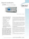
The programmable divider power on default setting is to divide by 2.
100MHz
OSCILLATOR
EXTERNAL 0-10MHz
SAMPLE CLOCK
DIV BY 2
DIP Switch
1
MUX
DIP Switch
4
MUX
PROGRAMMABLE
DIVIDER
SDB CLOCK
DIP Switch
3
MUX
TOADCs
SAMPLE CLOCK
OUTPUT
Version 2.1
Page 10 of 26
SMT356356 User Manual
Sample Clock Routing
Version 2.1
Connector Position
Jumper Bank JP1
Page 11 of 26
SMT356356 User Manual
Version 2.1
Input Circuitry
Page 12 of 26
SMT356356 User Manual
Version 2.1
Page 13 of 26
SMT356356 User Manual
Virtex
The main component which controls the operation of the module is a Virtex FPGA
from Xilinx. This device is volatile in nature, and requires reconfiguring every time the
module is powered on. The configuration data (bitstream) must be presented through
comm port 3.
The bitstream is supplied on the distribution disk as ‘smt356.mcs’. This is an ASCII
text file and a function for configuring is supplied. This function makes use of stdio file
operations.
When this module is used with a TIM with large flash memory, then the configuration
can be stored in this memory and this operation is therefore much faster. Eg. The
SMT332 may be ordered with the 356 configuration in flash memory and a simpler
function is used to configure the Virtex.
When the module is not configured, LED5 will be illuminated. Upon successful
configuration, LED5 will extinguish.
SDB
The sampled data is output on an SDB (Sundance Digital Bus) connector. This is
simple yet versatile bus system, with a protocol for bi-directional data transfer. The
SDB implementation on this module is as an output only.
Once the sample clock is enabled, all ADCs are sampled at the same time at a
frequency selected by Jumper Bank position 1 and/or the divider.
The 14 bit samples occupy the higher 14 bits of the SDB word. Bits 0 and 1 are
undefined.
The sampled data is presented, one channel at a time, to the most significant 14 data
bits of the SDB connector. This data will be transmitted on the SDB as a packet with
the WEN signal active (low) for the whole packet.
The sample data is buffered within a 256 word FIFO.
Version 2.1
Page 14 of 26
SMT356356 User Manual
SDB Pin-Out
Pin
Signal
Signal
Pin
1
CLK
GND
2
3
D0
GND
4
5
D1
GND
6
7
D2
GND
8
9
D3
GND
10
11
D4
GND
12
13
D5
GND
14
15
D6
GND
16
17
D7
GND
18
19
D8
GND
20
21
D9
GND
22
23
D10
GND
24
25
D11
GND
26
27
D12
GND
28
29
D13
GND
30
31
D14
GND
32
33
D15
GND
34
35
UD0
DIR
36
37
WEN
REQ
38
39
UD1
ACK
40
Version 2.1
Page 15 of 26
SMT356356 User Manual
The maximum sampling rate per ADC is 10MHz, which indicates that the maximum
SDB word rate would be 80MHz. The SMT356 module allows for the SDB word rate
to be set to either 50 or 100MHz as follows,
JP1 – position 4
OFF
ON
SDB=100MHz
SDB=50MHz
A lower word rate may be needed where the receiving device is not able to sustain
the faster transfer speed.
If the sampled data rate (number of channels enabled x sample rate) is in excess of
the SDB data rate (50 or 100MHz), then the module’s internal FIFO will fill up. When
the FIFO has become full, LED1 will illuminate but the module will still process data.
The LED will remain illuminated until a control word with bit D23 set is received. Note
that this bit needs to be cleared before proper operation can be resumed.
At a sample rate of 5MHz with all channels enabled, the standard 50MHz SDB data
rate is sufficient to operate without FIFO filling problems.
Notes:
The SDB bi-directional functionality is not supported on this module.
The ACK signal on the SDB connector is not used.
The user defined pin UD0 is not used, UD1 is driven high (when connected to
an SMT332, UD1 is the FIFO partial reset).
The write enable pin (WEN) is driven active (low) by the SMT356 when it is
transmitting data on the SDB.
Version 2.1
Page 16 of 26
SMT356356 User Manual
Clock Enable
The clock enable (ADC sample enable) is controlled from either the external enable
input or from an enable register. The selection is made as follows,
JP1 – position 2
OFF
ON
External enable
Internal enable
register
The external enable input has a pull-up resistor to the active state. So, if the module
was to be permanently enabled, then Jumper Bank-2 should be in the ON position
and the clock enable input left unconnected.
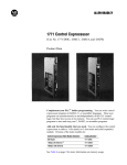
The clock enable mode is selected by bit D21 of the control register. With this bit set
to ‘0’, the external clock enable rising edge is used to start a counter which in turn
allows the ADC to be enabled for a pre-set number of samples. The sample count is
set in the control register bits D31-24. If control register bit D21 is set to '1’, then the
external clock enable is routed directly to the ADC and samples will therefore be
taken so long as this signal remains active (‘1’). This is shown diagrammatically in the
following figure.
Clock Source
The sample rate of the converters is derived from one of two sources. Either from an
external clock input or via the on-module reference. The selection is made as follows,
JP1 – position 1
OFF
ON
External clock
Internal clock
The maximum external clock frequency is 10MHz. This should be TTL compatible.
In either mode, the selected clock is passed through a programmable divider and
then output to a connector.
DIP Switch
2
MUX
START
VALUE
COUNTER
ENABLE
SAMPLE
COUNTER
LATCH
Control Register
bit D21
MUX
CLOCK ENABLE
FOR ADCs
Page 17 of 26
SAMPLE CLOCK
Control Register
bits D31-24
Control Register
bit D20
EXTERNAL CLOCK
ENABLE INPUT
Version 2.1
SMT356356 User Manual
Version 2.1
Page 18 of 26
Example Code
Configure Virtex
(included in file scope356.c)
Open Virtex configuration file
if (!( fp = fopen("smt356.mcs","rb") )) {
printf("Could not open smt356.mcs file.\n");
exit(0);
}
Read configuration file until the end
while (not_end) {
// read start character ':'
ch=fgetcc(fp);
// read byte count
byte_count =hex2dec(fgetcc(fp))<<4;
byte_count+=hex2dec(fgetcc(fp));
// read address
address =hex2dec(fgetcc(fp))<<12;
address+=hex2dec(fgetcc(fp))<<8;
address+=hex2dec(fgetcc(fp))<<4;
address+=hex2dec(fgetcc(fp));
// read record type
record_type =hex2dec(fgetcc(fp))<<4;
record_type+=hex2dec(fgetcc(fp));
record_decoded=0;
SMT356356 User Manual
Version 2.1
Page 19 of 26
SMT356356 User Manual
Decode record type
if (record_type==1) {
not_end=0;
// end of file
record_decoded=1;
}
if (record_type==2) {
// extended address
record_decoded=1;
load_address =hex2dec(fgetcc(fp))<<12;
load_address+=hex2dec(fgetcc(fp))<<8;
load_address+=hex2dec(fgetcc(fp))<<4;
load_address+=hex2dec(fgetcc(fp)); // read load address
load_address<<=4;
printf("Address:%08X\n",load_address);
}
if (record_type==4) {
// extended address
record_decoded=1;
load_address =hex2dec(fgetcc(fp))<<12;
load_address+=hex2dec(fgetcc(fp))<<8;
load_address+=hex2dec(fgetcc(fp))<<4;
load_address+=hex2dec(fgetcc(fp)); // read load address
load_address<<=16;
printf("Address:%08X\n",load_address);
}
address+=load_address;
// add address offset
Version 2.1
Page 20 of 26
if (record_type==0) {
SMT356356 User Manual
// data record
record_decoded=1;
for(i=0;i<(byte_count/4);i++) {
load_word =hex2dec(fgetcc(fp))<<4;
load_word+=hex2dec(fgetcc(fp))<<0;
load_word+=hex2dec(fgetcc(fp))<<12;
load_word+=hex2dec(fgetcc(fp))<<8;
load_word+=hex2dec(fgetcc(fp))<<20;
load_word+=hex2dec(fgetcc(fp))<<16;
load_word+=hex2dec(fgetcc(fp))<<28;
load_word+=hex2dec(fgetcc(fp))<<24;
bytes_read+=4;
// Send config word to SMT356 comm port 3
comm_out(load_word);
}
}
if (record_decoded==0) {
printf("\n\nERROR - invalid record type: %X\n",
record_type);
while(1);
}
ch=fgetcc(fp);
// read checksum
ch=fgetcc(fp);
ch=fgetcc(fp);
ch=fgetcc(fp);
}
printf("Done\n%X\n",bytes_read);
// read cr-lf
Version 2.1
Page 21 of 26
SMT356356 User Manual
General Operation Description
(Included as file qwikscope356.c)
This little application runs under SMT6000. It demonstrates the quick method to
configure the Virtex from flash memory on the SMT332. The application displays all 8
channels in an oscilloscope type display on the SMT6000 graphical window.
Include this because we are going to do printf.
#include <stdio.h>
volatile unsigned int *comm_status, *comm0_data;
This is a function which converts an ASCII hex character into binary.
unsigned char hex2dec(unsigned char hexnum)
{
if(hexnum<0x3a) return(hexnum-0x30);
else return(hexnum-0x37);
}
This function outputs to comm port 0.
void comm_out(unsigned int d)
{
while( ((*comm_status) & 2) == 0 )
printf("waiting for comm out rdy\n");
*comm0_data=d;
}
this function waits for data input on comm port 0.
unsigned int comm_in()
{
while( ((*comm_status) & 1) == 0 )
printf("waiting for comm in rdy\n");
return(*comm0_data);
}
Version 2.1
Page 22 of 26
SMT356356 User Manual
main()
{
volatile unsigned int *flash, delay;
volatile unsigned int i, j, b, pass, y, byte, load_word;
volatile unsigned *fifobase, *emifce3, *flags, temp,
flagpos, ctrl_word;
unsigned samples,leds,channels,divider,active_channels;
volatile char ch;
Point to comm port status register,
comm_status=(unsigned int *)0x01600010;
and to data register.
comm0_data =(unsigned int *)0x01600000;
We will have to change the ‘C60’s EMIF to change the memory type on memory
space CE3.
emifce3=(unsigned *)0x01800014;
This is where the FIFO flags are on the SMT332.
flags=(unsigned *)0x01580000;
And this is where the FIFO hangs out.
fifobase=(unsigned *)0x03800000;
This is the quick way to configure the SMT356’s Virtex.
printf("Configuring 356 from flash\n");
This address is defined by Sundance, and is where the configuration is stored.
flash
=(unsigned *)0x01424000;
for(i=0;i!=0x35758/4;i++) {
Read the flash. Don’t forget to mask with 0xFF because the flash device only drives
the lower 8 bits, but is still accessed as a 32 bit word!
load_word=
(*flash++)&0xff;
load_word+=((*flash++)&0xff)<<8;
load_word+=((*flash++)&0xff)<<16;
load_word+=((*flash++)&0xff)<<24;
comm_out(load_word);
}
printf("%08X done\n\n",flash);
Version 2.1
Page 23 of 26
SMT356356 User Manual
This bit is necessary to ensure that the hardware of the SMT332 is in a known good
state.
// set mux signal to known state
for(i=0;i!=16;i++);
*emifce3=0xffff3f23;
for(i=0;i!=16;i++);
fifobase=(unsigned *)0x0300c000;
*fifobase=temp;
fifobase=(unsigned *)0x03008000;
*fifobase=temp;
fifobase=(unsigned *)0x0300c000;
*fifobase=temp;
for(i=0;i!=16;i++);
*emifce3=0x00000030;
for(i=0;i!=16;i++);
Here we go with the main application.
//
// start of scope loop
//
pass=0;
Select a full capture size of 256 samples.
samples=256;
Enable all channels. Remember there is one enable bit for each channel.
channels=255;
active_channels=8;
Set the clock divider to 10.
divider=10;
Version 2.1
Page 24 of 26
SMT356356 User Manual
while(1) {
The leds variable is just used to show action on the SMT356’s LEDs.
leds=pass++;
if(pass==16) pass=0;
ctrl_word=((samples-1)<<24) + 0x00100000 +( leds<<16)
+ (channels<<8) + (divider-1);
printf("%08X\n",ctrl_word);
Start the sampling.
comm_out(ctrl_word);
Reading the flags here is just for information.
// read the flags
temp=*flags;
printf("%08X\n",temp&0xFF00);
This causes the SMT600 to blank its graphical output window.
clearplot();
i=0;
j=0;
Version 2.1
Page 25 of 26
SMT356356 User Manual
Continue to read the FIFO while the flags indicate it is not empty.
while( ((temp=*flags & 0xFF00)) != 0xCC00) {
temp=*fifobase;
Plot a pixel for each sample point in each channel on a separate trace.
plot(i/8,(i&7)*32+(temp>>11),0xff);
i++;
Every 32 pixels, redraw the window. This just makes the ‘scope trace a little
smoother.
if((i%32)==0) updateplot();
}
updateplot();
This is just for information.
printf("\nRead %d words\n",i);
A little check to see if all of the data was read properly.
if(i==samples*active_channels) printf("ok\n");
else
printf("data length
error\n");
This is just for information.
for(i=0;i!=16;i++);
temp=*flags;
printf("%08X\n",temp&0xFF00);
}
}
Version 2.1
Page 26 of 26
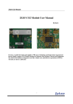
Spectrum (typical)
Fsample = 10MHz.
Fin = 1MHz sine.
Harmonics at 3 and 5MHz are due to signal generator.
SMT356356 User Manual