1
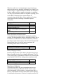
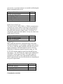
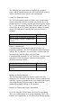
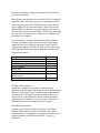
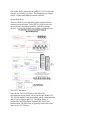
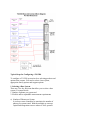
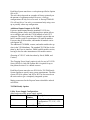
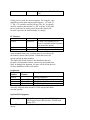
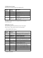
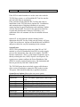
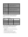
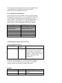
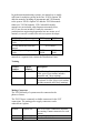
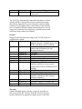
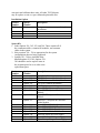
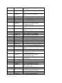
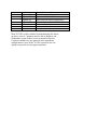
Configuration Guide
For the Agilent TS-5500 Family of
Cellular Phone Functional Testers
Table of Contents
Introduction
Planning
Test Plan
Customization
Maintenance, Installation, Support
Identify Requirements
Equipment
Installation, Training, Support, Maintenance
Configure the TS-5500
Complete TS-5500 Products and Options
Introduction
This document addresses configuring and ordering the TS5500. This includes selecting options to create a specific test
stand and the customization considerations necessary to
complete the tester. Other literature describes the features,
capabilities, and test software development environment for the
TS-5500 Family. This Configuration Guide considers the
complete system requirements to make a very good first pass
configuration of the TS-5500. Since configuring the TS-5500
requires detailed knowledge of both the test system and the
mobile phone, you must work closely with Agilent's system
engineers to develop a final configuration.
To configure the TS-5500 you should be planning at least these
items:
1. Test Planning
You need to plan and identify the tests that need to be
performed at the specific test stage and the requirements of the
system to make these tests
2. Customization Activities
Since you build a complete system from the TS-5500 platform,
customization planning becomes an important step in
configuration. For example, you need to consider interfacing to
fixtures and automation, completing the test plan, operator
interface and serial phone communication software before
selecting the appropriate options.
3. Line/System Installation and Support
Any system that is installed into the manufacturing line needs
planning for the installation and support. When you configure
the TS-5500, you need to consider supplying ac mains power,
system up-time support, application support and training.
1. Planning
Test
Planning
Customization
System
Installation
and
Maintenance
2. Identify
Requirements
DMM
Audio
Switching
RF Test Set
Power Supplies
RS-232
DIO
System Power
3. Configure
HP TS-5500
E8432A
Option 002
E2181A
Option 041
E8705A
E8710A
etc.
Fixtures
Installation Options
Support options
After planning the test requirements, customization, installation
and support, you should be able to list the requirements,
resources and equipment needed. The final step in this process
is to configure the TS-5500 using the Agilent models and
option numbers.
1. Planning
Test Planning
The first step in configuring the TS-5500 is to identify the tests
that are to be performed in the specific test stage. The TS-5500
includes or can be configured to handle the following general
areas of testing. Most mobile phones have these areas or
groups of tests performed at various manufacturing stages. This
discussion is intended to help you configure the necessary TS5500 options.
Turn-on Tests
When the mobile is in its loaded printed circuit board stage,
many turn-on tests are generally performed. For example, you
would configure a Digital Multimeter (DMM) and multiplexer
for basic probing of power supplies, test points, or continuity.
You may also download software to the phone requiring you to
use the RS-232 interface plus custom software for
communicating with the phone. More sophisticated testing
could require flexible switching of stimulus/response
instruments.
Equipment Needed
One DMM
One Multiplexer per phone
Additional Multiplexers
Flexible Low Frequency Switching per
phone
One RS-232 per Phone
Yes/No
Battery Emulation and Measurement
A very important test requirement is checking the mobile's
circuitry for the appropriate draw on the battery. Battery life on
the mobile is a critical end user feature and directly related to
the voltage/current characteristics. The 66312/32 Dynamic DC
Measurement Source is used for battery emulation and
measuring current draw at various levels.
Equipment Needed
Agilent Dynamic DC Power Supply
Yes/No
Battery Charging Circuitry
Besides testing the draw on the battery, the phone may have a
battery charging circuitry for re-charging the battery. The TS5550 system offers a combination of the 6612 for powering the
circuit and 66312/66322 for sinking and measuring currents.
Equipment Needed
Dynamic DC Power Supply
6612 Power Supply
Yes/No
Phone Power Calibration
All mobiles must have the power transmitter and receiver
adjusted and frequency calibrated. The RF Test Set is the
critical instrument for this testing. A communication link, i.e.
RS-232, to the internal circuitry of the phone is also required
for making the adjustments. Sometimes a signal generator, RF
power meter, or spectrum analyzer are needed in calibrating the
phone's transmitter and receiver.
Equipment Needed
One RF Test Set per phone
One RS-232 per Phone
Special RF Signal Generator
Special Power Meter
Special Spectrum Analyzer
Yes/No
Radio Tests or Final Tests
The classic tests for GSM, CDMA, or TDMA communication
verification are always made at some stage in the production
line. Sometimes these tests are made with communication to
the mobile and sometimes testing is done "over-the-air" or
using the RF connection on the phone. In any case, these tests
require the RF Test Sets.
Equipment Needed
One RF Test Set per phone
One RS-232 per Phone
Yes/No
Audio Tests
Many production lines have automated testing of the audio
circuitry in the phone, e.g. microphone, speakers, and circuitry.
You can use either the audio capability in the RF Test Set or a
higher performance VXI DSP module in the TS-5550. For
single tone or multi-tone stimulus/response testing, use VXI
E1432 DSP with the supplied connections through the mass
interconnect. The TS-5550 has the Audio Source Multiplexed
to the BNC's on the ExpressConnect. The audio inputs are
multiplexed to the DSP via the eight channel breakout box.
Phone communication may be needed in this test, depending on
the specific requirements.
Equipment Needed
Audio in RF Test Set
One Audio VXI DSP Module
One RS-232 per Phone
Customization Activities
Yes/No
The following are typical tasks to complete the cell phone
tester. Adding customization to the TS-5500 Platform creates a
custom system that meets specific test requirements.
Create Test Plans and Actions
The TS-5500 includes generic test plans, tests, measurements,
actions, and utilities to build a custom test plan for any of the
testing required. To create test plans and custom actions written
in C++, you will need the Developer Software and License. To
run the tests on an TS-5500 the appropriate software is loaded
on the VXI Embedded Controller and a run-time license is
included.
Hardware/Software Needed
One PC for up to four sets of equipment
One Developer Software, Manuals and
License
Developer Training
Yes/No
Phone Communication
Communicating with the phone's internal circuitry is a
proprietary technique. The TS-5500 supplies general hardware
with the RS-232 interface. You can create a custom action for
communicating with the phone using the Phone
Communications Assistant. Or, you can create a custom action
using the TS-5500 Developer's software which includes
Microsoft Developer Studio.
Hardware/Software Needed
One RS-232 per phone
One Developer Software, Manuals and
License
Yes/No
Interface to Factory Database
The TS-5500 stores parametric data for each test on each
mobile in a file. Transfer of this data to a factory computer that
runs SQC reports or supports factory-wide information requires
some programming. Post processing of this test data in
standard spreadsheet software is also possible.
Interface to Fixture and Factory Automation
If you are using the TS-50 Fixtures for Final Test and Board
Test, your customization job is greatly simplified. The TS-50
Fixtures are complete kits, so you only need to add the custom
interface to the phone. Design and cabling to the TS-5500 is
provided as an option.
Many factory automation devices use an RS-232 or Centronics
Parallel interface. These devices can be controlled by the TS5500 using the System RS-232/Parallel Ports. Many fixtures
require digital I/O for sense and control. Other fixtures may
require an RS-232 interface. A general purpose relay may be
used to switch a device on/off. Fixtures and factory automation
may use power from the system. This power is supplied with
the utility power supplies.
For each system, a custom cable/interface from the Express
Connect to the phone/fixture must be created. The mating
connector parts are available to create this cable. Since RF
cabling is not supplied with the TS-5500, the RF connections
and cabling from the instruments to the phone should also be
designed and created.
Equipment Needed
RS-232/Parallel control for each fixture
Low power sense/control
General Purpose Switching
Barcode Reader
Strip Printer
Utility Power
Express Connect Mating Connectors to
cable to fixture
Fixture Kit(s)
Yes/No
RF Path Characterization
Agilent has created specific software routines to help
characterize the RF path in the system and store the appropriate
offsets in a table that is used to automatically compensate the
measurements. The Signal Generator and Power Meter are
used to create a semi-automatic characterization procedure.
Agilent provides examples so you can create a test plan for
characterization and use an operator interface panel.
Other RF Measurements
Testing a specific phone design may require out-of-band
spurious measurements or low level measurements with a
spectrum analyzer. In addition, an antenna test would require a
spectrum analyzer, either built into the RF Test Set or
standalone.
Hardware/Software Needed
TS-5500 Developer Software
TS-5500 RF ExpressConnect Hardware
Custom RF Path Hardware
Power Meter
Signal Generator
Spectrum Analyzer
Yes/No
Operator Interface
Agilent supplies a sample operator interface that manages a
four-up system, including operator log-ins, starting test plans
and fixtures. A custom operator interface should be developed
using the Visual Basic software provided in the TS-5500
Developer Software package. The TS-5500 system does not
include display, mouse or keyboard, so an appropriate SVGA
display, PC mouse and local language keyboard must be
ordered separately. Special Touch screen displays or large
displays may be needed.
Hardware/Software Needed
TS-5500 Developer Software
Local Language Keyboard
PC Mouse
SVGA Display
Visual Basic Training
Special PC Monitor
Yes/No
Database Interface
The TS-5500 logs all parametric and pass/fail information
stamped with date, time and serial number to a file. Factory
databases or SQC software will need to access this data.
Typically a custom program is created to upload the data to a
central computer from each test system. While the test data is
in standard formats, many times it is formatted to fit with the
factory computer systems.
System Maintenance and Installation Considerations
Installation
The TS-5500 System must be connected to a dedicated circuit
in the factory. This main factory circuit is connected to the
Power Distribution Unit (PDU). The PDU can be configured
for numerous power situations. Typically, this work is done by
an electrician. Other installation considerations include
physical layout of the equipment rack and connecting to the
fixtures and assembly line or automated equipment. Refer to
the manual Chapter 2 System Installation for more details on
site preparation and system power.
Support Planning
Since most factories want maximum uptime for these systems,
a cooperative support plan should be developed. The
manufacturing site should have people trained to verify and
diagnose system failures using the TS-5500 verification fixture
and test plan. The manufacturing site should have a spare parts
inventory. Agilent will provide back-up support with phone
assistance and next day on-site support.
Support Needed
System Installation
Verification Fixture, Verification Test
Plan and Diagnostics
Spare Parts Kit
Maintenance Training
Yes/No
2. Identify Requirements
At this point in the configuration process, a list of the
requirements and resources needed to configure the system has
been developed. Here is an example list of potential resources
needed:
q
q
q
q
q
q
q
q
q
q
q
q
q
q
q
q
q
q
q
q
q
q
q
q
q
q
q
q
q
q
q
q
DMM
Multiplexer
RS-232 per phone
Battery Emulation power
Battery Charger Power
RF Test Set per phone
Audio
Developer Software and License
Manuals
DIO for fixture control
RS-232 for fixture control
Utility power for fixtures
General purpose switching
Utility power for GP switching
Matrix switching
Mating connectors for mass interconnect
RF connections
Other RF instruments for path characterization
Operator Interface panel/software
Custom software routine
Bar Code reader via RS-232
Strip Printer via RS-232
PC Monitor, Keyboard, Mouse
Test Developer Training
Site Preparation
System Installation
Power to system
Spare parts
Diagnostic/Verification Tools
Maintenance Training
Technical Support
3. Configure TS-5500
TS-5500 System Design Overview
It is important to have an understanding of the system design to
make the proper choices for configuration. The TS-5500
Product Notes cover the features of each of the hardware and
software pieces in the system. This configuration discussion
builds on that knowledge and introduces more internal design
concepts, including types of resources and interconnection
diagrams.
TS-5500 Family of Systems
There are two members of the TS-5500 family: TS-5530 and
TS-5550. The following table offers a quick comparison of
features and capabilities:
You should select one of the systems as the basis of your
configuration. The following table is a comparison based on
application requirements:
DIO
RS-232
Number of Phones
Charging Circuitry
DMM
Other VXI
Instruments
Audio Tests
TS-5530
96 channels max
Two per phone;
four system RS232
One or two per
system
No
No
No
Use RF Test Set
TS-5550
Only limited by
VXI modules
Only limited by
VXI modules
Two to four per
system
Yes
Yes
Yes
VXI DSP Option
For comparison purposes the following items are identical for
each of the two family members:
Test Executive Software
Software Test Plans, Actions, Measurements and Utilities
Rack sizes, power distribution
Integration and Cabling
PC, Mouse, Keyboard and Monitor
RF Test Sets (GSM,CDMA, TDMA, PCS)
Manual Fixture Solution
TS-5500 Resources
The TS-5500 has "shared", "system", and "per UUT" resources
that must be understood to configure a system.
Shared Resources
One Audio DSP is shared for the multiple UUT's because the
test time is generally very short. The charging power supply
(6612), Counter and DMM are shared resources.
System Resources
There are RS-232 ports and utility power supplies that are
common for each system. These RS-232 ports are used for
driving factory automation, handlers, and other operator
devices, e.g. barcode readers, strip printers, or button boxes.
"Per UUT" Resources
Since the RF Test Set (892x) does the bulk of the
measurements on the phone, one is required per phone/UUT.
The VXI M-modules used in switching, phone communication
and I/O are configured per UUT. The phone battery is
emulated by the 66300 Series Dynamic DC Source and
Measurement. The DIO lines are typically used to drive and
sense in each UUT fixture.
Typical Steps for Configuring a TS-5500
To configure a TS-5500 system involves selecting products and
options from a menu. You need to select a base system,
appropriate family options and support options.
1. Selecting a Base System
There are a few key decisions that allow you to select a base
system. You must decide:
1. Number of phones per system and
2. Flexible and/or expandable measurement requirements
a) Number of Phones per System
It is always most economical to maximize the number of
phones per system tested. With the multiple-up concept,
capital and integration costs are reduced. Also, operator
interfaces are minimized, e.g. strip printers, monitor,
barcode readers.
Some of the considerations in maximizing the number of
phones tested per system relate to the philosophy of testing,
optimizing test times, and integration into the
manufacturing floor.
Testing using a multiple-up philosophy is a relatively new
concept and may be perceived as risky. For example, if the
test system fails, multiple stations will be down. Since the
highest failure rate items in a test system are the "per UUT"
resources, such as the RF Test Set, there is an insignificant
failure rate difference between the multiple-up strategy and
a one-up philosophy. The multiple-up TS-5500 will simply
run only test plans for the working RF Test Sets.
With the shared resource concept in the TS-5500,
sometimes the system computer will need to arbitrate the
usage of the shared resources, e.g. audio test module or
DMM. Also with a four-up system, the overhead on the
system computer running four concurrent sets of equipment
may be a 5 to 7% burden. So, if maximizing test time is the
over-riding factor above the savings on integration and
capital costs, then reduce the number of UUT's tested per
system.
When integrating the TS-5500 into the manufacturing line,
consider physical layouts, regulatory requirements, and
fixturing issues. For example, in some factories 2m height
racks may not be allowed. Sometimes, operators must
move a significant distance between fixtures, so a common
monitor, barcode reader, and printer becomes less effective.
If the fixtures are large and spaced apart, the test operator
may need to move large distances between
loading/unloading four fixtures and handling the shared
barcode reader.
Number of Phones
Tested Per System
One
Two
Three
Four
TS-5500 Base Model
Number
E8431A
E8432A or E8452A
E8453A
E8454A
2. Flexible and/or Expandable Measurement Requirements
If you want a two-up system, then you must decide between the
TS-5530 and TS-5550 configurations. The TS-5550 is the most
flexible and expandable. The TS-5530 provides just enough
test capability for a lower cost.
Examples of flexibility included in the TS-5550 are
a. DMM and/or Switching
One DMM is included in the base TS-5550 systems for
shared measurements. A multiplexer is connected to the
DMM for each UUT. The DMM is also required for using
the system verification and diagnostics fixture. If the test
plan requires a significant amount of DMM probing,
consider an additional DMM per UUT to decrease test
time. By adding a DMM per UUT, it will no longer be a
shared resource.
b. Audio Test Module
Both family members can use the RF test set capability to
verify audio with a single tone source and measurement.
The TS-5550 has an Audio Test Module based on the VXI
DSP card. It is a shared resource for all UUT's in the test
system. Each option provides for multiple inputs and
outputs for each phone tested per system. A single audio
source is switched to the different UUT points using a
built-in mux. Audio measurements are also multiplexed via
special signal conditioning to the VXI DSP card.
c. Optional M-modules per phone
More M-modules for switching, sensing or controlling can
be added to the system. For example, driving an automated
fixture will require more than the standard number of DIO
lines. Each UUT should have the same additional Mmodules.
d. Checking Battery Charging Circuitry
If you are testing the phone's battery charging circuitry, the
6612 can be added in the TS-5550 systems.
2. Select Common TS-5500 Family Configurations
a. RF Test Sets and RF path
One RF test set is required for each phone tested in the system.
An RF path is available from Agilent as an option or as custom
work. The RF path characterization software is provided with
the TS-5500.
b. Rack Size
The TS-5500 offers racks in two heights: 1.6m and 2.0m. You
should add up the total amount of rack space needed for the
spacific configuration before choosing a rack size. Any four-up
system requires the 2.0m rack. PCS or GSM-dual-band the RF
Test Sets require more rack space, so you will need to trade off
the number of phones tested per system versus rack height. For
example, with PCS or GSM-dual-band RF test sets, a 1.6m
rack is limited to a 2-up configuration.
c. PDU Power (200-400V)
The TS-5500 requries a dedicated ac mains power circuit. This
power circuit should be installed by a certified electrician.
The options and configuration matrix from the manual
Cabling done by electrician.
d. Utility Power Configuration
Also, you need to configure the utility power supply for
connecting to fixture, automation equipment or other circuitry.
e. Operator Options
A 17 inch monitor should be chosen via option. Touch screens
can be added as a special option.
The Keyboard, mouse and Monitor connections to the TS-5500
are via the ExpressConnect. Depending on the position of the
keyboard, mouse and monitor, extension cables may be
needed.
The four RS-232 ports on the TS-5500 ExpressConnect have 9
pin connectors typical to those on a PC. These 9 pin connectors
are connected to the system printer using typical 9 pin to 25 pin
printer cables.
Be sure to consider the space the keyboard, mouse, monitor,
and/or printer will take. A small work surface may be added
into the rack as an option. Preferably, most manufacturing
environments have specific requirements and desires for the
operator's working area.
3. Select TS-5500 Support Configurations
Support options, training, developer license
Developer License E2174A
Included in the base system is license to runs software.
Included in Developer License is VB, C++, to develop custom
actions and operator/user interface.
The Developer License E2174A includes manuals?
Standard Configurations; Rack drawings
4. Complete TS-5500 Products and Options
To completely configure a TS-5500 system, you need to select:
• Base System
• Family System Options
• System Support Options and Accessories
TS-5500 Base Systems
One-up TS-5530 Base System
Product Number
E8431A
Description
TS-5531 Base System tests one mobile phone and
includes:
Vectra with hard disk, CD-ROM, 3 1/2 floppy, LAN
Card, and Windows NT 4.0; HP-IB interface
Built-in RS-232 channels: 2 for phone
communications and 4 for system I/O (such as bar
code readers)
28 TTL DIO channels and 4 open-collector DIO
channels
One Phone power supply (66311B)
Utility Power Supplies (configured with E2181A)
TS-5530 Series ExpressConnect
Test executive and instrument drivers software
Systems Integration of all options and standard
instruments, including choice of rack and all racking
hardware
Power Distribution Unit to power instruments and
fans (power cord and connector to ac mains not
included)
E8431A Option 030 1.6 meter rack
E8431A Option 031 2.0 meter rack
E8431A Option 250 ExpressConnect RF Interface for Signal Generator
Two-up TS-5530 Base System
Product Number
E8432A
Description
TS-5532 Base System tests two mobile phones and
includes:
Vectra with hard disk, CD-ROM, 3 1/2 floppy, LAN
Card, and Windows NT 4.0; HP-IB interface
Built-in RS-232 channels: 4 for phone
communications (2 per phone) and 4 for system I/O
(such as bar code readers)
28 TTL DIO channels and 4 open-collector DIO
channels per phone
Two Phone power supply (66311B)
Utility Power Supplies (configured with E2181A)
TS-5530 Series ExpressConnect
Test executive and instrument drivers software
Systems Integration of all options and standard
instruments, including choice of rack and all racking
hardware
Power Distribution Unit to power instruments and
fans (power cord and connector to ac mains not
included)
E8432A Option 030 1.6 meter rack
E8432A Option 031 2.0 meter rack
E8432A Option 250 ExpressConnect RF Interface for Signal Generator
Two-up TS-5550 Base System
Product Number
E8452A
Description
TS-5552 Base System tests two mobile phones and
includes:
Vectra with hard disk, CD-ROM, 3 1/2 floppy, LAN
Card, and Windows NT 4.0; HP-IB and P1394
(Firewire) interfaces
C-size VXI Cardcage
System Resources:
Two RS-232Centronics and two 16 Channel DIO
One shared DMM with Multiplexer per phone
Quad RS-232 M-module per phone
Two Phone power supply (66311B)
Utility Power Supplies (configured with E2181A)
TS-5550 Series ExpressConnect for two UUT's
Test executive and instrument drivers software
Systems Integration of all options and standard
instruments, including choice of rack and all racking
hardware
Power Distribution Unit to power instruments and
fans (power cord and connector to ac mains not
included)
E8452A Option 030 1.6 meter rack
E8452A Option 031 2.0 meter rack
E8452A Option 210 RS-232/Centronics M-module (Includes one RS232/Centronics M-module and ExpressConnect
Cable)
E8452A Option 211 Quad RS-232 M-module (Includes one quad RS-232
M-module and ExpressConnect Cable)
E8452A Option 215 16 Channel GP Relay M-module (Includes one 16
Channel GP Relay M-module and ExpressConnect
Cable)
E8452A Option 216 4 x 4 Matrix M-module (Includes one Matrix Mmodule and ExpressConnect Cable)
E8452A Option 217 Dual 8-to-1 Mux M-module (Includes one
Multiplexer M-module and ExpressConnect Cable)
E8452A Option 218 16 Bit I/O M-module (Includes one 16 Bit Digital
I/O M-module and ExpressConnect Cable)
E8452A Option 250 ExpressConnect RF Interface for Signal Generator
E8452A Option 410
E8452A Option 415
E8452A Option 416
E8452A Option 420
E8452A Option 480
DSP Audio Test Module
Additional DMM per phone
Add 16 DMM Input Channels per phone
Two channel Frequency Counter (shared resource)
0 - 20 V DC Charging Supply (Includes one 6612
Power Supply, cabling and integration)
E8452A Option 760 TS-5550 Verification Fixture
Three-up TS-5550 Base System
Product Number
E8453A
Description
TS-5553 Base System tests three mobile phones and
includes:
Vectra with hard disk, CD-ROM, 3 1/2 floppy, LAN
Card, and Windows NT 4.0; HP-IB and P1394
(Firewire) interfaces
C-size VXI Cardcage
System Resources:
Three RS-232Centronics and three 16 Channel DIO
One shared DMM with Multiplexer per phone
Quad RS-232 M-module per phone
Three Phone power supply (66311B)
Utility Power Supplies (configured with E2181A)
TS-5550 Series ExpressConnect for three UUT's
Test executive and instrument drivers software
Systems Integration of all options and standard
instruments, including choice of rack and all racking
hardware
Power Distribution Unit to power instruments and
fans (power cord and connector to ac mains not
included)
E8453A Option 030 1.6 meter rack
E8453A Option 031 2.0 meter rack
E8453A Option 210 RS-232/Centronics M-module (Includes one RS232/Centronics M-module and ExpressConnect
Cable)
E8453A Option 211 Quad RS-232 M-module (Includes one quad RS-232
M-module and ExpressConnect Cable)
E8453A Option 215 16 Channel GP Relay M-module (Includes one 16
Channel GP Relay M-module and ExpressConnect
Cable)
E8453A Option 216 4 x 4 Matrix M-module (Includes one Matrix Mmodule and ExpressConnect Cable)
E8453A Option 217 Dual 8-to-1 Mux M-module (Includes one
Multiplexer M-module and ExpressConnect Cable)
E8453A Option 218 16 Bit I/O M-module (Includes one 16 Bit Digital
I/O M-module and ExpressConnect Cable)
E8453A Option 250 ExpressConnect RF Interface for Signal Generator
E8453A Option 410
E8453A Option 415
E8453A Option 416
E8453A Option 420
E8453A Option 480
DSP Audio Test Module
Additional DMM per phone
Add 16 DMM Input Channels per phone
Two channel Frequency Counter (shared resource)
0 - 20 V DC Charging Supply (Includes one 6612
Power Supply, cabling and integration)
E8453A Option 760 TS-5550 Verification Fixture
Four-up TS-5550 Base System
Product Number
E8454A
Description
TS-5554 Base System tests four mobile phones and
includes:
Vectra with hard disk, CD-ROM, 3 1/2 floppy, LAN
Card, and Windows NT 4.0; HP-IB and P1394
(Firewire) interfaces
C-size VXI Cardcage
System Resources:
Four RS-232Centronics and four 16 Channel DIO
One shared DMM with Multiplexer per phone
Quad RS-232 M-module per phone
Four Phone power supply (66311B)
Utility Power Supplies (configured with E2181A)
TS-5550 Series ExpressConnect for four UUT's
Test executive and instrument drivers software
Systems Integration of all options and standard
instruments, including choice of rack and all racking
hardware
Power Distribution Unit to power instruments and
fans (power cord and connector to ac mains not
included)
E8454A Option 030 1.6 meter rack
E8454A Option 031 2.0 meter rack
E8454A Option 210 RS-232/Centronics M-module (Includes one RS232/Centronics M-module and ExpressConnect
Cable)
E8454A Option 211 Quad RS-232 M-module (Includes one quad RS-232
M-module and ExpressConnect Cable)
E8454A Option 215 16 Channel GP Relay M-module (Includes one 16
Channel GP Relay M-module and ExpressConnect
Cable)
E8454A Option 216 4 x 4 Matrix M-module (Includes one Matrix Mmodule and ExpressConnect Cable)
E8454A Option 217 Dual 8-to-1 Mux M-module (Includes one
Multiplexer M-module and ExpressConnect Cable)
E8454A Option 218 16 Bit I/O M-module (Includes one 16 Bit Digital
I/O M-module and ExpressConnect Cable)
E8454A Option 250 ExpressConnect RF Interface for Signal Generator
E8454A Option 410
E8454A Option 415
E8454A Option 416
E8454A Option 420
E8454A Option 480
DSP Audio Test Module
Additional DMM per phone
Add 16 DMM Input Channels per phone
Two channel Frequency Counter (shared resource)
0 - 20 V DC Charging Supply (Includes one 6612
Power Supply, cabling and integration)
E8454A Option 760 TS-5550 Verification Fixture
The base systems are a core set of equipment for testing one to
four phones.
They include the serial interfaces, digital I/O, phone and utility
power, power distribution, racking, cabling, and PC.
The TS-5550 Base Systems includes the fundamental VXI
modules for serial interface with two phones and a modest
amount of sensing and control. The Dual RS-232/Centronics
module and 16 bit Digital I/O are intended to control each
fixture and phone. One Quad RS-232 is also included for
control of barcode readers and other system peripheral devices.
Considering the potential need for additional I/O for each
phone or fixture control, extra VXI M-module carriers are
included in the base system. A utility power supply is included,
but it must be configured with a "no charge" Family Option.
The system power must be configured with the Family Options
05A - 0EJ.
Each of the base systems has one phone power supply and two
RS-232's per phone tested. One Phone Power Supply is
required for each phone tested in the system, so it is included in
the base system. In a multiple-up system, we rack mount two
66311B's beside each other to save rack space.
The software in the base system is a run-time version of the
TS-5500, so it executes from the operator interface, but you
can not develop test plans or actions. Order the E2174B to get
test development software.
You must have one development License per engineer. See
E2181A opt. 370.
Because the TS-5500 is intended for use in manufacturing,
manuals are not included with the base system.
Rack Choices
Each Base System must have a rack option specified as Option
030 or 031.
The rack choice depends on a number of factors, primarily on
the amount of equipment needed. However, a four-up
configuration will only fit in a 2m rack. A four-up TDMA/IS136 will not fit in a 2 m rack; we recommend only using a twoup or possibly a three-up configuration.
Additional Inputs/Outputs in TS-5550
For more inputs/outputs than the standard TS-5550, the
following options can be used. Ordering these options allows
us to configure and cable the VXI M-module to each UUT
connector. The Base system has 4 M-module carriers that can
hold 5 modules each for a maximum of 20 total M-modules.
For more than 20 M-modules, add another M-module carrier
with Option 205.
The additional VXI DMM, counter, and audio module take up
slots in the VXI Mainframe. The standard TS-5500 has 6 slots
taken by the Firewire interface, DMM, and M-module carriers,
leaving 6 slots for other instruments or M-module carriers.
(Drawing of VXI CC with slots taken by Slot 0, DMM, and
Carriers)
The Charging Power Supply option is only for use in TS-5550
Series (E845xA). Only one Option 480 is required for up to
four phones because it is a shared resource.
Each Base System must also use E2181A for TS-5500 Family
System Options to specify more system requirements. The base
system, E2181A options, and E87xx RF Test Sets must be on
the same order to get a completely integrated system.
Mating connectors for the ExpressConnect should be ordered
as E6244A.
TS-5500 Family Options
Utility Power Supply Configurations
(Must order one utility power supply option)
Product Number
Option
Description
Number
E2181A
Option 041
Utility Power Supply
Configuration: 5V, +12V, -12V,
24V
E2181A
Option 042
Utility Power Supply
Configuration: 3.3V, 5V, 12V,
24V
Utility power is used for various purposes. For example, a preamplifier used for audio testing would require + 12V and -12
V. The +5V would be used for pull-ups. The 24V is typically
used for actuators and switches, e.g. RF switches. If you don't
have a preference for utility power, then order Option 041,
because it provides the best flexibility of voltages.
PC Monitors
E2181A
Option 051
17 Inch Color Monitor for PC
(Price is included in Base Systems,
but must order option)
E2181A
Option 050
Work Surface (not installed)
A 17 inch monitor is included in the base system. The monitor
is not mounted in the rack, so plan a space on a work area for
the monitor, mouse and keyboard. Consult the factory for
special options on other monitors.
The Option 050 Work Surface is not installed in the rack
because it will protrude from the system rack and would most
likely be damaged in shipment. As space will be left in the rack
for easy installation of the work surface.
Peripherals
Product
Number
E2181A
Option
Number
Description
Factory peripherals
Option 070
Fixed Position Barcode Scanner Kit
Option 071
RS-232 Handheld Barcode Scanner Kit
Option 080
RS-232 Strip Printer
These factory peripherals are not installed in the rack, so you
can easily integrate them into the TS-5500 and position them
near the operator.
Optional RF Equipment
E2181A Option 450 Signal Generator integrated into TS-5500 (For use
with ExpressConnect RF Interface; E4420B with
Option 1E5)
Other RF equipment is supplied as a special option; consult the
factory.
TS-5500 Software Formats
Must choose one software format to be installed on PC.
Product
Number
E2181A
Option
Number
Option 305
Option 310
Option 311
Option 315
Option 320
Description
Analog Support
GSM/8922 Radio Format
GSM/8960 Radio Format
TDMA Radio Format
CDMA Radio Format (For either 8924C
or E8285A)
Option 370
TS-5500 Test Development Software
Installed on PC
These options allow for a run time license on the test systems.
The Option 370 allows the test development and test execution
on the same system.
Mobile Phone Test Sets
The TS-5500 system must include RF Test Sets or the options
050/051 below. There must be one RF Test Set per phone.
1. GSM, GSM/DCS/PCS Choices
Product
Number
E8709A
Option
Number
Option 050
Option 051
E8710A
Option 001
Option 050
Option 051
E8711A
Option 001
Option 050
Option 051
2. CDMA, CDMA/PCS
Description
Integrates 8960 GSM Test Set into TS5500 (Includes E5515A and E1960A)
Customer-supplied 8960
Customer-installed 8960
Integrates 8922M GSM Test Set into TS5500 (Includes 8922M and Option 006)
High Stability Timebase for 8922M
Customer-supplied 8922M
Customer-installed 8922M
8922P GSM/PCS Multi-band Test Set
(Includes 8922P and Option 006)
High Stability Timebase for 8922P
Customer-supplied 8922P with PCS
Customer-installed 8922P with PCS
Product
Number
E8712A
Option
Number
Option 050
Option 051
E8713A
Option 050
Option 051
E8713B
Option 050
Option 051
Description
Integrates 8924C CDMA Test Set into
TS-5500
Customer-supplied 8924C
Customer-installed 8924C with PCS
Integrates 8924C CDMA Test Set with
PCS into TS-5500
Customer Supplied 8924C with PCS
Customer-installed 8924C with PCS
Integrates E8285A CDMA/PCS Test Set
into TS-5500
Customer Supplied E8285A
Customer-installed E8285A
3. TDMA, IS-136, Analog
Product
Number
E8714A
Option
Number
Option 001
Option 050
Option 051
E8715A
Option 001
Option 050
Option 051
E8716A
Option 001
Option 050
Option 051
Description
Integrates 8920B TDMA Test Set into
TS-5500 (Includes 8920B with Options
800,
0B0, 004, 006, 013, 014, 031, 051, 102,
and appropriate rack mounting )
High Stability Timebase
Customer-supplied 8920B/800
Customer-installed 8920B/800
Integrates 8920B TDMA/PCS Test Set
into TS-5500 (Includes 8920B with
Options 801, 0B0, 004, 006, 013, 014,
031, 051, 102, and appropriate rack
mounting )
High Stability Timebase
Customer Supplied 8920B/801
Customer-installed 8920B/801
Integrates 8920B (Analog only) into TS5500
(Includes 8920B with Options 0B0, 004,
006, 013, 014, 031, 102, and appropriate
rack mounting )
High Stability Timebase
Customer Supplied 8920B
Customer-installed 8920B
If the E87xxA model numbers are on the same order with the
TS-5500 base system, we will install the RF Test Sets into the
rack and cable them as appropriate.
If the customer already owns the RF Test Sets and wants to
install them in the TS-5500, the use Option 050. Coordination
and communication of shipping information is necessary;
contact Agilent for special instructions and conditions. Agilent
will also check the RF Test Sets for the appropriate firmware
revision and download new firmware if necessary. A recalibration of the cal constants will also be included with new
firmware.
Option 051 is used when the customer already has the
appropriate 89xx RF Test Set. In this case the factory will leave
a space for each test set. Agilent will install the rails and HP-IB
and power cables for easy rack mounting by the customer.
System Power
All TS-5500 configurations require more than 20A at 120V
nominal, so a Power Distribution Unit (PDU) is used to supply
power to the instruments, fans, and power supplies. The PDU
must be connected to >200 V, so the amperes required is lower,
thereby reducing the size (AWG) of power cord required. The
system power options configure the Power Distribution Unit
(PDU) to accept a certain ac mains power. The instruments and
fans are powered by 200-240V from the PDU.
The TS-5500 System does not include a power cable because
of the variety of methods to connect the PDU to the ac mains.
This power cable should be added by a qualified electrician.
System Power Options (Must order one power option)
Option Number
Description
Option 05B
220V Two Phase, Open Delta; P Junc Earth; 3wire
Option 05C
220V Three Phase or Wye; 3-wire
Option 05E
220V Three Phase Wye with Neutral; 4-wire
Option 05F
230V Single-Phase Earthed; 2-wire
Option 05G
230V Two Phase, Open Delta; P Junc Earth; 3 wire
Option 05H
230V Three Phase Delta or Wye; 3-wire
Option 05J
240V Single-Phase Earthed; 2-wire
Option 05K
240V Two Phase Open Delta; P Junc Earth; 3-
Option 05L
Option 05M
Option 05V
Option 0E3
Option 0E5
Option 0E6
Option 0E7
Option 0EB
Option 0EC
Option 0EF
Option 0EG
Option 0EH
Option 0EJ
wire
400V Three Phase Wye with Neutral; 4-wire
220V Single-Phase Earthed; 2-wire
200V Single-Phase Earthed; 2-wire
200V (200V to 240V) Power
380V Three Phase Power
240V Three Phase Delta or Wye; 3-wire
415V Three Phase Wye with Neutral; 4-wire
220V Single-Phase Non-Earthed; 2-wire
240V Single-Phase Non-Earthed; 2-wire
208V Three Phase Wye with Neutral; 4-wire
220V Single Phase CT; 3-wire
240V Single Phase CT; 3-wire
230V Single Phase Non-Earthed; 2-wire
These power options apply to all base system models: E8431A,
E8432A, E8452A, E8453A, and E8454A. This PDU and its
configuration are the same as the 3070 Board Test System
PDU.
System Current Requirements
System
Current Required
Configuration
at 220V Nominal
E8452A (2-up)
21A
E8453A (3-up)
E8454A (4-up)
E8431A(1-up)
E8432A (2-up)
Each TS-5500 system must have power provided to the PDU
from the ac mains at the installation site. The TS-5500 requires
a dedicated circuit to be installed by a certified electrician.
Option W41 provides assistance in installing the system.
Option W41 includes:
• System unpacking and removal of packing material from
customer site
• Attachment of monitor, keyboard, mouse and LAN cable to
embedded PC
• Power cord connection to system's PDU
• Work surface installation (if Option 050 is ordered)
• Confirmation of hardware and software installation
• System verification using the TS-5500 Diagnostic fixture
The RF path characterization to the phone is not included with
system installation. RF path characterization should be
included with test development activities.
Power Option Recommendations
An electrician may not be available to advise you in selecting
the appropriate power option, so we recommend the following
TS-5500 power options based on our knowledge of local ac
mains available. To change the power option/configuration for
connecting to ac mains involves re-wiring the PDU locally.
Refer to the 1135 Power Distribution Unit User's Manual.
Country/Region
USA,Canada
Europe/Australia
PRC
Japan
Korea
Taiwan
Hong Kong
TS-5500 Option
Option 0EF
Options 05M, 05F, 05J
Option
Option 05V
TS-5500 Support Options and Accessories
Test Development Software
Product Number
Option
Number
E2174B
Description
TS-5500 Action Development
Software and License (includes
license, software, Visual basic, and
Visual C++. Required for custom
action or operator interface
development)
Each test developer must purchase this software and license. A
site license is not available. The TS-5500 software is shipped
on CD. So, the E2174B allows test developers to install this
software on their development computer and system.
Manuals
E2182A
Option 700
Option 705
Adds VXI and instrument manuals
Adds TS-5500 Programming
Manuals
In production/manufacturing systems, one manual set is usually
sufficient for multiple systems on the line. E2182A Option 700
adds the manuals, including all instruments and VXI manuals
to the system. E2182A Option 705 adds the TS-5500 manuals.
Otherwise, TS-5500 manuals, VXI Card and M-module
manuals are not included; other Instrument manuals (89xx,
66312) are also not included. Usually the customer's
production/test engineering department has one master set of
manuals, or one set is ordered for each test system developer.
TS-5500 Manuals
GSM
CDMA
TS-5500 ExpressConnect Wiring
E2170-90006
Guide
TS-5500 Hardware Reference
E2170-90007
Manual
TS-5500 System Programming
E2170E2189Guide
90000
90000
To obtain these manuals, VXI manuals, or other instrument
manuals as a separate item, contact the Distribution Center.
Training
Product
Number
E2182A
Option
Number
Option 710
E2182A
Option 720
Description
User Training Course (in Loveland CO
USA, price is per student, includes
materials and 3 days training)
Maintenance Training Course (in
Loveland CO USA, price is per student,
includes materials and 5 days training)
Mating Connectors
The TS-5500 family of systems must be connected to the
phone or fixture.
The TS-5530 uses commonly available connectors for the UUT
connections. The mating power supply connectors can be
ordered from Agilent.
E6244A
Option 005
Option 013
Option 014
TS-5550 Fixture Connectors (Includes
two mating Cannon connectors for each
phone.)
Crimp Tool for Canon connector contacts
Extractor Tool for Canon connector
Option 015
Option 016
Crimp Tool for AMP Power Connectors
Extractor Tool for AMP Power
Connectors
The TS-5550 is mechanically connected to the phone or fixture
with the E6244A. One E6244A must be ordered at no charge,
then add one Option 005 to receive the parts to build a mating
connector for each phone/fixture. One crimp tool and extractor
tool is required to build the mating Cannon connectors. For the
Amp power connectors the crimp tool is optional because both
solder and crimp contacts are included.
Fixtures
Manual Fixture Kits that easily adapt to the TS-5500 family are
available from Agilent.
E8705A
TS-50 RF Final Fixture Kit (Includes
shielded enclosure, adaptable phone nest,
PCB for shielding and level shifting)
Option 101
Audio Test Adapter Kit (Includes
speaker and microphone pick-ups,
mounting hardware)
Option 005
Five Pack
Option 010
Ten Pack
Option 105
Five Pack of Audio Kits
Option 110
Ten Pack of Audio Kits
Option 700
TS-50 Assembly Manual
E8706A
TS-50 RF Board Test Fixture Kits
(Includes shielded enclosure, board
compression, PCB for shielding and level
shifting)
Option 005
Five Pack
Option 010
Ten Pack
Option 201
Standard Board Test Adapter Kit
(Includes 3 boards for pins, compress
boards, pin shields)
Option 205
Five Pack of Board Test Adapter Kit
Option 210
Ten Pack of Board Test Adapter Kit
Option 700
TS-50 Assembly Manual
Warranty
Agilent's standard system warranty is one year, next-day onsite, except for the RF Test Sets. If the RF Test Sets fail, they
must be returned to an appropriate Agilent service center that
can repair and calibrate these units. All other TS-5500 parts
may be replace on-site as a pre-calibrated replaceable unit.
Installation Option
Product
Option
Number
Number
E2182A
W41
Description
One year on-site warranty with Agilent
Installation
Spares Kit
1. Order Options 301, 302, 303, and 304. These contain all of
the common modules, common M-modules, and common
cables in the system.
2. Select options 310 - 326 as appropriate for the system
configurations that are being supported
3. Options 350 - 390 are included in the
bundled options 301-304. Options 350390 should be used to replace items in
the original spares kit or to order extra
replacement parts.
Product
Number
E6192A
Option
Number
Option 301
Option 302
Option 303
Option 304
Option 310
Option 311
Option 312
Option 313
Option 314
Option 315
Option 316
Option 317
Option 320
Option 321
Option 322
Description
Spare Parts Kit
TS-5550 Common Modules, Part 1
TS-5550 Common Modules, Part 2
TS-5550 Common M-modules
TS-5550 Common Cables
Spare E2176A Universal Counter
Spare E2177A/Option 001 Audio
Module
Spare E2177A/Option 002 Audio
Module
Spare E2177A/Option 003 and 004
Audio Module
Spare E8710 GSM Test Set
Spare E8711 GSM/PCS Test Set
Spare E8712 CDMA Test Set
Spare E8712 CDMA/PCS Test Set
Spare E8700 40 W Power Supply
Spare E8702 100 W Power Supply
Spare Battery Charger Power Supply
Option 323
Option 324
Option 325
Option 326
Option 350
Option 351
Option 352
Option 353
Option 354
Option 355
Option 356
Option 360
Option 361
Option 362
Option 363
Option 364
Option 365
Option 366
Option 370
Option 371
Option 372
Option 373
Option 374
Option 375
Option 376
Option 377
Option 378
Option 379
Option 380
Option 381
Option 382
Option 383
Option 384
Spare Utility Power Supply (3.3V, 5V,
12V, 24V)
Spare Utility Power Supply (5V, 12V,
24V)
Spare Utility Power Supply (5V, +12V, 12V)
D2818A/ABA 17" Ultra VGA Monitor
Spare E6233A Embedded PC with 64MB
Spare E2175B DMM
Spare E1401B VXI Mainframe
Spare TS-5500 ExpressConnect
mechanical assembly
Spare TS-5500 ExpressConnect System
PCB
Spare TS-5500 ExpressConnect UUT
PCB
Spare TS-5500 PDU
Spare Dual RS-232 M-module
Spare Quad RS-232 M-module
Spare 16 Channel GP Relay M-module
Spare 4x4 Matrix M-module
Spare 16-to-1 Mux M-module
Spare 16 Channel Digital I/O M-module
Spare M-module Carrier
Spare Audio DSP Source to System PCB
Spare M-module to UUT PCB cable
Spare Internal M-module to UUT PCB
cable
Spare UUT PCB to System PCB Jumper
Spare Utility Power Supply to
ExpressConnect cable
Spare Charger Power Supply to
ExpressConnect cable
Spare Relay power jumper cable to
System PCB
Spare RS-232 4 channel breakout cable
Spare Power Switch to PDU cable
Spare PDU outlet box cable kit
Spare Audio Source multiplexer to
System PCB cable
Spare DMM to UUT PCB cable
Spare Dual Audio DSP to
ExpressConnect breakout cable
Spare 1.6m Rack
Spare Phone Power Supply to
Option 386
Option 387
Option 389
Option 390
ExpressConnect cable
Spare Counter to ExpressConnect Cable
Spare Audio Breakout Box
Spare ExpressConnect Ground wire
Spare Jumper for dual DMM Multiplexer
Most TS-5500's will be installed in manufacturing sites where
up-time is critical. Customers must be able to diagnose and
troubleshoot system failures on-site to maximize up-time.
Customers should have one spares kit in the appropriate
configuration to cover all the TS-5500 systems at one site.
Agilent can provide on-site support assistance.