1
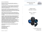
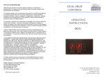
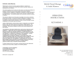
Infrared Radiant Heaters and Controls
N112 W14600 Mequon Road · Germantown, WI 53022 · 1-800-774-4450 · www.electricheat.com
Table of Contents
General Information
About Radiant Electric Heat
Eastern Edison Company
Case Study - Apartments/Key Benefits
of Radiant Electric Heating
Case Study - Commerical/Hot Yoga
Installation Examples
..............................
..............................
..............................
3
4
5
..............................
..............................
6
7
..............................
..............................
..............................
..............................
8,9
10,11
12,13
18
Products
1624CL Drop-In Ceiling Panel
Cove Mounting
Baseboard Mounting
Thermostats and Options
Specifications/Warranty
Heat Loss Questions
Three-Part Specification
Warranty Information
..............................
..............................
..............................
14
15,16,17
18
About REH
Radiant Electric Heat (REH) is headquartered in
Germantown, Wisconsin. At REH, we manufacture
CeramiCircuitTM infrared radiant electric heating panels
which have been the quality standard in the industry for
over half a century.
Today there are a lot of options in the HVAC industry on
how best to create a thermally comfortable environment
that is also energy efficient, environmentally friendly
and cost effective. Our infrared heating panels are the
solution to all four in nearly unequalled fashion.
Our products include a wide variety of baseboard, cove
and ceiling radiant heating systems which have proven
to be cost effective and service-superior over decades
of use. REH products are suitable for residential,
commercial, institutional and industrial applications.
It is a product that not only competes with many of its
HVAC counterparts; in application after application it
outperforms them in all four of the above mentioned
areas. Whether it is commercial, institutional, residential
or industrial, there is not a convective system in
existence that can match the efficiency of REH’s infrared
radiant panels.
In many installations, CeramiCircuit panels have
produced energy savings of up to 73% over more
conventional heating systems; equally impressive
are the savings in carbon emissions. By applying the
concept of radiant heating well before most others,
Radiant Electric Heat has been a leader in technology
and innovation in the energy conservation segment of
the heating industry since 1948.
The REH staff is committed to carrying forward our
founders pioneering work while delivering a level of
quality and customer service that is unequaled in
the industry.
Page 3
Eastern Edison Company
* REH Installed Product
Page 4
Apartment Savings
The Superior Choice for
Multi-family Structures
Lower Electric Bills
No Seasonal Maintenance
OLD CONVECTIVE HEATING
RESIDENCES
UNITS PER RESIDENCE
KWH/YEAR
KWH UNIT AVERAGE
Tobin Towers
Quincy Housing Authority
85 Clay St., Quincy, MA
200
3,399,500
16,998
Marlboro Housing Authority
Main & Newton Streets
Marlboro, MA
125
1,674,300
13,395
Northampton Housing Authority
Gonz St., Northampton, MA
192
12,353
2,371,800
TOTALS
Convective Heating
517 Residences
7,445,600 KWH
14,401 KWH
Average per Residence
NEW CERAMICIRCUIT HEATING
RESIDENCES
UNITS PER RESIDENCE
KWH/YEAR
KWH UNIT AVERAGE
Ocean View
Quincy Housing Authority
73 Bicknell St., Quincy, MA
275
3,062,250
11,135
Pagnano Tower
Quincy Housing Authority
109 Curtis Ave., Quincy, MA
165
1,725,000
10,455
Sawyer Tower
Quincy Housing Authority
95 Martensen St., Quincy, MA
150
1,642,500
10,950
TOTALS
CeramicircuitTM Heaters
590 Residences
6,429,750 KWH
10,898 KWH
Average per Residence
*One bedroom units average size of 480 sq. ft. Savings based on current Con Edison rate of $0.1673 per KWH as of 10/2009
3,503 KWH saved per unit
in one heating season
$586.00 average single unit
savings in one heating seasion
$345,740 TOTAL savings on
590 units in one heating season
Key Benefits of Radiant Electric Heating
• Save up to 73% in energy costs over other traditional
heating methods.
• Simple low cost installation.
• Comfortable at lower thermostat settings; heats people
first then the air.
• Room by room zone control provides economical
comfort only where you need it.
• Works great with setback thermostats; rapid recovery
times raise temperatures into your comfort zone in
minutes not hours.
• Reduce carbon emissions; most of all when replacing
direct-fired gas heating units in industrial, warehouse
and garage applications.
• No future maintenance expense, no service
requirements, no filters to replace and no inspections.
• Reliable – Many of our panels are still providing
comfort after 62 years of service.
• Extremely clean with zero emissions; no danger of
asphyxiation and perfect for those with allergies and/or
chemical sensitivities.
• Low operating temperature eliminates the risk of fires.
• Perfect for new construction, remodeling, additions,
basement recreation rooms, garages and workshops.
• Suitable for residential, commercial, medical and
industrial applications.
• Radiant Electric Heat produces its infrared radiant
panels in a state of the art, low-impact, environmentally
clean manufacturing facility.
Page 5
Riveredge Country Club - Marshfield, WI
Riveredge Country Club is a 6,400 Sq.Ft
restaurant, bar and banquet facility that
was heated with a propane fired*, ducted,
forced air heating system and converted
to CeramiCircuitTM Radiant Electric Heat
Model 945 and 1445 Cove Panels.
Installation Details and Customer Savings
· (40) 945C 1,000 Watt Units
· (7) 1445C 1,500 Watt Units
· Installed at 7.89 Watts per square foot
· $96.77 Average Energy Cost Per Day With Old
Forced Air System
· $25.81 Average Energy Cost Per Day With New
CeramiCircuit Radiant Electric Heating System
· $10,644 SAVINGS Per Heating Season
*NOTE: If the original heating system was a natural gas fired furnace, the
seasonal savings with the REH cove heaters would have been $7,294.
CeramiCircuit™ and Hot Yoga
When you are in a traditional Hot Yoga studio or Sauna,
you are in a room with very hot, circulating air. When in a
studio heated by a CeramiCircuit infrared heating
system, the infrared heat penetrates and warms your
body, eliminating the scorching, drying effect of moving
air which is inherent in all convective heating systems.
This warming effect on your body stimulates your
cardiovascular system. It is no surprise that Yoga studios
all over the country are turning to Radiant Electric Heat
CeramiCircuit Infrared Heating Systems to safely,
efficiently and cost effectively heat up their sessions.
Benefits of Hot Yoga using CeramicCircuit
Infrared Heat
• Achieve and maintain high temperatures at a fraction
of the cost of other HVAC systems.
• Burns hundreds of calories.
• Strengthens the cardiovascular system.
• Eases joint pain and stiffness while relaxing muscles
and increasing flexibility.1
Page 6
SM Fortney, and NB Vroman, “Exercise, performance and
temperature control: temperature regulation during exercise
and implications for sports performance and training.” (1985),
http://www.ncbi.nlm.nih.gov/pubmed/3883461 (Mar 30 2012).
1
Installation Examples
Arlington Housing Authority; Arlington, MA
Ashtabula Housing Authority; Ashtabula, OH
Bridgewater Housing Authority; Bridgewater, MA
Burlington Housing Authority; Burlington, MA
Center for Disability Services; Albany, NY
Cuyahoga Metropolitan Housing Authority; Cleveland, OH
Cytonet; Durham, NC
Department of Corrections; Trenton, NJ
First Evangelical Lutheran Church; Grand Rapids, MN
Flowers Essence Services; Nevada City, CA
Hampton Hotels; Horseheads, NY
Harbor Athletics; Madison, WI
Harvard University
Hot Yoga Helena; Helena, MT
Housing Authority of Elizabethtown; Elizabethtown, KY
Jersey Shore University Medical Center
King Country Housing Authority; Seattle, WA
Lighthouse Baptist Church; Holbrook, MA
Love Tabernacle; Milwaukee, WI
Mad Mex; Pittsburgh, PA
Main Street Houses; South Fallsburg, NY
Montana State University
National Park Service
New London Housing Authority; New London, CT
Nordstrom; Irvine, CA
Osthoff House; Elkhart Lake, WI
Pennsylvania Trolley Museum; Washington, PA
Pizzas by Marchelloni; Fairbury, IL
Plum Healthcare Group; San Marcos, CA
Red Root Hot Yoga; Davenport, IA
Riveredge Country Club; Marshfield, WI
San Francisco Airport Commission; San Francisco, CA
St Joseph Church; Providence, RI
Stanford University
State University of New York
Studio Bikram Walnut Creek; Piedmont, CA
Sunoco Refining Supply; Philadelphia, PA
Taylor Design Healthy Homes; Townshend, VT
The Athletic Club; Guelph, ON
TJC and Associates, Inc; Oakland, CA
University of Alaska – Fairbanks
University of California – San Diego, - Riverside, - Berkeley
University of Ohio – Miami
University of Rhode Island
US Geological Survey
Valley View Nursing Home; Frenchtown, NJ
Vernon Housing Authority; Vernon, CT
Waterfront Restaurant; San Francisco, CA
Westerly Housing Authority; Westerly, RI
Weston Community Housing; Weston, MA
Wisconsin Stamping; Germantown, WI
YMCA; Metuchen, NJ
Cove Installation
TJC and Associates, Inc; Oakland, CA
Wisconsin Stamping, Germantown, WI
Page 7
1624 CL - Drop-In Ceiling Panel
Wall
Model
Watts
W
1624CL
625
23.75"
L
23.75"
H1
H2
H3
1.17"
2.67"
3.13"
Thermostat
Power
Supply
L1
Blk
L2
Wht
T
GRN-Ground
Wiring Diagram
Grounding
Point
Heating Element
Scan to download
this document
Page 8
IMPORTANT INSTRUCTIONS
When using electrical appliances, basic precautions
should always be followed to reduce the risk of fire, electric shock, and injury to persons, including the following:
1. Read all instructions before using this heater.
2. This heater is hot when in use. To avoid burns, do
not let bare skin touch hot surfaces. Keep combustible
materials, such as furniture, pillows, bedding, papers,
clothes, etc. and curtains at least 3 feet (0.9 m) from
the front of the heater and keep them away from the
sides and rear.
3. Extreme caution is necessary when any heater is used
by or near children or invalids and whenever the
heater is left operating and unattended.
4. Do not operate any heater after it malfunctions.
Disconnect power at service panel and have heater
inspected by a reputable electrician before reusing.
5. Do not use outdoors.
6. To disconnect heater, turn controls to off, and turn off
power to heater circuit at main disconnect panel.
7. Do not insert or allow foreign objects to enter any
ventilation or exhaust opening as this may cause an
electric shock or fire, or damage the heater.
8. To prevent a possible fire, do not block air intakes or
exhaust in any manner.
9. A heater has hot and arcing or sparking parts inside.
Do not use it in areas where gasoline, paint, or
flammable vapors or liquids are used or stored.
Use this heater only as described in this manual. Any
other use not recommended by the manufacturer may
cause fire, electric shock, or injury to persons.
SAVE THESE INSTRUCTIONS
Construction
Heating Elements: Porcelain enamel coated 18
gauge steel plate, with energizing ceramic circuit on
internal face of heating element; minimum 1.7 Watts per
square inch of emissive surface area.
Heater Body: 20 gauge steel, high-temperature
resistant powder coating. Provided with manufacturer’s
standard 1.5 foot leads, high density foil backed
insulation, enclosure, and junction box.
Accessories: Provide as indicated, thermostat and
NEMA 1 Enclosure control panel for models specified.
Installation: Install heating units where indicated,
in accordance with manufacturer’s written instructions,
applicable requirements of IEC, in compliance with
recognized industry practices to ensure products fulfill
requirements. Top of heater unit and trim shall be level.
Where heating units are mounted adjacent to each other,
the top edges shall be at the same height.
Maintenance Instructions
Maintenance of your CeramiCircuit™ heater is not
needed, though you may want to clean it as necessary.
The user can perform cleaning. All other servicing is to
be done by qualified service personnel.
1.
2.
3.
4.
Turn off the power at the circuit breaker panel
Wait for the heating element to cool.
Clean area with a dry cloth.
Restore power.
Operating Instructions
1. Heater must be properly installed before it is used.
2. Refer to the thermostat or controller’s operating
instructions for proper usage.
INSTALLATION INSTRUCTIONS
Heaters are hard wired directly to the electrical main.
Junction boxes are not required except as indicated by
local code or inspection requirements. Wiring procedures
and connections should be in accordance with the
National Electric Code (NEC) and local codes.
Connection box is 4.62 in3 (75.69 cm3).
To reduce the risk of fire, do not store or use gasoline or
other flammable vapors and liquids in the vicinity of the
heater. CAUTION - High temperature. Keep electrical
cords, drapes, and other furnishings away from heater.
Grounding is required for each heater. Remove all
construction debris (plaster, sawdust, etc) from interior
and exterior of the heater. Do not install heaters against
combustible low density cellulose fiberboard surfaces.
Heaters are not to be placed below an electrical
convenience receptacle. Install heater at least 6 inches
(15.24 cm) from drapes.
1. Remove all packing material.
2. Place heater assembly in suspension grid.
3. Secure according to local building and electrical
codes.
4. Attach grounding wire to ground screw on the
flange tab.
5. Connect mains to heater lead wires.
6. Check tightness of all electrical connections. Inspect
all connections for short circuits.
Page 9
Cove Mounting
TOP VIEW
D
MOUNTING SLOTS
H
BACK VIEW
Cove
Model
Watts
L
H
W
D
632C
645C
945C
1445C
585
825
1000
1500
33"
46"
46"
46"
7"
7"
10"
15"
1.125"
1.125"
1.125"
1.125"
5.5"
5.5"
7.5"
10"
Thermostat
Power
Supply
L1
Blk
L2
Wht
T
GRN-Ground
Wiring Diagram
Grounding
Point
Heating Element
Scan to download
this document
Page 10
IMPORTANT INSTRUCTIONS
When using electrical appliances, basic precautions
should always be followed to reduce the risk of fire, electric shock, and injury to persons, including the following:
1. Read all instructions before using this heater.
2. This heater is hot when in use. To avoid burns, do
not let bare skin touch hot surfaces. Keep combustible materials, such as furniture, pillows, bedding,
papers, clothes, etc. and curtains at least 3 feet
(0.9 m) from the front of the heater and keep them
away from the sides and rear.
3. Extreme caution is necessary when any heater is
used by or near children or invalids and whenever the
heater is left operating and unattended.
4. Do not operate any heater after it malfunctions.
Disconnect power at service panel and have heater
inspected by a reputable electrician before reusing.
5. Do not use outdoors.
6. To disconnect heater, turn controls to off, and turn off
power to heater circuit at main disconnect panel.
7. Do not insert or allow foreign objects to enter any
ventilation or exhaust opening as this may cause an
electric shock or fire, or damage the heater.
8. To prevent a possible fire, do not block air intakes or
exhaust in any manner.
9. A heater has hot and arcing or sparking parts inside.
Do not use it in areas where gasoline, paint, or
flammable vapors or liquids are used or stored.
Use this heater only as described in this manual. Any
other use not recommended by the manufacturer may
cause fire, electric shock, or injury to persons.
SAVE THESE INSTRUCTIONS
Construction
Heating Elements: Porcelain enamel coated 18 gauge
steel plate, with energizing ceramic circuit on internal face
of heating element; minimum 2.3 Watts per square inch of
emissive surface area.
Heater Body: 20 gauge steel, high-temperature resistant
powder coating. Provided with manufacturer’s standard 7/8
inch knockouts for power feed.
Accessories: Provide as indicated, thermostat, NEMA 1
Enclosure control panel, and mounting brackets for models
specified.
Installation: Install heating units where indicated, in
accordance with manufacturer’s written instructions,
applicable requirements of IEC, in compliance with
recognized industry practices to ensure products fulfill
requirements. Secure in place with mounting brackets. Top
of heater unit and trim shall be level. Where heating units
are mounted adjacent to each other, the top edges shall be
at the same height.
Maintenance Instructions
Maintenance of your CeramiCircuit™ heater is not needed,
though you may want to clean it as necessary. The user
can perform cleaning. All other servicing is to be done by
qualified service personnel.
1. Turn off the power at the circuit breaker panel
2. Wait for the heating element to cool.
3. Clean area with a dry cloth.
4. Restore power.
Operating Instructions
1. Heater must be properly installed before it is used.
2. Refer to the thermostat or controller’s operating
instructions for proper usage.
INSTALLATION INSTRUCTIONS
Heaters are not to be placed below an electrical convenience receptacle. Heaters produce high temperatures.
Keep electrical cords, drapes, and other furnishings away
from heaters. Do not store gasoline or flammable solvents in
the vicinity of these heaters.
Installation Warnings - For supply connections use wires
suitable for at least 194° F (90° C). Grounding is required
for each heater. Remove all construction debris (plaster,
sawdust, etc.) from interior and exterior of the heater. Do not
install heaters against paperboard or low density surfaces.
Mounting Instructions - Heaters are hard wired directly to
the electrical main. Junction boxes are not required except
as indicated by local code or inspection requirements. Install
on studs or finished wall. Do not install less than 6 feet
(1.8 m) from the floor and closer than 6 inches (152.4 mm)
from vertical or horizontal surfaces.
1. Locate and level mounting brackets on studs or finished
wall, taking into account the minimum clearances from
vertical and horizontal surfaces.
2. Lay heating unit face down on a solid and protective
surface to prevent scratching. Remove wire channel from
rear of heater. Determine which raceway knockout will be
used for electrical mains, knock plug out, run mains
through hole and make connections according to code.
3. Hang the bottom edge of the heater on the bottom ends
of the mounting brackets using the narrow slots in the
edge of the heater. Do not use the wide slots for
mounting.
4. Thread the electrical mains through the clamp in the
raceway.
5. Attached the grounding wire to ground screw inside the
raceway.
6. Connect mains to heater lead wires. Connect ground wire
to threaded grounding screw. Check tightness of all
electrical connections and wire nuts. Inspect all
connections for short circuit.
7. Reattach raceway channel to rear of heater.
8. Attach end caps to heater.
9. Swing heater up and gently snap the top flanges into the
top edge of the heater.
10. Fasten heater to brackets by driving screw through the
pre-drilled holes.
Page 11
Baseboard Mounting
Base Enclosure
D
Reflector
L
Element
Spacer
H
Grill
Baseboard
Model
Watts
L
H
W
527B
545B
400
650
30.87"
48"
6.75"
6.75"
3.125"
3.125"
Thermostat
Power
Supply
L1
Blk
L2
Wht
T
GRN-Ground
Wiring Diagram
Grounding
Point
Heating Element
Scan to download
this document
Page 12
IMPORTANT INSTRUCTIONS
When using electrical appliances, basic precautions
should always be followed to reduce the risk of fire, electric shock, and injury to persons, including the following:
1. Read all instructions before using this heater.
2. A heater has hot and arcing or sparking parts inside.
Do not use it in areas where gasoline, paint, or
flammable liquids are used or stored.
3. This heater is hot when in use. To avoid burns, do not
let bare skin touch hot surfaces. Keep combustible
materials, such as furniture, pillows, bedding, papers,
clothes, and curtains away from heater.
4. Do not use on soft surfaces, like a bed, where
openings may become blocked.
5. Do not insert or allow foreign objects to enter any
openings as this may cause an electric shock or fire, or
damage to the heater.
SAVE THESE INSTRUCTIONS
Construction
Heating Elements: Porcelain enamel coated 18
gauge steel plate, with energizing ceramic circuit on
internal face of heating element; minimum 2.8 Watts per
square inch of emissive surface area.
Heater Body: 20 gauge steel, high-temperature
resistant powder coating. Provided with manufacturer’s
standard 7/8 inch knockouts for power feed.
Accessories: Provide as indicated, thermostat,
NEMA 1 Enclosure control panel, and protective grill for
models specified.
Installation: Install heating units where indicated,
in accordance with manufacturer’s written instructions,
applicable requirements of IEC, in compliance with
recognized industry practices to ensure products fulfill
requirements. Top of heater unit and trim shall be level.
Where heating units are mounted adjacent to each other,
the top edges shall be at the same height.
Maintenance Instructions
Maintenance of your CeramiCircuit™ heater is not
needed, though you may want to clean it as necessary.
The user can perform cleaning. All other servicing is to be
done by qualified service personnel.
1.
2.
3.
4.
5.
6.
Turn off the power at the circuit breaker panel
Wait for the heating element to cool.
Remove grill.
Clean area with a dry cloth.
Replace grill.
Restore power.
Operating Instructions
1. Heater must be properly installed before it is used.
2. Refer to the thermostat or controller’s operating
instructions for proper usage.
INSTALLATION INSTRUCTIONS
Heaters are hard wired directly to the electrical main.
Junction boxes are not required except as indicated by
local code or inspection requirements. Wiring procedures
and connections should be in accordance with the
National Electric Code (NEC) and local codes.
To reduce the risk of fire, do not store or use gasoline or
other flammable vapors and liquids in the vicinity of the
heater. Install on studs or finished wall. Height from rough
floor to bottom of heater must be a minimum of 1-1/2
inches (3/4 inches from finished).
CAUTION - High temperature. Keep electrical cords,
drapes, and other furnishings away from heater.
Grounding is required for each heater. Remove all
construction debris (plaster, sawdust, etc) from interior
and exterior of the heater. Do not install heaters against
combustible low density cellulose fiberboard surfaces.
Heaters are not to be placed below an electrical
convenience receptacle. Install heater at least 6 inches
below drapes.
1. Remove all packing material.
2. Remove grill cover from unit.
3. Remove heating element by removing only the center
screws from the left and right sides. Note; use caution
when handling the heating element so the electrical
circuit is not scratched, or the soldered wire leads are
not damaged.
4. Knockout hole for wire and insert wire clamp.
5. Locate the unit on the wall and level. The unit can be
secured by screws direct into wall studs or into dry
wall using suitable wall anchors.
6. Fish wire through clamp and make connections per
diagram. Again, use caution in handling the element to
avoid damaging the heater circuit.
7. After wire connections are complete and secure,
re-fasten the heating element with the two screws
removed in step 3. Be sure the wires are not being
pinched while re-installing the element.
8. Replace grill.
Page 13
Room 3
Room 4
Room 5
Room 6
Room 7
Heat Loss Questions
Room 2
Name:
Phone:
City, State of job:
Will infrared heat be the primary or supplemental source?
Room 1
Dimensions (Measured in feet)
Length
Width
Ceiling Height
Exterior walls
Building material
Insulation Values (If R-value if known or list material and inches)
Walls
Floor
Ceiling
Windows
Quantity
Length
Width
U-value or Type
Doors opening to outside
Quantity
Length
Width
Type
Heated Space
Above and/or Below?
Room 8
Room 9
Room 10
Page 14
Scan to download
this document
Three Part Specification
SECTION 238330 – RADIANT HEATING UNITS
PART 1 - GENERAL
1.1
SUMMARY
A. Section Includes: High efficiency infrared radiant panel heaters for:
[portable] [cove] [wall] [ceiling] [baseboard] mounting.
B. Related Sections
1. Division 00 – General and Supplementary Conditions.
2. Division 26 – Electrical: Wiring.
C. References
1. Underwriters Laboratory (UL)
2. National Electrical Manufacturers Association (NEMA)
3. International Electrical Code (IEC)
D. Drawings, the provisions of the Agreement, the General Conditions, and Division 1 specification sections
apply to all work of this Section.
E. Substitutions: ***One of the following***
1. [Substitutions will be considered only under the terms and conditions of Section 016000.]
2. [Substitutions not allowed.]
1.2
SUBMITTALS
A. Make submittals in accordance with Section 013300.
B. Product Data: Manufacturer’s complete product data including wiring support diagram, switching, heater
size and wattage, and color selector.
C. Warranty: A sample copy of the Manufacturer warranty for the periods stipulated. Each specimen must be
a preprinted representative sample of the issuing company’s standard warranty for the units specified.
D. Certification: Documentation demonstrating UL listing.
1.3
DESIGN REQUIREMENTS
A. Radiant heater units shall be ceramic circuit radiant panel type using porcelain enamel-coated steel plate.
Calrod- or filament-type radiant heaters are not acceptable.
1.4
QUALITY ASSURANCE
A. Manufacturer: Company specializing in the manufacture of ceramic circuit radiant panel heaters.
B. Installer: Hard-wired units shall be installed by a licensed electrician as applicable to the jurisdiction.
1.5
REGULATORY REQUIREMENTS
A. Conform to applicable building and jurisdictional codes for installation of heaters.
1.6
DELIVERY, STORAGE, AND PROTECTION
A. In accordance with Section 016000.
B. The Contractor together with the Owner or his designated Representative shall designate a storage area
for all components. The area shall be cool, dry, out of direct sunlight, and in accordance with
manufacturer’s recommendations and relevant regulatory agencies. Materials shall not be stored in
quantities that will exceed design loads, damage substrate materials, or hinder installation.
1.7
ENVIRONMENTAL REQUIREMENTS
A. Do not install heaters until building is enclosed, dust- or moisture-generating activities
have terminated, and substrates have been finished as specified.
B. Ensure that substrate materials are dry and free of contaminants. Do not commence
with the installation unless substrate conditions are suitable. Contractor shall
demonstrate that substrate conditions are suitable for the installation of the units.
1.8
COORDINATION & PROTECTION
A. Coordinate the work with the installation of associated wiring, panels, switches,
and accessories, as the work of this section proceeds.
Scan to download
this document
Page 15
SECTION 238330 – RADIANT HEATING UNITS
1.9
WARRANTY
A. In accordance with Section 017700.
B. Manufacturer’s Limited Warranty: Provide 10 year manufacturer’s limited warranty under provisions of this
section. This warranty provides for replacement of failed heating element to the original owner for a period
of 10 years from the date of purchase.
PART 2 - PRODUCT
Use the next Article and one or more of the following 6 Articles for Proprietary Specification
2.1
MANUFACTURER
A. Radiant Electric Heat (Germantown, WI; 800-774-4450).
2.2
PORTABLE INFRARED CERAMIC PANEL HEATER
A. [Model “1624;” standard black finish] [Model “1624SS;” stainless steel finish]; 1,000 Watts.
B. Provide with thermostat and safety tip-over switch.
C. Provide with wheels affixed to units.
D. Plug-in installation.
2.3
COVE-MOUNT INFRARED CERAMIC PANEL HEATER
A. [Model “1445C”, 1500 Watts] [Model “945C”, 1,000 Watts] [Model “645C”, 825 Watts]
[Model “632C”, 585 Watts]
B. [120] [208] [240] [277] Volt.
C. Color: [Beige] [White] [Custom].
D. Option: Integrated thermostat.
E. For [plug-in] [hard-wire] installation.
2.4
WALL-MOUNT INFRARED CERAMIC PANEL HEATER
A. [Model “1445W”, 1,500 Watts] [Model “945W”, 1,000 Watts].
B. [120] [208] [240] [277] Volt.
C. Color: [Beige] [White] [Custom].
D. Option: Integrated thermostat.
E. For [plug-in] [hard-wire] installation.
2.5
CEILING LAY-IN-MOUNT INFRARED CERAMIC PANEL HEATER
A. [Model “1624CL”, 625 Watts].
B. [120] [208] [240] [277] Volt.
C. Color: [White] [Custom].
D. For [plug-in] [hard-wire] installation.
2.6
CEILING SURFACE-MOUNT INFRARED CERAMIC PANEL HEATER
A. [Model “1445CL”, 1,500 Watts] [Model “945CL”, 1,000 Watts].
B. [120] [208] [240] [277] Volt.
C. Color: [Beige] [White] [Custom].
D. For [plug-in] [hard-wire] installation.
2.7
BASEBOARD-MOUNT INFRARED CERAMIC PANEL HEATER
A. [Model “545B”, 650 Watts] [Model “527B”, 400 Watts]
B. [120] [208] [240] [277] Volt.
C. Color: [Beige] [White] [Custom].
D. Internal temperature limit switch.
E. Option: Integrated thermostat.
F. For [plug-in] [hard-wire] installation.
Page 16
SECTION 238330 – RADIANT HEATING UNITS
2.8
ACCESSORIES
A. Thermostat: [Programmable] [Non-Programmable] [Digital Readout] [Line Voltage]
B. Control Panel: NEMA 1 Enclosure; UL listed; 120 Volt control circuit.
C. Mounting Brackets: As standard for type of unit specified.
Use the next Article for Descriptive or Performance Specification
2.9
INFRARED CERAMIC PANEL HEATER
A. Heating Elements:
1. Porcelain enamel coated 18 gauge steel plate
2. Energizing ceramic circuit on internal face of heating element
3. Wattage density: Minimum 2.3 Watts per square inch of emissive surface area.
B. Heater Body:
1. 20 gauge steel, high-temperature resistant powder coating.
2. Provide manufacturer’s standard 7/8 inch knockouts for power feed.
3. Provide heater body safety grill as standard with type of unit specified.
C. Design: [Portable] [Ceiling Cove-Mounted] [Wall-Mounted] [Baseboard-Mounted] type.
D. Wattage: ***Select one or more of the following***
1. ***for Portable Heaters*** 1,000 Watts
2. ***for Ceiling Cove Mount Heaters*** [1,500 Watts] [1,000 Watts] [825 Watts] [585 Watts]
3. ***for Wall or Ceiling Mount Heaters*** [1,500 Watts] [1,000 Watts]
4. ***for Baseboard Mount Heaters*** [650 Watts] [400 Watts]
E. Voltage: [120] [208] [240] [277] Volt.
F. For [plug-in] [hard-wire] installation.
G. Accessories:
1. Thermostat: [Programmable] [Non-Programmable] [Digital Readout] [Line Voltage]
2. Control Panel: NEMA 1 Enclosure; UL listed; 120 Volt control circuit.
3. Mounting Brackets: As standard for type of unit specified.
PART 3 - EXECUTION
3.1
EXAMINATION
A. Prior to starting work, carefully inspect installed work of other trades and verify that such work is complete
to the point where work of this Section may properly commence. Notify the Architect in writing of
conditions detrimental to the proper and timely completion of the work.
B. Do not begin installation until all unsatisfactory conditions are resolved. Beginning work constitutes
acceptance of site conditions and responsibility for defective installation caused by prior observable
conditions.
3.2
PREPARATION
A. Coordinate the location of heating units with other work. Ensure units are located to accommodate fittings
and units of equipment which are to be placed after the installation of heating units.
3.3
INSTALLATION
A. General: Install heating units where indicated, in accordance with manufacturer’s written instructions,
applicable requirements of IEC, in compliance with recognized industry practices to ensure products
fulfill requirements.
B. Secure in place with mounting brackets or by fastening back panel of unit to wall, as applicable to type of
model specified, unless otherwise noted. Top of heater unit and trim shall be level. Firmly anchor heating
units directly or with concealed bracing to building structure. Where heating units are mounted adjacent to
each other, the top edges shall be at the same height.
3.4
TESTING
A. Provide testing as required by Division [00] [23] [26].
Page 17
Available Options
Line Voltage Thermostats
Control Panels
Color Matching
Moisture Protection
Stainless Steel Frames and Enclosures
Corporate Branded Elements
10-Year Limited Warranty
Radiant Electric Heat warrants its heating elements against all defects
in materials and workmanship for a period of 10 years from the date of
purchase, subject to the following terms and conditions:
This warranty applies only for normal use of the product, and shall not
be effective for products or parts which do not function properly due to
misuse, alteration, installation, accident, negligence, misapplication,
modification, improper installation (including improper operating voltage)
or maintenance, or if any product or part has been serviced or repaired
by other than Radiant Electric Heat. This warranty extends only to the
end user or consumer and does not extend to retailers.
This warranty is effective only if the product is operated in the country
for which it was manufactured and into which it was sold and
purchased. A product that requires modifications or adoption to enable
it to operate in any other country than the country for which it was
designed, manufactured, approved and/or authorized, or repair of
products damaged by these modifications is not covered under
this warranty.
Liability of Radiant Electric Heat shall be limited to repair or replacement
of any defective product or part that has been returned to Radiant
Electric Heat for evaluation, which option shall be the sole decision of
Radiant Electric Heat. This warranty is effective only on behalf of the
original owner of the product and is not transferable. This warranty is
effective only if the user manual instructions have been followed.
Page 18
THE WARRANTY PROVIDED HEREIN SHALL BE THE SOLE AND
EXCLUSIVE WARRANTY. THERE SHALL BE NO OTHER
WARRANTIES EXPRESS OR IMPLIED INCLUDING ANY IMPLIED
WARRANTY OF MERCHANTABILITY OR FITNESS OR ANY OTHER
OBLIGATION ON THE PART OF RADIANT ELECTRIC HEAT WITH
RESPECT TO PRODUCTS COVERED BY THIS WARRANTY.
RADIANT ELECTRIC HEAT SHALL HAVE NO LIABILITY FOR ANY
INCIDENTAL, CONSEQUENTIAL OR SPECIAL DAMAGES. IN NO
EVENT SHALL THIS WARRANTY REQUIRE MORE THAN THE
REPAIR OR REPLACEMENT OF ANY PART OR PARTS WHICH
ARE FOUND TO BE DEFECTIVE WITHIN THE EFFECTIVE
PERIOD OF THE WARRANTY. NO REFUNDS WILL BE GIVEN. IF
REPLACEMENT PARTS FOR DEFECTIVE MATERIALS ARE NOT
AVAILABLE, RADIANT ELECTRIC HEAT RESERVES THE RIGHT
TO MAKE PRODUCT SUBSTITUTIONS IN LIEU OF REPAIR OR
REPLACEMENT.
To obtain warranty service on this product contact Radiant Electric Heat
or mail the product and your dated sales receipt (as proof of purchase),
postpaid, to the following address:
Radiant Electric Heat
N112W14600 Mequon Road
Germantown, WI 53022
888-774-4450
No COD’s will be accepted.
All specifications subject to change without notice.
Notes
Page 19
N112 W14600 Mequon Road
Germantown, WI 53022
(P) 800-774-4450
(F) 262-502-1282
www.electricheat.com
1201PE01