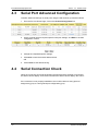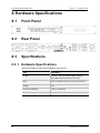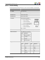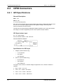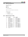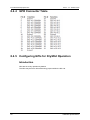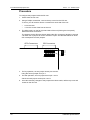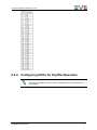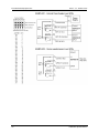
1
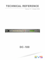
TECHNICAL REFERENCE Version 1.1 – October 2014 DC-100 Technical Reference Manual DC-100 1.1 Copyright EVS Broadcast Equipment – Copyright © 2014. All rights reserved. Disclaimer The information in this manual is furnished for informational use only and subject to change without notice. While every effort has been made to ensure that the information contained in this user manual is accurate, up-to-date and reliable, EVS Broadcast Equipment cannot be held responsible for inaccuracies or errors that may appear in this publication. Improvement Requests Your comments will help us improve the quality of the user documentation. Do not hesitate to send improvement requests, or report any error or inaccuracy on this user manual by e-mail to [email protected]. Regional Contacts The address and phone number of the EVS headquarters are usually mentioned in the Help > About menu in the user interface. You will find the full list of addresses and phone numbers of local offices either at the end of this user manual (for manuals on hardware products) or on the EVS website on the following page: http://www.evs.com/contacts. User Manuals on EVS Website The latest version of the user manual, if any, and other user manuals on EVS products can be found on the EVS download center, on the following webpage: http://www.evs.com/downloadcenter. I Technical Reference Manual DC-100 1.1 Table of Contents TABLE OF CONTENTS ............................................................................ III 1. INTRODUCTION ................................................................................. 1 2. INSTALLATION................................................................................... 2 3. NETWORK CONFIGURATION ........................................................... 3 3.1 Setting up the IP Address ..........................................................................................3 3.2 Setting up the Subnet Mask.......................................................................................3 3.3 Setting up the Gateway Address ...............................................................................3 3.4 Ethernet Link Speed Setup ........................................................................................4 4. SYSTEM CONFIGURATION ............................................................... 5 4.1 Introduction ................................................................................................................5 4.2 Switcher Protocol Configuration.................................................................................5 4.2.1 Introduction ....................................................................................................5 4.2.2 EVS XML Protocol .........................................................................................6 4.2.3 Sony™ MVS ..................................................................................................7 4.2.4 Snell™ Kahuna ............................................................................................10 4.2.5 Grass Valley™ Kayak ..................................................................................11 4.2.6 Grass Valley™ Kalypso ...............................................................................12 4.2.7 Ross Video™ Vision ....................................................................................13 4.2.8 Grass Valley™ Kayenne/Karrera .................................................................14 4.2.9 GPI ..............................................................................................................15 4.3 Serial Port Advanced Configuration .........................................................................16 4.4 Serial Connection Check .........................................................................................16 5. ADVANCED SYSTEM CONFIGURATION ........................................ 17 5.1 Setting the Password ...............................................................................................17 5.2 Setting the System Label .........................................................................................17 5.3 Setting the System Time..........................................................................................18 6. FIRMWARE UPGRADE .................................................................... 19 6.1 Prerequisites............................................................................................................19 6.2 Procedure ................................................................................................................19 6.3 Illustrated Procedure ...............................................................................................20 6.4 FPGA Upgrade Procedure .......................................................................................21 7. Table of Contents EVENT LOGGING ............................................................................. 22 III EVS Broadcast Equipment S.A. Issue 1.1.A - October 2014 7.1 Overview .................................................................................................................22 7.2 Viewing and Saving Log Files ..................................................................................22 7.3 Deleting Log Files ....................................................................................................22 7.4 Changing Maximum Number of Log Files per Day ..................................................23 8. HARDWARE SPECIFICATIONS....................................................... 24 8.1 Front Panel ..............................................................................................................24 8.2 Rear Panel ..............................................................................................................24 8.3 Specifications ..........................................................................................................24 8.3.1 Hardware Specifications ..............................................................................24 8.3.2 Connectivity .................................................................................................25 8.4 GPIO Connectors ....................................................................................................26 8.4.1 GPI Specifications .......................................................................................26 8.4.2 GPO specifications ......................................................................................27 8.4.3 GPI Connector Table ...................................................................................27 8.4.4 GPO Connector Table .................................................................................28 8.4.5 Configuring GPIs for Dry/Wet Operation ......................................................28 8.4.6 Configuring GPOs for Dry/Wet Operation ....................................................31 IV Table of Contents Technical Reference Manual DC-100 1.1 1. Introduction This document covers installation, configuration and administration tasks on the DC-100 hardware. This hardware is used as the Director’s Cut gateway between the switcher and the IPDirector hardware. It allows IPDirector to speak one language that virtualizes any switcher protocol. Introduction 1 EVS Broadcast Equipment S.A. 2. Issue 1.1.A - October 2014 Installation Warning Do NOT apply AC voltage to power supply and then connect power supply to DC-100. Component damage may occur. To install and cable the DC-100, proceed as follows: 1. Connect the Cat 5 cable to the DC-100 connector labeled “E-NET #1”. Connect the other end of the Cat 5 cable to the supplied Ethernet hub. 2. Connect the power supply’s round locking female connector to the DC-100 connector labeled “POWER”. 3. Connect the female side of the power cable to the supplied power supply. 4. Connect the male side of the power cable to AC voltage, 100 – 240. 5. Push DC-100 power switch, located on front panel, to ON position. o “O” on power switch is on OFF position. o The Front panel LEDs will flash during power up. After power-up and system initialization, the front panel LEDs will turn off and the front panel display will show Model Number and Software Version. o Allow 25 seconds for power-up and system initialization to complete. o LTC connector is required. Refer to the hardware specification section. o Serial Port connectors are required depending switcher and protocols. Refer to the system configuration section. o No connection is required for the REF VIDEO, DIAGNOSTIC or VGA. 6. (Optional) Connect wired D37 connectors to the DC-100 connector labeled “GPI 116” and/or “GPI 17-32” to the switcher. Refer to the hardware specification section. 2 Installation Technical Reference Manual DC-100 1.1 3. Network Configuration Network configuration is required before system configuration. 3.1 Setting up the IP Address 1. On the DC-100 front panel, use the keys to select “Current IP”. 2. Press ENTER. The display will show the current IP address with the cursor in the far left column. 3. Use the keys to change the numbers. 4. Use the keys to move the cursor position. 5. Press ENTER to save the new IP address, or press ESC to exit without saving. Note The new IP address will take effect on the next power-up. 3.2 Setting up the Subnet Mask 1. On the DC-100 front panel, use the keys to select “Current Mask”. 2. Press ENTER. The display will show the current subnet mask with the cursor in the far left column. 3. Use the keys to change the numbers. 4. Use the keys to move the cursor position. 5. Press ENTER to save the new subnet mask, or press ESC to exit without saving. Note The new subnet mask will take effect on the next power-up. 3.3 Setting up the Gateway Address 1. On the DC-100 front panel, use the keys to select “Current Gateway”. 2. Press ENTER. The display will show the current gateway address with the cursor in the far left column. 3. Use the keys to change the numbers. 4. Use keys to move the cursor position. 5. Press ENTER to save new gateway address, or press ESC to exit without saving. Network Configuration 3 EVS Broadcast Equipment S.A. Issue 1.1.A - October 2014 Note The new gateway address will take effect on the next power-up. 3.4 Ethernet Link Speed Setup 1. On the DC-100 front panel, use the keys to select “Ethernet Status”. 2. Press ENTER. The display will show current the speed selection. 3. Use the keys to change the selection. 4. Select AUTO to use the highest available speed. 5. Select 10Mbs for long Ethernet cable runs. 6. Press ENTER to save new Ethernet link speed, or press ESC to exit without saving. Note The new Ethernet speed selection will take effect immediately. 4 Network Configuration Technical Reference Manual DC-100 1.1 4. System Configuration 4.1 Introduction System configuration is required after network configuration. The setup is performed using a computer running an off-the-shelf web browser such as Internet Explorer or Firefox. Connect the CAT5 cable from the computer to the same Ethernet switch to which the DC-100 is connected. After launching the web browser, enter the IP address of the DC-100 to be configured. The DC-100 Home Page will be displayed: 4.2 Switcher Protocol Configuration 4.2.1 Introduction Depending on the switcher model, one or several serial protocols need to be assigned to physical serial port(s) of the DC-100. Once a protocol is assigned, it will be configured using the default settings which are normally correct. Configuring the switcher protocol is only necessary if the production switcher does not use its default serial configuration for baud rate, parity, number of character bits or number of stop bits. In this case, refer to the section Serial port advanced configuration. Once a protocol is assigned, it will automatically try to connect to the device on the port it is connected to, and it will manage all communication automatically. No additional steps are required. An additional Ethernet XML protocol needs to be assigned for the DC-100 to be able to communicate with EVS software (ex: IPDirector Director’s Cut Gateway service). It will notify the EVS software of a change of source on the switcher’s program bus. Each notification will include all video sources currently selected on the program bus and a time stamp of when the change was reported by the production switcher. System Configuration 5 EVS Broadcast Equipment S.A. Issue 1.1.A - October 2014 4.2.2 EVS XML Protocol To assign the EVS XML protocol using the web browser, proceed as follows: 1. From the DC-100 Home Page, click the Protocol Assignment link. The following information is displayed: 2. Click the Edit Protocol Assignment Table link. The Protocol Assignment table opens in edit mode: 3. On Channel #4 line, select “Ethernet_1” in the Physical Connector column. 4. On Channel #4 line, select “evs_xml” in the Control Protocol column. 6 System Configuration Technical Reference Manual DC-100 1.1 5. (Optional) On Channel #4 line, edit Channel Label field as “EVS XML”. 6. Refer to next sections to select serial protocol according the switcher model. 4.2.3 Sony™ MVS To assign and configure the protocol using the web browser, proceed as follows: 1. From the DC-100 Home Page, click on the Protocol Assignment link. 2. Click on Edit Protocol Assignment Table link. 3. On Channel #1 line, select “Serial_1” in the Physical Connector column. 4. On Channel #1 line, select “mvs_tally” in the Control Protocol column. 5. (Optional) On Channel #1 line, edit Channel Label column field as “MVS TALLY”. 6. Click the Save button. 7. Reboot the DC-100. System Configuration 7 EVS Broadcast Equipment S.A. Issue 1.1.A - October 2014 On MVS Setup page 7333 (Switcher – Ouput): Identify the output number to be attached to the serial tally. Ex: Out# 1 for P/P PGM1 On MVS Setup page 7361 (Router/Tally - Router): Identify the source and destination number for the matrix. Ensure the output number to be attached to the serial tally must not be adjusted according the matrix. 8 System Configuration Technical Reference Manual DC-100 1.1 On MVS Setup page 7364 (Router/Tally - Tally Enable): If not existing, ensure to create a new entry that links the desired output number to a enabled tally type. Ex: OUT001 link to R1 On MVS Setup page 7367 (Router/Tally – Serial Tally): Select the Serial Tally Port and activate the corresponding tally group and type to be used. Ex: SCU Editor Panel Port assigned to R1 When using SCU Editor Port, ensure on page 7325 (Panel – Device Interface) that the “Editor Port Assign” is set to “Serial Tally”. System Configuration 9 EVS Broadcast Equipment S.A. Issue 1.1.A - October 2014 4.2.4 Snell™ Kahuna To assign and configure the protocol for the SnellTM Kahuna switcher using the web browser, proceed as follows: 1. From the DC-100 Home Page, click on the Protocol Assignment link. 2. Click on Edit Protocol Assignment Table link. 3. On Channel #1 line, select “Serial _1” in the Physical Connector column. 4. On Channel #1 line, select “kalypso_tally” in the Control Protocol column. 5. (optional) On Channel #1 line, edit Channel Label column field as “KALYPSO”. 6. On Channel #2 line, select “Serial _2” in the Physical Connector column. 7. On Channel #2 line, select “mvs_8000” in the Control Protocol column. 8. (Optional) On Channel #2 line, edit Channel Label column field as “MVS 8000”. 9. Click the Save button. 10. Reboot the DC-100. Known Issues: The Snell Kahuna uses kalypso_tally protocol and mvs_8000 protocol. The kalypso_tally protocol is used to receive tally information for what is on the Program bus. The mvs_8000 protocol is used to receive information about transitions from the switcher. In order for kalypso_tally protocol to report what is on the P/P Program bus to EVS_XML, output #1 must be used. Output #1 is the default P/P Program bus within the Kahuna switcher. The protocol assumes that output #1 is the P/P Program bus, and will not report tally information for any other outputs. At this time, the Snell Kahuna does not report information about transitions or keyers to the mvs_8000 protocol. This is an issue with the Kahuna itself, and not with the protocol or the DC-100. Kahuna 360 On the peripherals menu, the “Extension Enable“ needs to be set to OFF. The 360 is different than the normal Kahuna as it can link any ME to any Output; the highest ME has to be linked to the output 1 for the tally to react. 10 System Configuration Technical Reference Manual DC-100 1.1 4.2.5 Grass Valley™ Kayak To assign and configure the protocol for the Grass ValleyTM Kayak switcher using the web browser, proceed as follows: 1. From the DC-100 Home Page, click on the Protocol Assignment link. 2. Click on Edit Protocol Assignment Table link. 3. On Channel #1 line, select “Serial_1” in the Physical Connector column. 4. On Channel #1 line, select “gv_acos” in the Control Protocol column. 5. (optional) On Channel #1 line, edit Channel Label column field as “GV ACOS”. GV ACOS gv_acos 6. Click the Save button. 7. Reboot the DC-100. System Configuration 11 EVS Broadcast Equipment S.A. Issue 1.1.A - October 2014 4.2.6 Grass Valley™ Kalypso To assign and configure the protocol for the Grass ValleyTM Kalypso switcher using the web browser, proceed as follows: 1. From the DC-100 Home Page, click on the Protocol Assignment link. 2. Click on Edit Protocol Assignment Table link. 3. On Channel #1 line, select “Serial_1” in the Physical Connector column. 4. On Channel #1 line, select “kalypso_tally” in the Control Protocol column 5. (optional) On Channel #1 line, edit Channel Label column field as “KALYPSO” 6. Click the Save button. 7. Reboot the DC-100. Known Issues: Kalypso The Grass Valley Kalypso uses kalypso_tally protocol. This protocol is used to receive tally information for what is on the Program bus. In order for kalypso_tally protocol to report what is on the P/P Program bus to EVS_XML, output #1 must be used. Output #1 is the default P/P Program bus within the Kalypso switcher. The protocol assumes that output #1 is the P/P Program bus, and will not report tally information for any other outputs. The kalypso_tally protocol does not support the ability to receive information about transitions. Because only kalypso_tally protocol is supported on the Kalypso switcher, this information is unavailable. 12 System Configuration Technical Reference Manual DC-100 1.1 4.2.7 Ross Video™ Vision To assign and configure the protocol for the Ross VideoTM Vision switcher using the web browser, proceed as follows: 1. From the DC-100 Home Page, click on the Protocol Assignment link. 2. Click on Edit Protocol Assignment Table link. 3. On Channel #1 line, select “Serial_1” in the Physical Connector column. 4. On Channel #1 line, select “kalypso_tally” in the Control Protocol column 5. (optional) On Channel #1 line, edit Channel Label column field as “ROSS” 6. Click the Save button. 7. Reboot the DC-100. System Configuration 13 EVS Broadcast Equipment S.A. Issue 1.1.A - October 2014 4.2.8 Grass Valley™ Kayenne/Karrera To assign and configure the protocol for the Grass ValleyTM Kayenne/Karrera switcher using the web browser, proceed as follows: 1. From the DC-100 Home Page, click on the Protocol Assignment link. 2. Click on Edit Protocol Assignment Table link. 3. On Channel #1 line, select “Serial_1” in the Physical Connector column. 4. On Channel #1 line, select “kayenne_tally” in the Control Protocol column 5. (optional) On Channel #1 line, edit Channel Label column field as “KAYENNE” KAYENNE Kayenne_tally 6. Click the Save button. 7. Reboot the DC-100. Known Issues: Kayenne The Grass Valley Kayenne uses kalypso_tally protocol. This protocol is used to receive tally information for what is on the Program bus. The kalypso_tally protocol does not support the ability to receive information about transitions. Because only kalypso_tally protocol is supported on the Kalypso switcher, this information is unavailable. 14 System Configuration Technical Reference Manual DC-100 1.1 4.2.9 GPI To configure the GPI using the web browser, proceed as follows: 1. From the DC-100 Home Page, click on the Protocol Assignment link. 2. Click on Edit Protocol Assignment Table link. 3. On Channel #1 line, select “Serial_1” in the Physical Connector column. 4. On Channel #1 line, select “vtally” in the Control Protocol column 5. (optional) On Channel #1 line, edit “Channel Label” column field as “GPI V TALLY” 6. Click the Save button. 7. Reboot the DC-100. System Configuration 15 EVS Broadcast Equipment S.A. 4.3 Issue 1.1.A - October 2014 Serial Port Advanced Configuration To define advanced settings on serial ports using the web browser, proceed as follows: 1. From the DC-100 Home Page, click on the Protocol Assignment link. 2. On the channel line that requires specific serial port settings, click Edit on the PHY configuration column. 3. Change the requested specific settings. 4. Click Save to save the entered date and time. OR 5. Click Cancel to exit without saving. 4.4 Serial Connection Check When the connection and protocol between the DC100 and the switcher is successful, the status column display “Connected” otherwise the status column display “No Comm”. If the connection is not properly established, this could be either a wrong protocol assignment (§4.2) or a wrong serial port configuration (§4.3). 16 System Configuration Technical Reference Manual DC-100 1.1 5. Advanced System Configuration This chapter lists advanced system configuration that is not mandatory for a normal usage. 5.1 Setting the Password The default password, when shipped from the factory, is “controls” in lower case. The password is used to access all configuration screens. EVS does not advise to change the password in case remote or local assistance is needed. To modify the password using the web browser, proceed as follows: 1. From the DC-100 Home Page, click on the System Assignment link. The System page is displayed. 2. Click on Set Admin Password. The Set Password page will be displayed. 3. In the Old password entry box, type the current password. Note When shipped from the factory, the default password is “controls”, in lower case. 4. Enter the new password in the New Password entry box. 5. Enter the new password in the Verify New Password entry box. 6. Click Save to save the new password, or Cancel to exit without changing passwords. Note If the “New Password” entry and the “Verify New Password” entry do not match, an error will be displayed. 5.2 Setting the System Label The System Label is used to uniquely identify a DC-100. This name is associated to the IP address. To modify the system label using the web browser, proceed as follows: 1. From the DC-100 Home Page, click on the System Assignment link. The System page is displayed. 2. Click on Set System Label. The Set System Label page is displayed. Advanced System Configuration 17 EVS Broadcast Equipment S.A. Issue 1.1.A - October 2014 3. Enter any name made up of letters, numbers, or special characters, up to 16 characters. 4. Click Save to save the name entered in the former step OR 5. Click Cancel to exit without changing the system label. 5.3 Setting the System Time The system time is only used for error logging; it is not used to process switcher and GPIs. To modify the system label using the web browser, proceed as follows: 1. From the DC-100 Home Page, click on the System Assignment link. The System page is displayed. 2. Click on Set System Time. The Set System Time page is displayed. 3. Using the drop-down menus, set the current date and time. 4. Click Save to save the entered date and time. OR 5. Click Cancel to exit without saving. 18 Advanced System Configuration Technical Reference Manual DC-100 1.1 6. Firmware Upgrade 6.1 Prerequisites The firmware upgrade is performed via FTP. Read the following information carefully before proceeding to the upgrade: 6.2 To upgrade the DC-100, it is necessary to copy the upgrade file (system.tar) into the root directory of the flash card inside the DC-100 unit. This can easily be done using the FTP program provided with the windows operating system. This is only available with a Microsoft™ windows operating system. Connect a computer to the DC-100 unit through the Ethernet connector “E-NET #1”. Make sure the system.tar file is not read-Only. When this file is copied to the unit, it will be deleted after the extraction. Therefore it needs to be writable. Procedure To upgrade the firmware via FTP, proceed as follows: 1. Save the system.tar file to the C: drive root directory on the computer that will be used to upload the file to the DC-100. 2. Copy the system.tar file via Microsoft Windows FTP. 3. Click Start, then Run, then type “CMD” in the run box. 4. Click OK. This will open a DOS Command prompt window. 5. Change the directory to where the system.tar file resides, that means on the C: drive root: a. Type “C:” Press Enter. b. Type “cd\”, Press Enter. 6. Type “ftp XXX.XXX.XXX.XXX”, Press Enter (XXX.XXX.XXX.XXX = IP address of DC-100) 7. Type “dnfuser” as user, then press Enter. 8. Type “st5controls”, then press Enter. 9. Type “bin” , then press Enter. 10. Type “cd /ata0/ (ataZERO), then press Enter. 11. Type “put system.tar”, then press Enter. The front panel COM1 LED will flash rapidly. After the transfer is complete, check that the file was copied. 12. Type “dir”, then press Enter. Check to see that the filename “system.tar” exists. 13. Type “quit”, then press Enter. 14. Type “exit”, then press Enter. Firmware Upgrade 19 EVS Broadcast Equipment S.A. Issue 1.1.A - October 2014 After the system.tar is copied to the DC-100’s Compact Flash disk, reboot the DC-100. When the DC-100 comes up, it will detect the presence of the system.tar, extract the files, and reboot itself (again) automatically. After automatic reboot, the system will be fully operational; no existing configuration files will be modified or deleted. In the rare occasions of the DC-100 not rebooting automatically, after 5 minutes, manually power cycle the unit. It will restart the system normally with the new upgraded files. 6.3 20 Illustrated Procedure Firmware Upgrade Technical Reference Manual DC-100 1.1 6.4 FPGA Upgrade Procedure Note This procedure must only be applied at EVS request, as a FPGA upgrade is not a usual process. 1. On your computer, open your browser, and go to Error! Hyperlink reference not valid. IP address>/cgi-bin/fpga_upgrade.cgi. The login name is admin, and the password is controls. 2. Open a DOS command prompt, and navigate to the location where you saved the software. 3. Enter FTP <DC100's IP address> and then press ENTER to FTP into the DC100. The login name is dnfuser, and the password is st5controls. 4. Enter the following commands and press ENTER after each entry: a) Bin b) Cd /ata0/webs/hw/fpga/ c) Put <Firmware file name, i.e. SerIntfMod_9-10.bit) 5. Once the transfer completes, type quit or close the window to quit the FTP session. 6. Refresh the webpage previously opened in Step 2. The file uploaded should be displayed. 7. Select the radio button next to it, and press Install. 8. When asked for confirmation, confirm that the correct filename is shown, and press Yes. 9. Once the installation process completes (reaches 100%), the webpage will return to the file select web page. At this point, power cycle the unit. DO NOT POWER CYCLE THE UNIT UNTIL THE FILE SELECT PAGE HAS COMPLETELY LOADED. 10. Follow step 1 to navigate to the FPGA upgrade webpage. Do NOT refresh web page (some browsers will cause the FPGA install to repeat). Confirm that the Current Version displayed in the upper right hand corner shows the newly installed version. Firmware Upgrade 21 EVS Broadcast Equipment S.A. 7. Event Logging 7.1 Overview Issue 1.1.A - October 2014 Event logging allows the DC-100 to log events, actions, and diagnostic information into a log file on the DC-100. For each event/action, the Event/Action label, current state, and the system date and time will be saved into the log file. If the LTC time code option is installed, the “House System Time” will also be saved. The DC-100 will maintain log files for 7 days. At midnight, based upon the DC-100’s internal clock, the logging will continue in the next day’s file. On the 8th day, the oldest log file will be deleted and replaced with a new empty file. The DC-100 will hold anywhere from 4 – 12 log files per day. The first log file for each day is named “elog-xxx-0.txt” where “xxx” is the day of the week. When a log files reaches the maximum number of events, it will create another log file for that day using the same naming scheme, and increment the number at the end of the file name by 1. (elog-xxx1.txt, elog-xxx-2.txt, etc.) If the number of logged events for a day exceeds this maximum number, the oldest log file for that day will be overwritten with the new events. The data in the log file will be in a standard text document, (.txt file). This file can be uploaded to a PC and viewed with any text editing program or word processor. It can also be imported into a spreadsheet or database program for viewing or statistical analysis. There is no user intervention necessary to start the logging feature, it is always active. 7.2 Viewing and Saving Log Files To view and save log files, proceed as follows: 1. Click on the System link near the top of the page. 2. Click on the System Maintenance link. 3. Click on the View Event Logs link. The Current Log tag indicates which log file is currently in use and contains the most recent log messages. 4. To view a log, click on the link for that log file. The selected file will be opened within the browser. 5. To save a log to your computer, right click on the link for that log file and select Save Link As. 7.3 Deleting Log Files To delete log files, proceed as follows: 1. Click on the System link near the top of the page. 2. Click on the System Maintenance link. 3. Click on the View Event Logs link. 4. Using the checkboxes to the left hand side, select the event logs to be deleted, then click the Clear Log button, or click the Clear All Logs button to delete all logs currently on the DC-100. 22 Event Logging Technical Reference Manual DC-100 1.1 5. A confirmation prompt will be displayed: press Confirm to delete the selected logs, or click Back to return to the Remote Event Definitions table. 7.4 Changing Maximum Number of Log Files per Day To change the maximum number of log files per day, proceed as follows: 1. Click on the System link near the top of the page. 2. Click on the System Maintenance link. 3. Click on the View Event Logs link. The fifth bullet point displays the current number of available log files per day. 4. To modify this setting, click on the link to the right of the current number of available log files per day. 5. In the text field, enter how many log files per day are desired. The minimum amount of log files per day is 4. The maximum amount of log files per day is 12. 6. Click the Set button to save the entered changes. Note This setting change does not take effect until the unit is rebooted. Event Logging 23 EVS Broadcast Equipment S.A. Issue 1.1.A - October 2014 8. Hardware Specifications 8.1 Front Panel 8.2 Rear Panel 8.3 Specifications 8.3.1 Hardware Specifications This following table provides general hardware specifications 24 Title Description Power 100 VAC - 240 VAC power supply, Phihong PSAA60M, supplied with IEC connector Size 1RU: 1 3/4 inch x 19 inch x 8 1/2 inch (H.W.D.) Weight 7 lbs Front Panel Display 2 line x 16 character Front Panel Keyboard 8 keys with LEDs Hardware Specifications Technical Reference Manual DC-100 1.1 8.3.2 Connectivity The following table provides specifications on the connectors available on the backplane: Title Description E – Net #1 RJ45 Connector E – Net #2 RJ45 Connector (Not Used) Serial Port #1 9-PIN Female (D9F) Serial Port #2 9-PIN Female (D9F) LTC Input 3-pin Phoenix Connector Pin-out for Balanced LTC: o Pin 1 = LTC HI o Pin 2 = LTC LOW o Pin 3 = Common/Shield Pin-out for Unbalanced LTC: o Pin 1 = LTC HI o Pin 2 = Tie to Pin 3 Pin 3 = Shield REF Video BNC Connector, Female (Not Used) Power Connector 2-Pin Male (CPC Connector) Diagnostic Port Hardware Specifications Pin # Function 1 Not Connected 2 +15-28V 3 Ground 4 Not Connected 9-Pin Female (D9F) Pin # Function Pin # Function 1 DCD 6 DSR 2 Rxd 7 RTS 3 Txd 8 CTS 4 DTR 9 RI 5 Ground 25 EVS Broadcast Equipment S.A. 8.4 Issue 1.1.A - October 2014 GPIO Connectors 8.4.1 GPI Specifications General Description GPI 1 – 16 GPI 17 – 32 4 x 37-Pin Female (D37F) Each GPI input is isolated using an opto-isolator that requires a differential voltage across it to turn it on. This input supports positive and negative voltages, active high GPI sources, and active low GPI sources. The GPI source must provide the differential voltage required to turn on the opto-isolator. No voltage or current is supplied by the DC-100 to power the opto-isolators. GPI Opto-isolator Input 5V - 12 V input voltage 24V use external resistor = 680 - 820 ohm 20ma MAXIMUM CURRENT Specifications for GPI input 1. Voltage: (internal resistor only) o +3.3V minimum o +5V typical o +6V maximum 2. Current: (internal resistor only) o 5mA minimum o 10mA typical o 15mA maximum For typical 10mA current, if external voltage is higher than +5V, a series of resistor is required: 26 Rext = (Vext - 4.5) / 0.01 Vext = +9V => Rext = 450 Ohms Vext = +12V => Rext = 750 Ohms Vext = +24V => Rext = 1950 Ohms Hardware Specifications Technical Reference Manual DC-100 1.1 8.4.2 GPO specifications General Description (Not Used) GPO 1 – 16 GPO 17 – 32 4 x 37-Pin Female (D37F) GPO: Relay Contact Closure Output. “Dry” contact closure. GPO Relay Contacts: 0.5 A @ 125VAC 1.0 A @ 24VDC 1.0 A MAXIMUM CURRENT 8.4.3 GPI Connector Table Hardware Specifications 27 EVS Broadcast Equipment S.A. Issue 1.1.A - October 2014 8.4.4 GPO Connector Table 8.4.5 Configuring GPIs for Dry/Wet Operation Introduction GPIs are set to Dry operation by default. The GPIs may be set for Wet mode using jumpers within the DC-100. 28 Hardware Specifications Technical Reference Manual DC-100 1.1 Hardware Specifications 29 EVS Broadcast Equipment S.A. Issue 1.1.A - October 2014 Procedure To configure the jumpers inside the DC-100: 1. Power down the DC-100. 2. Using a Phillips screwdriver, remove the top cover from the DC-100. To do so, you will need to remove 3 screws from each side of the unit: o 2 from the rear o 1 from the center of the front of the unit 3. The GPIO card is on the far right hand side of the unit (if facing the front panel), behind the GPIO connectors. The jumpers for the GPIs are directly behind the GPI connectors, labeled J7 through J38. Each set of jumpers for a GPI consists of 4 pins. See the table below for which GPI corresponds to which jumpers. GPO Connectors GPI Connectors J7 J22 Pin 4 Pin 3 Pin 2 Pin 1 J23 J38 4. For Dry operation, set one jumper across pins 2 and 3. Hang the second jumper off of pin 1. 5. For Wet operation, set one jumper across pin 1 and 2. Set the second jumper across pins 3 and 4. 6. Once all necessary changes to the jumpers have been made, refit the top cover and screws on the DC-100. 30 Hardware Specifications Technical Reference Manual DC-100 1.1 8.4.6 Configuring GPOs for Dry/Wet Operation Note The signal connected to Common Bus is isolated from DC-100 electronics & power supply. Hardware Specifications 31 EVS Broadcast Equipment S.A. Issue 1.1.A - October 2014 32 Hardware Specifications