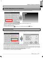
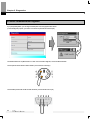
1
Right choice for ultimate yield
LSIS strives to maximize customers' profit in gratitude of choosing us for your
partner.
Programmable Logic Controller
XGT PANEL
XGT PANEL Series
User’s Manual
XP30-BTE
XP30-BTA
XP30-TTA
XP50-TTA
XP70-TTA
XP80-TTA
XP90-TTA
z Read
this manual carefully before
installing, wiring, operating, servicing
or inspecting this equipment.
z Keep
this manual within easy reach
for quick reference.
http://eng.lsis.biz
Safety Precautions
Before using the product…
To use the product safely and effectively, please read this instruction manual thoroughly before use.
► Please keep to the safety precaution, for it is to prevent accidents and potential danger from occurring.
► Safety precaution is classified into ‘Warning’ and ‘Caution’ and their meanings are as follows.
Warning
Violating the instruction may result in serious personal injury or death.
Caution
Violating the instruction may result in slight personal injury or product damage.
► The indicated illustrations on the product and in the manual have the following meanings.
Be cautious, for danger may be present.
Be cautious, for there is a possibility of an electric shock.
► After reading the instruction manual, keep it handy for quick reference.
1
Safety Precautions
Design Precautions
Warning
Install a safety circuit external to the HMI to protect the whole control system in case of
external power supply trouble.
Serious trouble may occur to the entire system due to erroneous output/operation of the HMI.
Design Precautions
Caution
In/output signal or communication cable should be at least 100mm apart from
High-voltage/power wires.
Otherwise, it may cause erroneous output/operation.
Installation Precautions
Caution
Use the HMI in an environment that meets the general specification contained in this
manual or datasheet.
Otherwise, it could result in electric shock, fire, erroneous operation or deterioration.
In case of much vibration in the installed environment, be sure to insulate the HMI from
direct vibration.
Otherwise, it could result in electric shock, fire or erroneous operation.
Be sure not to let foreign substances such as conductive debris inside the product.
Otherwise, it could result in electric shock, fire or erroneous operation.
2
Safety Precautions
Wiring Precautions
Warning
Be sure to turn off the HMI and external power before wiring.
Otherwise, it may result in an electric shock or damage to the product.
Caution
Wire correctly by checking each of the product’s rated voltage and terminal layout.
Otherwise, it may result in fire, electric shock or erroneous operation.
Tighten terminal screws with specified torque when wiring.
If terminal screws are loose, it may result in short circuits, fire or erroneous operation.
Use the exclusive HMI 3-type grounding for the FG terminal.
If not grounded, it may result in erroneous operation.
Be sure not to let any foreign substances such as wiring debris inside the module.
Such debris may cause fire, damage or erroneous operation.
3
Safety Precautions
Startup and Maintenance Precautions
Warning
Do not touch the terminals while power is on.
Otherwise, it may cause electric shock or erroneous operation.
Turn off the PLC and external power when cleaning or tightening the terminal.
Otherwise, it may cause electric shock or erroneous operation.
Do not charge, disassemble, heat, short circuit, solder, etc. the battery.
Mishandling the battery may cause overheating, crack, fire and may result in injury or fire.
Caution
Do not disassemble PCB from the product case or modify the product.
Otherwise, it may result in fire, electric shock or erroneous operation.
Use cellular phone or walky-talky at least 30cm away from the PLC.
Otherwise, it may result in erroneous operation.
Disposal Precaution
Caution
When disposing of this product or battery, treat it as industrial waste.
Otherwise, it may cause poisonous pollution or explosion.
4
Revision History
Revision History
Version
Date
Contents
V1.0
‘07.4
First Edition
V2.0
’09.10
1. Initial screen changed (horizontal bar -> square box type)
2. Menu name of initial screen changed
(Download From USB -> Storage Download)
3. Selecting one project file among many project files is available
4. Sending project file by CF card is available
5. File backup function by external storage equipment added
6. Format of backup file is changed into CSV format
7. New module XP80-TTA/AC added
8. Project upload function by external storage equipment added
9. Update function by external storage equipment added
10. XP30-BTE interface added
11. Figure and name of each part for XP30-BTE added
12. Specification of XP30-BTE added
13. Aux diagnosis function added
14. Dimension of XP30-BTE added
15. Specification of XP90-TTA/AC, XP70/80-TTA/DC added
16. Dimension of XP90-TTA/AC, XP70/80-TTA/DC added
17. PLC communication setting option in device menu added
18. Multi-Touch function in environment setting added
※ The number of User’s manual is indicated the right side of the back cover.
ⓒ LS Industrial Systems Co., Ltd 2006
All Rights Reserved.
Revised location
CH4, CH5, CH6, CH8
CH7.1
CH7
CH7
CH9
CH9
CH3, CH12, APP2
CH7
CH7
CH1
CH2
CH3
CH5
APP2
CH3, CH10
APP2
CH6.7
CH4.1
Chapter. 1 General Introduction ...................................................................................... 1-1~1-6
1.1 Usage of User Manual......................................................................................................................................................1-1
1.2 Feature...............................................................................................................................................................................1-2
1.3 Terminology .......................................................................................................................................................................1-6
Chapter. 2 System Configuration....................................................................................... 2-1~2-6
2.1 Name and Function of Each Part ....................................................................................................................................2-1
2.2 System Configuration .......................................................................................................................................................2-5
Chapter. 3 Standard Specification....................................................................................3-1~3-6
3.1 General Standards............................................................................................................................................................3-1
3.2 Function Standards...........................................................................................................................................................3-2
Chapter. 4 System Configuration.....................................................................................4-1~4-6
4.1 Touch Calibration...............................................................................................................................................................4-1
4.2 Backlight Setting................................................................................................................................................................4-2
4.3 Date Time Setting..............................................................................................................................................................4-3
4.4 PC Connection Setting .....................................................................................................................................................4-3
4.5 Ethernet Setting.................................................................................................................................................................4-4
4.6 Contrast Setting (only for XP30-BTA/DC).......................................................................................................................4-5
4.7 Environment Setting..........................................................................................................................................................4-5
Chapter. 5 Diagnostics.......................................................................................................5-1~5-5
5.1 Screen Diagnosis..............................................................................................................................................................5-1
5.2 Touch Diagnosis................................................................................................................................................................5-2
5.3 Backup Memory Diagnosis..............................................................................................................................................5-2
5.4 Flash Memory Diagnosis Function..................................................................................................................................5-3
5.5 CF Card Diagnosis............................................................................................................................................................5-3
5.6 Serial Communication Diagnosis ....................................................................................................................................5-4
5.7 LED Diagnosis...................................................................................................................................................................5-5
5.8 Aux Diagnosis....................................................................................................................................................................5-5
Chapter. 6 Viewing Information of PLC Connection Status .......................................6-1~6-5
6.1 Connection Information ....................................................................................................................................................6-2
6.2 PLC Information ................................................................................................................................................................6-2
6.3 History of PLC Error ........................................................................................................................................................6-3
8
6.4 History of PLC Mode Conversion ..................................................................................................................................6-3
6.5 History of PLC Power .....................................................................................................................................................6-4
6.6 History of PLC System ...................................................................................................................................................6-4
6.7 PLC Communication Configuration Settings ................................................................................................................6-5
Chapter. 7 Storage Function .................................................................................................... 7-3
7.1 General Introduction ........................................................................................................................................................7-1
7.2 Downloading Project through the Storage Equipment ..................................................................................................7-2
7.3 Uploading Project through the Storage Equipment .......................................................................................................7-2
7.4 Updating the Device through Storage Equipment .........................................................................................................7-3
Chapter. 8 XGT Panel S/W Update .......................................................................................... 8-1
8.1 General Introduction ........................................................................................................................................................8-1
Chapter. 9 File Backup through External Storage Equipment........................................... 9-5
9.1 Path Structure in case of File Backup .............................................................................................................................9-1
9.2 Operation setting when there is no Space for Backup...................................................................................................9-3
9.3 Monitoring Connection Status of External Storage Equipment.....................................................................................9-4
Chapter. 10 Installation and Wiring............................................................................. 10-1~10-8
10.1 Installation......................................................................................................................................................................10-1
10.1.1 Installation environment.....................................................................................................................................10-1
10.1.2 Notice in handling...............................................................................................................................................10-2
10.1.3 Notice in installing the panel..............................................................................................................................10-2
10.2 Wiring .............................................................................................................................................................................10-5
10.2.1 Power wiring.......................................................................................................................................................10-5
10.2.2 Ground wiring .....................................................................................................................................................10-8
Chapter. 11 Maintenance ...............................................................................................11-1~11-3
11.1 Maintenance..................................................................................................................................................................11-1
11.2 Daily Maintenance.........................................................................................................................................................11-1
11.3 Periodical Maintenance ................................................................................................................................................11-2
Chapter. 12 EMC Standard Certification ................................................................... 12-1~12-2
12.1 Requirement for EMC Standard Certification ...........................................................................................................12-1
12.1.1 CE standard certification ..................................................................................................................................12-1
12.1.2 MIC standard certification ................................................................................................................................12-2
9
12.2 Requirement for Low Voltage Command Suitability..................................................................................................12-2
12.2.1 Standard applied for XGT Panel.......................................................................................................................12-2
12.2.2 Selection of XGT Panel ...................................................................................................................................12-2
Appendix 1. Troubleshooting ......................................................Appendix1-1~Appendix1-18
1. Type of Problem .................................................................................................................................................Appendix 1-1
2. Problem when Starting.......................................................................................................................................Appendix 1-1
3. Reaction Problem when touching.....................................................................................................................Appendix 1-2
4. Indication Problem of Figure and Object..........................................................................................................Appendix 1-2
5. Communication Problem...................................................................................................................................Appendix 1-5
6. CF/USB Removal of Memory Card..................................................................................................................Appendix 1-6
7. Error Message during Execution of Program ..................................................................................................Appendix 1-7
Appendix 2. Dimension ............................................................... Appendix 2-1~ Appendix 2-3
10
Chapter 1. General Introduction
Chapter 1. General Introduction
1.1 Usage of User Manual
This manual provides information of each product’s specification, usage and so on. This is necessary to use XGT Panel for medium and large
HMI system.
The user manual’s configuration is as follows.
Sequence
Category
Contents
Chapter 1
General Introduction
It describes this manual’s configuration, product’s feature and term.
Chapter 2
System Configuration
It describes feature and system configuration of each XGT Panel.
Chapter 3
Standard Specification
It describes XGT Panel’s general and function specification.
Chapter 4
System Configuration
It describes XGT Panel’s system configuration.
Chapter 5
Diagnostics
It describes XGT Panel’s self-diagnosis.
Viewing information of
PLC Connection Status
Transmission of Project
from USB Storage Device
It describes the way on connection status information of PLC which is
connected with XGT Panel.
Chapter 8
XGT Panel S/W Update
It describes the way to update engine at XGT Panel.
Chapter 9
Backup files by using
Storage Devices
It describes the way to backup recipe, logging and etc. files by using
storage devices.
Chapter 10
Installation and Wiring
It describes an installation, wiring and caution for reliability of PLC system.
Chapter 11
Maintenance
It describes inspection category and method for long normal operation of PLC
system.
Chapter 12
EMC Standard
It describes system configuration for EMC standard.
Appendix 1
Troubleshooting
It describes a variety of error contents and measure.
Appendix 2
Dimension
It describes the dimension of XGT Panel.
Appendix 3
Warranty and
Environment Policy
Chapter 6
Chapter 7
It describes the way to execute the project by using USB storage device.
-
Remark
This manual doesn’t describe connection with XP-Builder and PLC. For their own function, Please refer to the related
manuals.
1-1
Chapter 1. General Introduction
1.2 Feature
XGT Panel has the following features.
(1) Diverse external interface
(a) It maximizes custom’s use by providing diverse external interface including USB, CF card and Ethernet.
Expansion connector
CF card
Communication
Module
Memory Interface
Logging data
Image/font data
USB host
Printer
Etc.
Tool port (RS-232C): XP-Builder
USB Storage
Device
Keyboard,
Mouse
(b) It can be connected with control device such as PLC, INVERTER.
• It can be connected by RS-232C, RS-422/485, Ethernet (10/100 BASE-T).
Ethernet
XP-Builder
• Inverter
Open network
1-2
• Inverter
Chapter 1. General Introduction
(c) XP30-BTE, economic type, is not supported for Ethernet, expansion connector and CF card..
Battery Cover
RS232C
RS422/RS485
Terminal Block Type
USB Port
(2) Based on Windows CE
(a) Adoption of Microsoft Company’s Windows CE
• Windows CE 5.0
(b) Advantage
• It provides stable software capacity by using Microsoft Company’s platform.
• It can process diverse function simultaneously.
• It provides diverse interface including Ethernet, USB, CF card.
• The user interface including mouse and keyboard can be connected.
• It has high flexibility like computer software.
• Fast reaction is available when adding new equipment.
• Wide data sharing and management with upper system is available. (Later)
(3) Improvement of project transmission time
(a) It provides Ethernet which is faster than RS-232C.
Download
Upload
(b) It provides the transmission function from USB storage device.
Data change
1-3
Chapter 1. General Introduction
(4) High quality screen
(a) It provides the high quality screen and clearness by high quality LCD.
• It adopts TFT LCD which supports the 65,536 colors. (XP30-BTE/DC and XP30-BTA/DC adopts STN Mono LCD.)
(b) It provides diverse graphic type.
• It is available to express precisely and actually.
• It provides the simple moving function with GIF support.
(5) Analog touch Panel
(a) It adopts analog (resistor film method) Touch Panel.
• Visibility is improved without the grids.
(b) It provides high touch resolution.
• It can control Touch Panel precisely.
(6) Multilingual and diverse font
(a) It supports the multilingual function.
• It transmits the Windows/User font used in computer to XGT Panel.
• Additional language development is not necessary.
• Multilingual language is an advantage of Windows CE.
(b) It can express four kinds of language simultaneously.
• It can express 4 kinds of language simultaneously.
• Language switching is available by using special switch during operation.
(c) It can provide the various fonts.
• Various expressions are available by using the Windows/User font.
• Font size and type can be adjusted freely.
1-4
Chapter 1. General Introduction
(7) Advanced function
(a) Alarm function
• The History alarm can be classified alarm group and alarm list and selected alarm can be expressed by alarm search.
• The Flow alarm indicates current or the latest alarm at the bottom of screen.
• The System alarm indicates the important problems from operation.
(b) Logging function
• It provides conditional logging according to device condition and continuous periodic logging which operates periodically
according to time and device status.
• It provides 255Kbyte areas for backup.
• Backup into CF card or USB storage device is available.
• Backup data’s type is stored in Excel, it is easy to use.
(c) Recipe function
• It provides READ/WRITE function.
• A recipe provides Max. 100 Dwords and 16 blocks.
• Backup into the CF card or USB storage device is available.
• Backup data’s type is stored in Excel, it is easy to use.
(d) Scheduler function
• It can be set up to Max. 32.
(e) Print function
• It provides a Screen/Alarm print function.
• It can be printed by USB printer.
(f) Script function
• It provides more flexible function by user Script.
• It can be diversely applied to such as including Global/Object/Screen indication and so on.
(8) Stable product suitable for international standards
(a) CE, KCC standard acquisition
(b) UL standard acquisition
1-5
Chapter 1. General Introduction
1.3 Terminology
It describes terms used in this manual.
Term
1-6
Definition
Example
Module
A standard element that has a specified function which configures the system.
Devices such as I/O board, which inserted onto the mother board or base unit.
Ex.) CPU module
Power module,
I/O module
Unit
A single module or group of modules that perform an independent
operation as a part of PLC system.
Ex.) Basic unit,
Extension unit
PLC system
System consisted of PLC and peripheral device which can be controlled by
user program.
-
XP-Builder
Software used to write and edit the project.
-
Cnet module
Computer Link
-
FEnet module
Fast Ethernet Network
-
RTC
Abbreviation of ‘Real Time Clock’. It is used to call general IC that contains
clock function.
-
Chapter 2. System Configuration
Chapter 2. System Configuration
Here describes the feature of XGT Panel and system configuration.
2.1 Name and Function of Each Part
1. XP30-BTA, XP30/50/70/80-TTA
Number
①
Name
Front view
Description
1) Analog touch panel: User touch input
2) LCD: screen indication
Indicates operation status of device
②
LED Status
Green
Red
Normal RUN status
(monitoring, downloading the project data)
Initializing the status when booting
(HMI does not operate)
Error occurs
(communication error, project data error)
2-1
Chapter 2. System Configuration
Number
Name
Description
③
Panel fixed part
XGT Panel is fixed at panel by bracket.
④
CF card interface
1) Logging/recipe/screen data backup
2) Upgrade of windows CE is available.
⑤
Power connection
terminal
It consists of power input and FG terminal.
⑥
USB interface
It consists of 2 ports.
1) USB memory connection: logging/recipe/screen data backup
2) USB memory connection: project data transmission/backup
3) User interface connection: use of mouse/keyboard
4) Printer connection: printing is available
⑦
Extension port
Extension module installation
⑧
Reset switch
Hardware reset switch
TOOL interface
RS-232C interface
1) project data transmission
2) logging/recipe/alarm/screen data backup
3) machine software upgrade
⑨
Setting switch
Device setting switch
No.1
No use
A setting
Normal operation (basic setting)
B setting
When upgrading Windows CE
A setting
Use of Watchdog (basic setting)
B setting
No use of Watchdog
A setting
RS-422/485 terminal resistor setting (120Ω)
B setting
No use of RS-422/485 terminal resistor
No.2
⑩
No.3
No.4
⑪
Extension module
fixation hall
Extension module fixation hall
⑫
RS-422/485 connector
RS-422/485: PLC/control machine communication
⑬
RS-232C connector
RS-232C: PLC/control machine communication
⑭
Ethernet terminal
Ethernet: 10/100 BASE-T
1) Project data transmission
2) logging/recipe/alarm/screen data backup
3) machine software upgrade
4) PLC/control machine communication
⑮
FG terminal
FG terminal hole for extension module
Remark
(1) For details about communication connection, please refer to the communication user manual.
(2) For details about installation, please refer to the Chapter 10
2-2
Chapter 2. System Configuration
When you use the XGT Panel, the prevention tape is installed to prevent battery discharge.
If you remove this prevention tape, backup is available.
In order to remove tape, pull tape downward like the following figure.
Prevention
tape
2. XP30-BTE
2-3
Chapter 2. System Configuration
Number
①
Name
Front view
Description
1) Analog touch panel: User touch input
2) LCD: screen display
Indicates operation status of module.
②
LED Status
Green
Red
Normal RUN status
(monitoring, downloading the project data)
Initializing mode when booting
(HMI does not Ready)
Error occurs
(communication error, project data error)
③
Panel fixed part
XGT Panel is fixed at panel by bracket.
④
Power terminal
cover
Prevention from electric shock
⑤
USB interface
⑥
Communication
interface
1) USB memory connection: logging/recipe/screen data backup
2) USB memory connection: project data transmission/backup
3) User interface connection: use of mouse/keyboard
4) Printer connection: printing is available
RS-232C, RS-422/485: For communication with controller
(PLC)
⑦
Reset switch
Hardware reset switch
⑧
Battery cover
Open or close when replacing the battery
Tool interface
RS-232C interface
1) Project data transmission
2) Logging/recipe/alarm/screen data backup
3) Machine software upgrade
⑨
Setting switch
Module setting switch
No.1
Reserved
A setting
Normal operation (basic setting)
B setting
When upgrading Windows CE
Asetting
Use of Watchdog (basic setting)
B setting
No use of Watchdog
A setting
RS-422/485 terminal resistor setting (120Ω)
B setting
No use of RS-422/485 terminal resistor
No.2
⑩
No.3
No.4
⑪
2-4
Power terminal
It consists of power input and FG terminal
Chapter 2. System Configuration
2.2 System Configuration
In order to use XGT Panel, write project data at the XP-Builder and transmit it to the XGT Panel.
XGT Panel can be basically connected through RS-232C.
Maximum communication speed is 115,200 [bps].
RS-232C communication speed is not fast so it takes long time to transmit project data into XGT Panel.
Project data can be quickly transmitted through Ethernet.
When LAN system is configured like the following figure, you can use it easily and effectively.
LAN
In case that LAN system is not configured, it provides 1:1 connection. (LAN cable should be cross cable.)
Ethernet
2-5
Chapter 2. System Configuration
When communication is not available to transmit project data, USB storage device is available
For details, please refer to the Chapter.7 and XP-Builder user manual.
Remark
1) We recommend Ethernet more than RS-232C.
2) For the Ethernet cable manufacture, please refer to the communication manual.
3) For the project transmission method, please refer to the XP-Builder manual.
4) Ethernet is not supported on XP30-BTE
2-6
Chapter 3. Standard Specification
Chapter 3. Standard Specification
3.1 General Standards
XGT Panel’s general standard is as follows.
No.
Category
Standard
Related standard
1
Ambient
operating
temperature
0℃∼+50℃
2
Storage
temperature
-20℃∼+60℃
3
Operating
humidity
10∼85%RH, non-condensing.
4
Storage
humidity
10∼85%RH, non-condensing.
Occasional vibration
5
Vibration
resistance
count
Frequency
Acceleration
Amplitude
5 ≤ f < 9㎐
-
3.5 mm
9 ≤ f ≤ 150㎐
9.8㎨
-
10 times for each
Continuous vibration
6
7
Shock
endurance
Noise Immunity
X, Y, Z axis
Frequency
Acceleration
Amplitude
5 ≤ f < 9㎐
-
1.75 mm
9 ≤ f ≤ 150㎐
4.9㎨
-
IEC 61131-2
* Maximum shock acceleration: 147㎨ (15g)
IEC 61131-2
* Duration time: 11㎳
* Pulse wave: half sine pulse (3 shocks per axis, on X, Y, Z axis)
LSIS’
Square wave
Impulse noise
AC: ±1,500V
DC: ±1,000V
Electrostatic
discharge Immunity
Voltage: 6 kV (Discharge by contact)
IEC 61131-2
IEC 61000-4-2
Radiated
electromagnetic
field noise
27 ~ 500 MHz, 10 V/m
IEC 61131-2
IEC 61000-4-3
Fast transient &
Burst noise
Category
Power module
Voltage
2 kV
Standard
Communication interface IEC 61131-2
8
Atmosphere
Free from corrosive gases and excessive dust
9
Altitude
Less than 2,000m (6,562 ft)
10
Pollution degree
Less than 2
11
Cooling method
Air-cooling
1 kV
IEC 61000-4-4
3-1
Chapter 3. Standard Specification
Remark
(1) IEC(International Electrotechnical Commission)
: International private group facilitating international cooperation of electric/electronic standardization, issuing international
standards and operating the compliance evaluation systems.
(2) Pollution degree
: As an index representing the pollution degree of an environment to determine the insulation of a device, pollution degree 2
generally means the status generating non-conductive contamination. However, it also contains the status generating
temporarily conduction due to condensation.
(3) Radiated electromagnetic field noise for XP30-BTE is 80 ~ 1000MHz, 10 V/m (All others are same as shown on the table)
3.2 Function Standards
XGT Panel’s function standard is as follows.
1. DC type
(1) Medium Series
Item
Display type
XP30-TTA/DC
STN mono LCD
TFT Color LCD
Screen size
14 ㎝ (5.7”)
Display Resolution
320 x 240 pixel
Color indication
8 step Gray Scale
65,000 Color
Indication degree
Left/Right: 45 deg.
Upper: 40 deg.
Lower: 20 deg
Backlight
LED Type CCFL (concluding LCD)
Left/Right: 70 deg.
Upper: 50 deg.
Lower: 70 deg.
CCFL (concluding LCD),
Supporting automatic On/Off
Backlight duration
50,000 hr.
60,000 시간
Contrast
Adjust through touch/parameter
-
Brightness
230cd/㎡
400cd/㎡
Touch panel
4 – Line type, analog
Sound Output
Magnetic buzzer
Process
ARM920T (32bit RISC), 200MHz
Graphic accelerator
Hardware Accelerator
Memory
3-2
Medium series
XP30-BTA/DC
XP30-BTE/DC
Flash
Operating RAM
Backup RAM
16MB
32MB
128KB
32MB
64MB
512KB
Backup data
Date/Hour data and Logging/Alarm/Recipe data
Battery duration
Approx. 3 years (Operating ambient temperature of 25℃)
Ethernet
-
USB Host
1 Channel
RS-232C
Terminal Block
1 Channel, IEEE802.3, 10/100Base-TX
2 Channels, USB 2.0
(printer, USB memory stick driver is available)
2 Channels
Chapter 3. Standard Specification
Item
RS-422/485
CF Card
Expansion module
XP30-BTE/DC
Terminal Block
-
Medium series
XP30-BTA/DC
XP30-TTA/DC
1 Channel,RS-422/485 mode
1 Slot (Compact Flash)
Option module is available
Multi-language
Up to 4 language simultaneously
Animation
GIF format is available
Recipe
available
Data logging
available
Script executor
available
Certifications
CE, UL, KCC
Protection standard
IP65F
Dimension (mm)
Panel cut (mm)
181 x 140 x 56.5
156 x 123.5
Rated voltage
181 x 140 x 66.5
156 x 123.5
DC24V (Actual Range: 19.2 ~ 28.8V)
Power consumption (W)
5
8.5
Weight(Kg)
0.62
0.75
(2) Large Series
Item
Large Series
XP70-TTA/DC
XP50-TTA/DC
Display type
Screen size
TFT Color LCD
21 ㎝(8.4”)
Display Resolution
26 ㎝(10.4”)
31㎝(12.1”)
640 x 480 pixel
Color indication
Indication degree
XP80-TTA/DC
800 x 600 pixel
65,000 Color
Left/Right: 65 deg.
Upper: 50 deg.
Lower: 60 deg.
Left/Right: 65 deg.
Upper: 45 deg.
Lower: 65 deg.
Left/Right: 65 deg.
Upper: 45 deg.
Lower: 75 deg.
Backlight
CCFL (Replacement is available), Supporting automatic On/Off
Backlight duration
50,000 hr.
Brightness
480cd/㎡
430cd/㎡
8 Line, analog
Sound Output
Magnetic buzzer
Process
ARM920T (32bit RISC), 200MHz
Graphic accelerator
Hardware Accelerator
Memory
Touch panel
Flash
Operating RAM
Backup RAM
400cd/㎡
32MB
64MB
512KB
Backup data
Date/Hour data and Logging/Alarm/Recipe data
Battery duration
Approx. 3 years (Operating ambient temperature of 25℃)
Ethernet
1 Channel, IEEE802.3, 10/100Base-TX
3-3
Chapter 3. Standard Specification
Item
XP50-TTA/DC
Large Series
XP70-TTA/DC
XP80-TTA/DC
USB Host
2 Channels, USB 2.0 (printer, USB memory stick driver is available)
RS-232C
2 Channels
RS-422/485
1 Channel, RS-422/485 mode
CF Card
1 Slot (Compact Flash)
Expansion module
Option module is available
Multi-language
Up to 4 language simultaneously
Animation
GIF format is available
Recipe
available
Data logging
available
Script executor
available
Certifications
CE, UL, KCC
Protection standard
Dimension (mm)
Panel cut (mm)
IP65F
240 x 174 x 73
228.5 x 158.5
Rated voltage
317 x 243 x 73
294.5 x 227.5
DC24V (Actual Range: 19.2 ~ 28.8V)
Power consumption (W)
20
27
30
Weight(Kg)
1.4
2.2
2.4
Remark
(1) Notice in connecting with power
: Connecting AC power to the device using DC power may cause product break or fire. Be careful when connecting
(2) FG connection
: Use ⑤FG terminal (Chapter 2.1) for FG of the device. ⑮FG (Chapter 2.1) is for FG terminal of extension card.
(Except XP30-BTE)
(3) Prevention tape of Battery discharge
: There is prevention tape is to prevent the battery discharge. In order to use backup, remove the prevention tape.
(4) Battery operation and duration
: Battery is used to reserve backup data and RTC (data/time) when power is off.
Because battery is used when power is off, battery is not consumed when power is on.
(5) LCD Backlight replacement
: In XP50-TTA/DC, XP70-TTA/DC, XP80-TTA/DC, LCD backlight is replaceable.
However in XP30-BTE/DC, XP30-BTA/DC and XP30-TTA/DC, LCD backlight is not replaceable because
LCD and backlight is all-in-one type.
3-4
Chapter 3. Standard Specification
AC Type
Item
Large Series
XP80-TTA/AC
XP70-TTA/AC
Display type
XP90-TTA/AC
TFT Color LCD
Screen size
26cm (10.4”)
31cm (12.1”)
38cm (15”)
Display Resolution
640 x 480 pixel
800 x 600 pixel
1024 x 768 pixel
Color indication
Indication degree
Backlight
Backlight Duration
Contrast
Brightness
65,000 Color
Left/Right: 65 deg.
Left/Right: 65 deg.
Left/Right: 75 deg
Upper : 45 deg.
Upper : 45 deg.
Upper : 50 deg
Lower : 65 deg.
Lower : 75 deg.
Lower : 60 deg
CCFL (Replacement is available), Supporting automatic On/Off
50,000 hr.
430cd/㎡
400cd/㎡
450cd/㎡
Touch Panel
8 Line, analog
Sound Output
Magnetic buzzer
Process
ARM920T (32bit RISC), 200MHz
Graphic Accelerator
Flash
Operating Ram
Backup Ram
Hardware Accelerator
32MB
64MB
Memory
2.
64MB
128MB
512KB
Backup data
Date/Hour data and Logging/Alarm/Recipe data
Battery duration
Approx. 3 years (Operating ambient temperature of 25℃)
Ethernet
1Channel, IEEE802.3, 10/100Base-TX
USB Host
RS-232C
RS-422/485
CF Card
Expansion Module
Multi-language
Animation
Recipe
Data logging
2 Channels, USB 2.0 (printer, USB memory stick driver is available)
2 Channels
1 Channel,RS-422/485 mode
1 Slot (Compact Flash)
Option module is available
Up to 4 language simultaneously
GIF format is available
available
available
Script executor
available
Certification
Protection standard
Dimension (mm)
Panel cut (mm)
Rated voltage
Power consumption (W)
Weight (Kg)
CE, UL, KCC
IP65F
317 x 243 x 73
294.5 x 227.5
37
2.2
395 x 294 x 73
383.5 x 282.5
AC100~240V
40
2.4
46
3.9
3-5
Chapter 3. Standard Specification
Remark
(1) Notice in connecting with power
: If you connect DC power to the device using AC power, the product doesn’t work. Please be careful when connecting.
(2) FG connection
: Use ⑤FG terminal (Chapter 2.1) for FG of the device. ⑮FG (Chapter 2.1) is for FG terminal of extension card.
(Except XP30-BTE)
(3) Prevention tape of Battery discharge
: There is prevention tape is to prevent the battery discharge. In order to use backup, remove the prevention tape.
(4) Battery operation and duration
: Battery is used to reserve backup data and RTC (data/time) when power is off.
Because battery is used when power is off, battery is not consumed when power is on.
(5) LCD Backlight replacement
: In XP70-TTA/AC, XP80-TTA/AC, XP90-TTA/AC, LCD backlight is replaceable.
3-6
Chapter 4. System Configuration
Chapter 4. System Configuration
It describes the system configuration including XGT Panel’s time setting, Ethernet connection setting, connection with
PC and backlight.
If you press [Settings] button in XGT Panel’s basic screen, you can set XGT Panel’s environment as follows.
XGT Panel’s basic screen
XGT Panel’s System Configuration screen
4.1 Touch Calibration
When the location is not recognized in XGT Panel, Touch’s scale can be adjusted in XGT Panel. If you press [Touch Calibration] button in
System Configuration, the setting screen shows up. If you press five ‘+’ marks, XGT Panel’s touch location adjustment is completed.
4-1
Chapter 4. System Configuration
If you press two points simultaneously while [Allow Multi-touch] is selected, XGT Panel recognizes as if middle point between two points is
selected. If you press two points simultaneously while [Allow Multi-touch] is not selected, XGT Panel recognizes as if any point is not
selected.
Remark
(1) XGT Panel’s Touch Calibration setting is basically set. If Touch location error is big, adjusting menu with touch can be
hard through touch. In that case, You can select the Touch Calibration setting menu by USB mouse.
(2) When touch location changes in using, redo touch setting.
(3) If you don’t allow Multi-touch, sensitivity is lower than when allowing Multi-touch.
4.2 Backlight Setting
If you press [Backlight Setting] button in [System Configuration] screen as follows, setting screen shows up.
Against no use for long time through XGT Panel, you can set ‘Automatically turn off backlight’ function.
Set whether you use backlight automation On/Off function or not and time, then press OK button as follows.
As above, if you input 30, the backlight automatically turns off after 30 minute later. In off status, if you touch the panel, the backlight turns on.
4-2
Chapter 4. System Configuration
4.3 Date Time Setting
If you press [DateTime Setting] button in [System Configuration] as follows, you can set XGT Panel’s data and time.
Remark
You can set data/time at device information of communication dialog at the XP-Builder.
For details, please refer to the XP-Builder’s manual.
4.4 PC Connection Setting
If you press [PC Conn Setting] button in [System Configuration] screen as follows, you can set RS-232C and TCP/IP’s port number to
communicate with PC.
Remark
The condition is set as the above. No other setting is required. But in case of changing RS-232C’s communication speed, change
as above.
4-3
Chapter 4. System Configuration
4.5 Ethernet Setting
If you press [Ethernet Setting] button in [System Configuration] screen as follows, you can change IP to use Ethernet.
You can change IP address by pressing [Set] button of each IP address, Subnet Mask and Gateway. By pressing OK button, changed IP
information is reserved.
Remark
We recommend the following method, when connecting with PC solely.
1) XGT Panel setting
- IP Address : 192.168.0.10
- Subnet Mask: 255.255.255.0
- Gateway
: 192.168.0.1
2) PC setting
- IP Address : 192.168.0.11
- Subnet Mask: 255.255.255.0
- Gateway
: 192.168.0.1
Ethernet is not supported on XP30-BTE
If you reboot after pressing [Disable] button, the device will not use Ethernet. In this case, booting speed gets faster. If you use
Ethernet again, reboot after pressing [Enable].
[
4-4
Chapter 4. System Configuration
4.6 Contrast Setting (only for XP30-BTA(BTE)/DC)
If you press [Contrast Setting] button on [System Configuration] screen, you can adjust mono LCD’s Contrast.
UP button increase Contrast, DOWN button decrease Contrast. Contrast value is between 0~100.
Adjustment is only available for mono type XP30-BTA.(BTE)
Adjustment is available during operation.
If you press the screen for 3 second,
shows up. You can adjust contrast by pressing
button.
4.7 Environment Setting
If you press [Environment Setting] button in [System Configuration] screen as follows, you can set ‘Auto Goto Screen’ and ‘Buzzer On/Off’.
When setting [Auto Goto Screen], XGT Panel is rebooted. Or when downloading the edit data is completed, the screen automatically shows
up. If you cancel this setting, the user should press ‘Start’ button in order to move to the screen.
If you select [Quick Start], when starting screen, screen shows promptly without showing progress bar because it doesn’t caching the image
in advance. However, if you select this option, first screen shows slowly. Especially, if there are many animation object in screen, it may takes
several seconds based on image. But fast screen switching is available since second screen switching.
If you select [Hide Mouse Cursor], mouse cursor doesn’t show after screen switching
You can set whether you use buzzer through [Buzzer On/Off] button.
4-5
Chapter 4. System Configuration
If you setting [Disable menu Bar], the menu bar basically provided to go out from monitoring screen to the waiting screen doesn’t show. In
this case, if you want to go out to the waiting screen, you have to use the special switch to close the monitoring screen.
If you select the image through [Set Background Image], background image of waiting screen is set as the selected image. If you want to
cancel, press [Delete Background Image]
Remark
The buzzer can be set at the machine information tap of communication conversation box.
Please refer to the XP-Builder’s manual.
4-6
Chapter 5. Diagnostics
Chapter 5. Diagnostics
It describes the diagnosis function for XGT Panel’s communication terminal, screen and touch function.
If you press [Diagnostics] button on the XGT Panel’s basic screen, the menu for diagnosis shows up.
XGT Panel’s environment setting screen
XGT Panel’s basic screen
5.1 Screen Diagnosis
If you press [Screen] button, screens continuously change into diverse color with buzzer. For XP30-BTA/DC product, screen changes into 8
steps’ light. After all screen for diagnosis pass. Then, Close button shows up with white ground.
If you press Close button, the initial screen shows up.
Screen when XGT Panel’s screen diagnosis
XGT Panel’s XGT Panel diagnosis screen
Item
Display
XP30-BTE/DC
XP30-BTA/DC
BLACK > 8 steps gray scale
screen > WHITE
XP30-TTA/DC
XP50-TTA/DC
XP70-TTA/AC(DC)
XP80-TTA/AC(DC)
XP90-TTA/AC
RED > GREEN > BLUE > BLACK > WHITE
5-1
Chapter 5. Diagnostics
5.2 Touch Diagnosis
If you touch the screen, the touched location is displayed as follows. If pressing the [OK] button, you can quit the screen.
If the touched location is not correct, reset the Touch setting. For detailed information, please refer to the Chapter 4. System Configuration.
5.3 Backup Memory Diagnosis
If you press [Backup Memory] button, you can see the result of diagnosis in the result windows.
Remark
(1) If ‘NVRAM Data Access … Fail’ error is occurred, please contact with customer service center.
(2) If ‘BATTERY STATUS … BAD’ error is occurred, battery should be changed. Please contact with Customer service
center.
5-2
Chapter 5. Diagnostics
5.4 Flash Memory Diagnosis Function
If you press [NOR Flash] button, you can see the result of diagnosis in the result widows.
Remark
If ‘Read Disk Information Error!’ occurs, please contact with Customer service center.
5.5 CF Card Diagnosis
If you press [CF Card] button, the result of diagnosis shows up in the result windows.
Remark
If ‘Read Disk Information Error!’ occurs, please contact with Customer service center.
CF Card is not supported on XP30-BTE.
5-3
Chapter 5. Diagnostics
5.6 Serial Communication Diagnosis
If you press [Serial] button, you can diagnose Serial ports which is equipped at XGT Panel.
(In case of diagnosis purpose, you have to connect the loop-back terminal at each port.)
The followed feature is Loop Back terminal. In case of communication diagnosis, connect as followed feature.
The tool port terminal should be made as follows. (Connect the No.2 and 6 pin)
The RS-232C port terminal should be made as follows. (Connect the No.2 and 3 pin)
5-4
Chapter 5. Diagnostics
The RS-422/485 port terminal should be made as follows. (Connect the Pin No.4 with 8 and Pin No. 5 with 9)
5.7 LED Diagnosis
If you press [LED] button, you can check whether LED is converted into designated color or not at the bottom of XGT Panel.
5.8 AUX Diagnosis
If you press [Aux Interface] button, you can check the functions of card that is currently connected.
(Not supported on XP30-BTE)
5-5
Ch.6 Viewing Information of PLC Connection Status
Chapter 6. Viewing Information of PLC Connection Status
You can see the diverse information including XGT Panel’s and PLC’s CPU information through View PLC Connection Status Information.
[Method]
(a) Select [PLC Information] in the menu.
(b) Select the designated PLC. The listed PLC is the same as connection number which is set at [Common - Project Property Setting –
PLC/Device settings] in XP-Builder.
(c) Press [SHOW INFO]
(d) You can check the connection information of XGT Panel, information of PLC CPU, history of error, mode conversion, PLC power cut
and system.
Remark
You can check the status of PLC connection after project data is transmitted into XGT Panel.
6-1
Ch.6 Viewing Information of PLC Connection Status
6.1 Connection Information
You can check the setting items for the connection with PLC such as Vender of PLC, Target device, Connection type, Connection
information and Timeout value in the XP-Builder.
6.2 PLC Information
You can check CPU type of PLC, operation mode, state, version, and scan time.
Remark
The following PLC is available for view of PLC information.
- MASTER-K CPU, FEnet, Cnet
- GLOFA-GM CPU, FEnet, Cnet
- XGK/XGB/XGI CPU, FEnet, Cnet
6-2
Ch.6 Viewing Information of PLC Connection Status
6.3 History of PLC Error
You can check the PLC Error History.
Remark
The following PLC is available for viewing Error History.
- MASTER-K CPU doesn’t have the Error History.
- GLOFA-GM CPU
- XGK/XGI CPU
- XGB CPU doesn’t have the Error History.
6.4 History of PLC Mode Conversion
You can check the history about our PLC’s RUN/STOP operation mode.
Remark
The following PLC is available for viewing PLC operation mode conversion history.
- MASTER-K CPU doesn’t have the history about operation mode conversion.
- GLOFA-GM CPU
- XGK/XGI CPU
- XGB CPU doesn’t have the history about operation mode conversion.
6-3
Ch.6 Viewing Information of PLC Connection Status
6.5 History of PLC Power
You can check the history about when PLC was turned on and off
Remark
The following PLC is available for viewing the history of when our PLC was turned off and on.
- MASTER-K CPU doesn’t have the history about when our PLC was turned on and off.
- GLOFA-GM CPU
- XGK/XGI CPU
- XGB CPU doesn’t have the history about when our PLC was turned on and off.
6.6 History of PLC System
You can check history about PLC system.
Remark
The following PLC is available for viewing history about system..
- MASTER-K CPU doesn’t have the history about system.
- Only GLOFA-GM CPU (GM4C) has the history about system. Other CPUs don’t have the history about system.
- XGK/XGI CPU
- XGB CPU doesn’t have the history about system.
6-4
Ch.6 Viewing Information of PLC Connection Status
6.7 PLC Communication Configuration Settings
You can select [Settings] button to change PLC communication settings
Remark
-
For further information about the settings, please refer to the PLC user manual.
[Program Monitor] button is activated in case of LSIS PLC Direct Driver
6-5
Chapter 7. Storage Function
Chapter 7. Storage Function
7.1 General Introduction
Downloading the user project made in XP-Builder from PC, uploading the project stored in the device to PC, updating the device and
etc are available through connection with XGT Panel with Serial cable or Ethernet cable generally. However, when those connections
are not available, you can use CF card, USB storage equipment
1. If you touch [Storage Function], the following dialog box shows.
2. In case of downloading the project by using CF card or USB storage equipment, touch [Project Download] button.
3. In case of transmitting the project data stored in the device to CF card or USB storage equipment, touch [Project Upload] button.
4. In case of updating the XGT Panel with XGT Panel Software stored in CF card or USB Storage equipment, touch [XGTPanel
Update]
7-1
Chapter.7 Storage Function
7.2 Downloading Project through the Storage Equipment
1. If you touch [Project Download], the following dialog shows.
2. In case of selecting [USB], the directory list under the path, \USB Storage\XP_Project\ shows. In case of selecting [CF], the
directory list under the path, \Storage Card\XP_Project\ shows. In case of downloading the project by using storage equipment,
the project should be saved in the one lower directory between those two directories.
3. Select one among directory lists and touch [OK]. Then downloading will start.
7.3 Uploading Project through the Storage Equipment
1. If you touch [Project Upload], the following dialog shows.
2. In case of selecting [USB], the path, \USB Storage\XP_Backup\, shows. In case of selecting [CF], the path, \Storage
Card\XP_Backup\, shows. Select one between two.
3. If you touch [OK] button, project backup file is transmitted to the selected path.
4. The project backup file is saved when Download project backup file is selected when downloading the project.
If you don’t select, project backup file is not saved in the device and transmission to the storage equipment is not available.
7-2
Chapter 7. Storage Function
7.4 Updating the Device through Storage Equipment
1. If you touch [Project Upload], the following dialog shows.
2. In case of selecting [USB], the directory list under the path, \USB Storage\XP_Project\ shows. In case of selecting [CF], the
directory list under the path, \Storage Card\XP_Project\ shows. In case of updating the device by using storage equipment, the
XGTPanel Softwareproject should be saved in the one lower directory between those two directories.
3. If you touch [OK] button, the device is updated with XGTPanel Software in the designated path.
Notice
(1) Do not remove USB storage equipment or turn off the device during operation. It may cause abnormal installation of
project data.
(2) Do not remove or move the directory except CF or USB storage equipment. It may cause abnormal operation.
7-3
Chapter 8. XGT Panel S/W Update
Chapter 8. XGT Panel S/W Update
8.1 General Introduction
It describes the function for updating the XGT Panel software.
New function is added to XGT software, you need to update a version of XGT .
Please refer to the following.
[Method]
Select [Upgrade -> Update XGT Panel] on the XGT Panel’s main screen. Then XGT Panel becomes update mode. In order to
return to the main screen, touch a screen for 3 seconds.
After downloading XGT Panel software from LSIS website, make a temporary folder and save it.
Designate the folder where the software will be saved in the XP-Builder’s [XGT Panel Update] windows and update XGT Panel by
[Send] menu. For more detailed information about XP-Builder, please refer to the XP-Builder user manual.
Remark
Do not remove communication cable or turn off the device during updating. It may cause the malfunction.
8-1
Chapter 9. File Backup through External Storage Equipment
Chapter 9 File Backup through External Storage Equipment
Describes on management function about external storage equipment saving backup data of logging, recipe, and screen image
(1) XGT Panel can backup the logging, recipe, and screen image data at CF card or USB storage equipment according to setting in XPBuilder.
(2) In case there is no space for backup in the designated storage equipment, it continues backup deleting previous data or stops backup
according to setting in XP-Builder
(3) Monitors attachment status of backup equipment at XP-Builder.
9.1 Path Structure in case of File Backup
Backup path structure of logging, recipe, and screen image is as follows.
Root directory of CF or USB storage equipment
Logging
1 (Logging Number)
YYYY.MM.BeginDay.EndDay.0
DD.BeginHour.EndHour.0 (space for one folder is full)
DD.BeginHour.EndHour.1 (There is free space for one folder)
DD.BeginHour. FF (There is free space for one folder)
HH.BeginMinute.FF
Lhhmmss0.CSV
2 (same as lower structure 1)
Recipe
Rhhmmss0.CSV (same as lower structure of each logging number)
ScreenImage
Shhmmss0.BMP (same as lower structure of each logging number)
1. Path structure in case of logging backup
(1) Directory named ‘Logging’ is created under the root directory of USB/CF storage equipment
(2) The directory whose name is logging number is created under Logging directory.
(3) The directory whose name is year, month is created under Logging number directory.
(a) Includes day directory under
(b) Up to 500 day directories can be created.
(c) Name of year, month directory includes the firstly created day information under its directory
9-1
Chapter 9. File Backup through External Storage Equipment
Ex) In case directory is created in 2010, October and includes directory since 15th under, directory’s name is
: 2010.10.15.FF
FF at end means the directory can save more data created in 2010, October (currently, the number of lower directory is 500
or less)
(d) In case month is changed, changes directory name to day information of last created day directory.
Ex) In case month becomes November from October and directory from 15th directory to 30th have been created in 2010, October
directory.
: 2010.10.15.30.0
(e) Though month is not changed, in case the number of day directory under year, month directory is 500 or above, directory name is
changed into name including day information of last created day directory.
th
Ex) In case the number of directory from first to 15 is 500 or above in the directory created in 2010, October.
: 2010.10.01.15.0
(f) In case there is the year, month directory having same start day and end day when changing directory’s name due to over 500 day
directories or change of month, last digit index number increases.
Ex) In case there are three year, month directories that are having over 500 day directories created in October first and 2010 year
October directory
: 2010.10.01.01.0
: 2010.10.01.01.1
: 2010.10.01.01.2
(4) Day directory is created under year, month directory
(a) Hour directory is created under day directory
(b) Day directory can have up to 500 hour directory
(c) Name of day directory includes not day information but also hour information of first created hour directory
(d) Relation between day directory and hour directory is same as relation between year month directory and day directory.
(5) Directory whose name includes hour information is created under day directory.
(a) Hour directory includes backup file under
(b) Hour directory can include up to 500 backup file
(c) Name of hour directory include not only hour information but also minute information of first created file under
(d) Relation between hour directory and backup file is same as relation between year, month directory and day directory.
(6) Name of logging backup file includes the created hour, minute, second information.
(a) Backup file is created in CSV format.
(b) File name start with ‘L’ meaning logging and includes hour, minute, second, index information
(c) In case backup file is created at the same time in terms of second, index information at the end of file name increases.
2. Path structure in case of recipe backup
(1) Directory named ‘Recipe’ is created under USB/CF storage equipment root directory.
(2) Year, month directory is created under Recipe directory
(3) The lower directory structure is same as that of logging backup path structure.
(4) Name of recipe backup file includes the created hour, minute, second information.
(a) Backup file is created in CSV format.
(b) File name start with ‘R’ indicating recipe and includes hour, minute, second, index information.
(c) In case backup file is created at the same time in terms of second, index information at the end of file name increases.
3. Path structure in case of screen backup
(1) Directory named ‘Screen Image’ is created under USB/CF storage equipment root directory.
(2) Directory whose name is year, month is created under Screen Image directory.
(3) The lower directory structure is same as that of logging.
(4) Name of screen image backup file includes hour, minute, second information.
(a) Backup file is created in bitmap format.
(b) File name starts with ‘S’ and includes hour, minute, second, index information.
9-2
Chapter 9. File Backup through External Storage Equipment
(c) In case backup file is created at the same time in terms of second, index information at the end of file name increases.
Remark
(1) When changing device time, in case of changing current time into after time, we guarantee the normal operation. But in
case of changing current time into early time, we don’t guarantee the normal operation. In this case, you have to delete
directory including the changed hour and its lower directory for normal operation. For example, if you change time from
December 10th to December 5th, you have to delete year, month directory created in December 10th and restart the device
(2) Sorting by project is not supported for each logging, recipe, screen image. For example, there are no.1, 2, 3 logging
groups in the project A. And in case each logging group backups the file, 1, 2, 3 directories are created and each data is
saved under each directory. Then, in case file backup occurs in the project B having no.1, 2 logging group, backup file is
created in same directory of project A. In this case, you have to sort the backup files of project A and B based on the
created time.
9.2 Operation setting when there is no Space for Backup
You can designate in the XP-Builder whether to cancel the backup or delete the oldest backup file and execute backup when there is no
space in the storage equipment.
[Project Property Setting -> Storage Settings -> Backup Storage -> Delete old file if disk full]
1. In case of backup, deleting the oldest data
(1) In case there is no space for backup, searches the oldest year, month directory under Logging, Recipe, ScreenImage. (But in case
of Logging, finds under Logging number directory. That is, when executing backup about Logging number 2, in case there is no
backup data in Logging number 2 directory and there is data only in logging number 1, data of logging number 1 is not
searched/deleted.)
(2) Searches the oldest day directory under the oldest year, month directory.
(3) Searches the oldest hour directory under the oldest day directory.
(4) Deletes the oldest backup file under the oldest hour directory
(5) Checks the space and if more space is necessary, the above steps of (1) ~ (4) are repeated and checks the space.
(6) When deleting file, in case all data in hour directory are deleted, relevant hour directory is deleted.
(7) When deleting hour directory, in case all hour directories in day directory are deleted, relevant hour directory is deleted.
(8) When deleting day directory, in case all day directories in year, month directory are deleted, relevant year, month directory is deleted.
Remark
(1) In unknown directory or file (user file or directory), searches the oldest thing among normal backup files except unknown
directory or file.
(2) In case there is nothing except user data in now searched directory, backup operation fails. XGT Panel can’t delete user
data, at this point, operation stops.
9-3
Chapter 9. File Backup through External Storage Equipment
9.3 Monitoring Connection Status of External Storage Equipment
XGT Panels monitors connection status about external storage equipment designated when setting backup path in XP-Builder.
The following figure is backup path specified in XP-Builder.
In order to use this monitoring function, you have to set about system alarm window
9-4
Chapter 9. File Backup through External Storage Equipment
In case USB storage equipment (or CF storage equipment) is removed during operation after setting the path for saving Logging backup
file as USB storage equipment (or CF storage equipment) and downloading the project into device, the designated system alarm
(HS951.0) is set. In case storage equipment is equipped again, alarm is reset.
In case USB storage equipment (or CF storage equipment) is removed during operation after setting the path for saving Recipe backup
file as USB storage equipment (or CF storage equipment) and downloading the project into device, the designated system alarm
(HS951.1) is set. In case storage equipment is equipped again, alarm is reset.
In case USB storage equipment (or CF storage equipment) is removed during operation after setting the path for saving ScreenImage
backup file as USB storage equipment (or CF storage equipment) and downloading the project into device, the designated system alarm
(HS951.2) is set. In case storage equipment is equipped again, alarm is reset.
Internal address of the designated system alarm can be checked in XP-Builder as follows.
9-5
Chapter 10. Installation and Wiring
Chapter 10. Installation and Wiring
10.1 Installation
10.1.1 Installation environment
This machine has high reliability regardless environment. But for reliability and stability, be careful the followings
(1) Environment condition
(a) Install at the panel which can protect this machine from water and dust.
XGT Panel is designed by IP65 Standard in front parts and IP20 Standard in rear parts.
(b) Install at the place where impact and vibration is not continuously applied.
XGT Panel is designed to meet IEC standard (IEC 61131-2).
(c) Do not expose this machine to direct light.
(d) Do not install at the place where rapid temperature change can occur.
Moisture by rapid temperature change can cause malfunction and damage.
(e) This machine should be installed within 0 ~ 50°C, otherwise the screen may be changed or cause malfunction
(f) This machine should be installed within 10~85% relative-humidity.
Moisture by rapid temperature change can cause malfunction and damage.
(g) Avoid corrosive gas and burnable gas.
(2) Installation construction
(a) When doing screw’s processing or wiring construction, be careful that the remains do not enter the XGT Panel inside.
(b) Install at the place where you can easily control.
(c) Do not install with high voltage machine within same Panel.
(d) Keep distance of more than 100mm from duct for wiring and peripheral machine.
(e) Ground at the place where few noises develops.
(3) Anti-heat design of control panel
(a) In case of installing XGT Panel in the airtight panel, consider the heat by other machine as well as own heat. In case that the air
circulates through a ventilating opening or a general pan, XGT Panel system can be influenced by in-draft of dust or gas.
(b) We recommend you to install a filter or to use an airtight heat exchanger.
Remark
Anti-water and anti-vibration standard
► IP standard is IEC 529 standard (international anti-water grade regulation) and it can be divided into protection grade against
invasion of solid matter and protection grade against invasion of water.
► In the IP65 certification, it can be divided into protection against dust (6) and water jets from all sides (5).
►IP20 is about protection against solid matter (2) whose diameter is more than 12mm and IP2 doesn’t have protection about water
(0))
10-1
Chapter 10. Installation and Wiring
10.1.2 Notice in handling
It describes the notice from opening to installation.
• Do not drop or cause heavy impact.
• Do not disassemble voluntarily. When doing this, we are not responsible for the product.
• When wiring, be careful that the remains do not enter into XGT Panel.
10.1.3 Notice in installing the panel
Here describes how to install XGT Panel in panel and notice.
(1) Panel cut
• Before installing the XGT Panel in panel, panel should be made with the following dimension.
Classification
XP30-BTE
XP30-BTA
XP30-TTA
X (Wide)
+1
156.0
XP50-TTA
228.5
XP70-TTA
294.5
XP80-TTA
294.5
383.5
XP90-TTA
-0
+1
-0
+1
-0
+1
-0
+1
-0
Y (Height)
+1
123.5
-0
158.5
227.5
227.5
282.5
1.6~9.5
+1
-0
+1
-0
Z
X
Y
10-2
+1
-0
+1
-0
Unit: [mm]
Z (Thickness)
Chapter 10. Installation and Wiring
(2) Panel installation
• Keep the distance of 100 mm between XGT Panel and panel per each direction.
Unit: [mm]
100
100
100
100
100
Remark
(1) To be affected at a minimum by the electromagnetic waves (radial noise) or heat from other controllers, it needs to keep its
distance as the above explanation.
(2) When installing, consider the power and communication cable wiring.
• When fixing the product to panel, use the anti-vibration rubber packing.
The anti-vibration rubber packing is equipped at the XGT Panel basically.
Anti-vibration
rubber packing
Remark
Because the product can be affected by dust, use the anti-vibration rubber packing.
10-3
Chapter 10. Installation and Wiring
(3) Installation location
• When installing the XGT Panel, consider screen and use of touch.
• When you don’t see within the following angle, you may not see clearly. When installing, consider angle.
Classification
Angle (left and right)
Upper
Lower
XP30-BTE
45 deg.
40 deg.
20 deg.
XP30-BTA
45 deg.
40 deg.
20 deg.
XP30-TTA
70 deg.
50 deg.
70 deg.
XP50-TTA
65 deg.
50 deg.
60 deg.
XP70-TTA
65 deg.
45 deg.
65 deg.
XP80-TTA
65 deg.
45 deg.
75 deg.
XP90-TTA
75 deg.
50 deg.
60 deg.
Remark
1) Because XP30-BTA (BTE) uses STN Mono LCD, it has poorer clearness and expression angle.
2) XP30-BTA (BTE) can adjust Contrast. Adjust Contrast according to environment.
(4) Fixation
• Fix the XGT by using the bracket as follows. (The bracket is included in the product.)
Fix through
Panel
bracket
Fix through
bracket
Fix through
bracket
Fix through
bracket
10-4
Chapter 10. Installation and Wiring
10.2 Wiring
It describes the wiring that you should know when installing the XGT Panel.
10.2.1 Power wiring
XGT Panel is divided into the DC product and the AC product.
Power
Name
XP30-BTE/DC
XP30-BTA/DC
XP30-TTA/DC
XP50-TTA/DC
XP70-TTA/DC
XP80-TTA/DC
XP30-BTA/D1
XP50-TTA/D1
XP70-TTA/AC
XP80-TTA/AC
XP90-TTA/AC
DC 24V
DC 12~24V
AC 100~240V
Remark
(1) If AC power is applied into the product for DC power, It may cause damage or fire. Be careful of connection.
(2) ‘/DC’ is the product which use DC 24V, ‘/D1’ is the product which use DC 12~24V, and
‘/AC’ is the product which use AC 100~240V. When using the product, check the label in the back of the product.
The power terminal should have the following specification.
Ø3.2
Ø3.2
Less than
Less than
6.00mm
6.00mm
The power cable should have the following specification.
Type
Cable specification (Unit: ㎟)
Power and protection ground
1.5 (AWG16) ~ 2.5 (AWG12)
Remark
(1) Because of voltage down, we recommend the thick stranded cable (more than 2 ㎟).
(2) If possible, use the stranded cable and connect with minimum length.
(3) To easily classify the cable, use the different color’s cable respectively.
10-5
Chapter 10. Installation and Wiring
Wiring of power is as follows.
Ground
DC Power connection
AC Power
100~220 V
Ground
AC 100~240V 전원 입력
AC power connection
Remark
(1) When the regulation of power is bigger than provision, use the constant voltage transformer.
(2) In case power has much noise, use the insulation transformer.
10-6
Chapter 10. Installation and Wiring
Separate the XGT Panel power from the I/O device and main circuit device.
Main Power
XGT Panel power
Constant
Voltage
Transformer
I/O power
I/O device
Main circuit power
Main circuit device
Remark
Separate the XGT Panel’s power from the main circuit (high voltage, large current) cable, I/O signal cable.
If possible, install with a interval of more than 100mm.
Against the surge and lighting, use the surge absorber as follows.
XGT Panel
E1
E2
Surge absorber to prevent the lighting
Remark
(1) Separate the surge absorber’s ground (E1) from XGT Panel’s ground (E2).
(2) Select a surge absorber so as not to exceed the maximum permissible voltage of a surge absorber even if power
voltage rises to maximum
When noise invades, use the insulation shield trans or noise filter.
Strand input power cable with minimum length and make sure the shield trans or noise filter is not crossed above the duct.
10-7
Chapter 10. Installation and Wiring
10.2.2 Ground wiring
(1) Our XGT Panel has enough anti-noise measure, so except that there are many noises specially, the ground is not
needed. When doing ground, please refer to the followings.
(2) The ground should be the exclusive ground.
The ground should be type 3 ground (ground resistor is less than 100Ω).
(3) When not doing the exclusive ground, do common ground like figure B).
XGT
Panel
The other
devices
Type 3 ground
A) Exclusive ground: Best
XGT
Panel
The other
devices
XGT
Panel
The other
devices
Type 3 ground
B) Common ground: Good
C) Common ground: Poor
(4) Use the cable more than 2 mm2. Put the point of the ground near the XGT Panel and shorten the ground line.
Remark
If the ground status is poor or connected like C), it may cause malfunction or fault of communication.
Make sure that the ground status is good.
10-8
Chapter 11. Maintenance
Chapter 11. Maintenance
To keep the XGT Panel best, examine the XGT Panel.
11.1 Maintenance
Because an error may be developed by environment, the periodic maintenance is needed. You should check the following categories once
or twice every 6 months.
Maintenance category
Within the power change range
(Within −15% / +10%)
Power
Operating
temperature
Environment
Judgment standard
Operating
humidity
Vibration
Getting loose of power terminal
Getting loose of communication
connector
Measure
Modify the source of electric power in order to be in the
fluctuation range of a permissible voltage.
0 ~ + 50℃
Modify the operating temperature and humidity to be proper.
10 ~ 85%RH
No vibration
Use the anti-vibration rubber and make a count measure.
There is no unwinding
Screw the unwound terminal.
There is no unwinding
Screw the unwound terminal.
Amount of reserved part and
Reserved part
reservation
Refill the insufficiency and improve the reservation.
Check the status
11.2 Daily Maintenance
Check the followings daily.
Maintenance category
Status of panel adhesion
Getting loose of power terminal
Maintenance contents
connector
Indication LED
Measure
Check the unwound screw of the bracket
Fixed firmly
Wind the screw
Getting loose of power terminal screw
There is no unwinding
Wind the screw
Keep the proper distance.
Correction
Unwinding of fixed screw
There is no unwinding
Wind the screw
Check the lighting
Green LED should be turned on
Reduce the distance between
compressed terminals.
Status of communication
Judgment standard
Refer to the
appendix 1.
11-1
Chapter 11. Maintenance
11.3 Periodical Maintenance
Check the followings once or twice every six months and take measure.
Maintenance category
Maintenance method
Surrounding
temperature
0 ~ 50 °C
Measure through
Environment Surrounding humidity
temperature/Hygrometer
Surrounding pollution
Measure of corrosive gas
10 ~ 85%RH
There is no corrosive gas.
degree
Measure
Modify it to meet the general
standard.
(environment standard in the
panel)
Shake the XGT Panel
Fixed firmly
Check by eye
There is no adhesion
Wind the screw by driver
There is no unwinding.
Wind the screw
Check by eye
Keep the proper distance.
Correction
Check by eye
There is no unwinding.
Power voltage maintenance
Check the power voltage of
input terminal of power by
test
AC100~240V: AC85~ 264V
DC24V: DC19.2 ~ 28.8V
Battery
Check when battery is
exchanged and voltage drop
is indicated (It is expressed
by system alarm)
• Check the total of power
stoppage time and
guarantee duration
• There is no battery voltage
drop indication
Checking by eye
Check the guarantee duration
XGT Panel
Status
Unwinding, swing
Judgment standard
Dust, foreign matter
adhesion
Unwinding of screw
Wind the screw
-
Reduce the distance
Connection
status
between compressed
terminals.
Unwinding of connector
LCD Backlight maintenance
Touch
status
11-2
Touch location error
Touch pad malfunction
Check at the Diagnostics of
XGT Panel
Checking by eye
Appropriate touch location
Wind the fixed screw of
connector
Supply power modification
If guarantee duration is
exceeded even tough there is
no battery voltage drop
indication, change the battery.
When error occurs, change
the backlight.
Reset at the setting of XGT
Panel.
There is no damage or
When error occurs, change
scratch/pollution
touch pad.
Chapter 11. Maintenance
Remark
(1) Battery exchange time is expressed by alarm. System alarm is expressed when system alarm category is set at the XP-Builder
as follows.
(2) LCD backlight’s exchange is available for only XP50-TTA, XP70-TTA, XP80-TTA, XP90-TTA. In case of XP30-BTE, XP30BTA, XP30-TTA, you have to exchange the LCD when error occurs or product life is finished because LCD and backlight is one
product.
11-3
Chapter 12. EMC Standard Certification
Chapter 12. EMC Standard Certification
12.1 Requirement for EMC Standard Certification
EMC command is regulated on “It doesn’t produce the Strong electromagnetic waves: Emission” and “It is not affected by electromagnetic
wave from external: Immunity”. The following is describing the contents to meet the EMC command when configuring the system by using
the XGT Panel. This is a summary document for the request and standard which our company has obtained from EMC but we don't assure
that all devices manufactured according to these contents are not suitable for the below standards. The final manufacturer needs to finally
judge about the fitness method or fitness judgment of EMC command.
12.1.1 CE standard certification
The XGT Panel applies EN61000-6-4, EN61000-6-2, EN61000-3-2 and EN61000-3-3 among the CE standard.
Standard
Result
1. Emission
Conducted emission
EN61000-6-4:2001
C
Radiated emission
EN61000-6-4:2001
C
Harmonic current emission
EN61000-3-2:2000
Voltage fluctuations and flicker
EN61000-3-3:1995+A1:2001
NARE2)
NT RE3)
RE2)
NA
RE3)
NT
2. Immunity
Electrostatic discharge
Fast transient
Radio-frequency amplitude modulated electromagnetic field
(80-1000MHz)
Radio-frequency common mode
Surges
Voltage dips and interruptions
EN61000-6-2:2001
(EN61000-42:1995+A1:1998+A2:2001)
EN61000-6-2:2001
(EN61000-4-4:2004)
EN61000-6-2:2001
(EN61000-4-3:2002)
EN61000-6-2:2001
(EN61000-4-6:1996+A1:2001)
EN61000-6-2:2001
(EN61000-4-5:1995+A1:2001)
EN61000-6-2:2001
(EN61000-4-11:1994+A1:2001)
C
C
C
C
C
RE2)
NA
C RE3)
RE1) C=Conform
NC=Not Conform NT=Not Tested
NA=Not Applicable
RE2) Applicable to the only XP30-BTE/DC, XP30-BTA/DC, XP30-TTA/DC, XP50-TTA/DC, XP70-TTA/DC, XP80-TTA/DC
RE3) Applicable to the only XP70-TTA/AC, XP80-TTA/AC, XP90-TTA/AC
Directive:
Electromagnetic Compatibility Directive 89/336/EEC amended by the Directive 93/68/EEC
12-1
Chapter 12. EMC Standard Certification
12.1.2 KCC standard certification
The XGT Panel acquire the electromagnetic fitness registration (KCC specification) certified by wave laboratory under informationcommunication part.
A grade device
This device acquires KCC for business. Be careful that.
If device is not purchased properly, exchange it to device for home.
12.2 Requirement for Low Voltage Command Suitability
It is required to get the needed Stability for the device operated at AC50~1000V, DC75~1500V’s power. The following describes attention
about installation and wiring for the suitability when using the XGT Panel. Though the following data is made by requirement of regulation and
standard, we don’t guarantee that all devices are suitable for the above command. The method to be suitable for the EMC command and
judgment of suitability should be finally made by device manufacturer himself.
12.2.1 Standard certification for XGT Panel
XGT Panel is according to the EN6100-1 (stability of device used in the measure, control laboratory).
XP70-TTA/AC among the XGT Panel is made to meet the above standard.
12.2.2 Selection of XGT Panel
(1) XP70-TTA/AC, XP80-TTA/AC, XP90-TTA/AC
Because the Power module whose rated input voltage is AC110/220V has danger voltage (voltage of more than 42.4V), the
product which is suitable for CE mark is having the improved insulation between internal 1 and 2.
(2) XP30-BTE/DC, XP30-BTA/DC, XP30-TTA/DC, XP50-TTA/DC, XP70-TTA/DC, XP80-TTA/DC
The I/O module under DC24V exceeds the range of low voltage command target.
12-2
Appendix 1. Troubleshooting
Appendix 1. Troubleshooting
1. Type of Problem
It classifies problems from XGT Panel including an indicated figure, indication of the object, and problems appeared when
downloading. Refer to the following chart.
Classification of problem
Description
Problem when starting
Malfunction when starting.
☞Please refer to the 2. problem when starting.
Problem when touching
In case that there is no reaction when touching.
☞ Please refer to the 3. reaction problem when touching.
Display problem of figure and
object.
In case that the figure or object is different from when editing.
☞ Please refer to the 4. Indication problem of figure and object.
Communication problem
In case that communication is not executed properly.
☞ Please refer to the 5. Communication problem.
Error message when
executing program
In case that an error message occurs when operating the XGT Panel.
☞ Please refer to the 6. Error message when executing program.
2. Problem when Starting
Why does black screen shows up when turning on the device?
Phenomenon. When turning on the device, black screen shows up and the booting is impossible.
<Reason>
1) Because the device is not set as a booting mode.
2) Black screen may appear because of malfunction of backlight.
<Solution>
1) Because the device is not set as a booting mode, the above problem can occur. Check whether the number 2 switch at
DIP switch in the back of the device is in A direction or not.
When is LED color changed?
Check the followings.
Display color
RED
GREEN
Contents
Communication time-out or system alarm which is registered as a system alarm at
the builder occurs in the HMI. (It is not recovered)
OS booting status, HMI’s monitoring status, HMI’s not monitoring status.
(including image data, diagnosis, setting , and engine update)
App.1-1
Appendix 1. Troubleshooting
3. Reaction Problem when Touching
When touching the screen it reacts in a different area or it may not react at all?
Phenomenon. When touching the screen it reacts in a different area or it may not react at all.
<Reason>
1) Touch’s Calibration setting is not proper.
2) Touch panel may be a break down.
<Solution>
1) Redo Calibration setting about touch. Refer to the [Device manual Ch.4.1 Touch Calibration].
2) It you can’t go to setting menu, connect mouse to USB port and use mouse.
Buzzer does not sound.
Phenomenon. When pressing buzzer, buzzer does not sound.
<Reason>
1) When that the switch operates but the buzzer doesn’t sound, the buzzer is set as no sound.
2) If the switch doesn’t work too, it seems that some error occurs in the touch function.
<Solution>
1) Redo environment setting for buzzer to sound. Refer to the [device manual Ch.4.7 Environment Setting].
2) After setting to use buzzer, check whether the buzzer sounds or not in the 1)’s setting windows.
4. Display problem of Figure and Object
The shape of object is not shown or the number or character value which has to be shown is not shown.
Phenomenon. The shape of object is not shown or the number or character value which has to be shown is not shown.
<Reason>
The connection with PLC connected with each project is disconnected or NAK occurs.
<Solution>
1) When the communication is executed at first, Check the cable connected with PLC is OK or not.
2) If object where the offset is set is not shown, check whether address range is exceeded or not.
3) In case that communication is not OK, when communication is abnormal, the following message shows up in the XGT
Panel.
Object type
Bit Switch
Word Switch
Change Screen Switch
Special Switch
Multi Switch
Bit Lamp
Word Lamp
App.1-2
Phenomenon
The switch is expressed but it doesn’t work.
The switch is expressed but it doesn’t work.
The switch is expressed but it doesn’t work.
The switch is expressed but it doesn’t work.
The switch is expressed but it doesn’t work.
Image is not shown.
Image is not shown.
Appendix 1. Troubleshooting
Object type
N-State Lamp
Clock
Bit Message
Word Message
Numeric Display
Numeric input
Text Display
Text Input
Bit Window
Word Window
Bit Part
Word Part
Animation
Bar Graph
Pie Graph
Meter Graph
Closed Graph
Trend Graph
History Alarm Viewer
Datalist
Logging Viewer
Navigator
Phenomenon
Image is not shown.
Present time is shown.
Message is not shown. When designating the background image, image is shown as it is.
Message is not shown. When designating the background image, image is shown as it is.
The value is not shown. When designating the background image, image is shown as it is.
The value is not shown. When designating the background image, image is shown as it is.
Character string is not shown. When designating the background image, image is shown as it is.
Character string is not shown. When designating the background image, image is shown as it is.
The window screen set in the object is not shown. But if communication is set with other object in
the same window screen, it can be shown by that object.
The window screen set in the object is not shown. But if communication is set with other object in
the same window screen, it can be shown by that object.
The part screen set in the object is not shown. But if communication is set with other object in the
same part screen, it can be shown by that object.
The part screen set in the object is not shown. But if communication is set with other object in the
same part screen, it can be shown by that object.
Animation is not shown.
Graph is not shown. When designating the background image, image is shown as it is.
Graph is not shown. When designating the background image, image is shown as it is..
Graph is not shown. When designating the background image, image is shown as it is.
Graph is not shown. When designating the background image, image is shown as it is.
X, Y axis is shown normally but trend axis is not normally shown. When designating the
background image, image is shown as it is.
Change doesn’t occur. When communication is abnormal, alarm occurs because it can’t know
the status of alarm target device. But previous alarm data shows up as it is.
Value is not shown. Lattice of viewing data list of object is shown as it is.
Change doesn’t occur. When communication is normal, the recorded log data is shown normally.
But, log data is shown as # when communication is abnormal.
Change doesn’t occur. Because it shows the group of alarm already developed, though
communication is abnormal, if it has alarm data already developed, it shows the name of group
where each alarm is included.
The number indication object value is shown as # or ~.
Phenomenon. The number indication object value is shown as # or ~.
(Same phenomenon occurs at the number input device, viewing data list, and viewing logging)
<Reason>
1) This happens when digit is not correct or type is not BCD.
<Solution>
1) When the number to be expressed exceeds the number set in the object, # is expressed. In case of this, set the digit
largely and after download again, execute program again.
2) When the numeric display object is expressed as BCD type, the data whose type is not BCD is expressed as ~. In case
of this, adjust device value as BCD type.
3) This phenomenon occurs at the data list object, numeric input, numeric display device, and logging viewer.
App.1-3
Appendix 1. Troubleshooting
After switching the screen, the previous screen remains for a few minute.
Phenomenon. After switching the screen, when there is no background or image in the part or number indication device, the
previous screen remains for a few minute because of change of part.
<Reason>
After switching the screen, when connection is set up multiply or communication time-out occurs, the screen of previous part
remains in some object.
<Solution>
1) It’s normal status. In case that multiple connection or communication is not good, when switching the screen, the remains
of previous screen can occur during the time-out hour.
The folded object doesn’t sequentially show up.
Phenomenon. The number under the data list shows up above data list.
<Reason>
1) The device value is expressed at the top of object screen.
<Solution>
1) It’s normal status. The folded window or part object is not included in screen, regardless of sequence of drawing, the
object changed recently is expressed at top of screen. So if possible, do not fold the object in screen.
The object always shows up above the figure.
Phenomenon. I downloaded the figure above the object in XP-Builder, but the object always shows up above the figure.
<Reason>
1) In XGT Panel, The object always shows up above the figure.
<Solution>
1) It’s normal status. The object always shows up above figure in the XGT Panel.
App.1-4
Appendix 1. Troubleshooting
5. Communication Problem
It seems that communication does not work.
Phenomenon. On the screen where the object is not many, communication works but when you move the screen where the
object is many, timeout occurs.
<Reason>
1) In the device setting, the communication time-out is set to be too short.
<Solution>
1) It occurs because timeout is set much smaller than sum of request time of communication data and response time from
PLC. In the device setting at the XP-Builder, after setting communication time out to be big, download program and
execute again.
It seems that communication doesn’t work.
Phenomenon. Communication doesn’t work.
<Reason>
1) Communication setting or cable may be not normal.
<Solution>
1) In case of RS-232C, check whether connection setting is normal or not in XP-Builder.
2) In case of RS-422/485, check whether station and communication connection setting is normal or not.
3) If 1), 2) is normal, do diagnosis about PLC-RS232C, PLC-RS485/422 at the Serial diagnosis screen of device menu.
Refer to the [Device manual ch.5.6 Serial Communication Diagnosis]
4) If 3) is normal, check whether connection cable has error or not.
5) In case of Ethernet, check the port and IP setting about relative PLC.
App.1-5
Appendix 1. Troubleshooting
6. CF/USB Removal of Memory Card
When removing the CF/USB memory card, device is stopped for some times.
Phenomenon. This happens when doing data backup including logging, recipe.
<Reason>
1) This happens because memory card is removed when doing data backup.
<Solution>
1) If possible, when monitoring XGT Panel, do not remove the memory card and after going out to the waiting screen,
execute the removing.
2) Inescapably you have to remove it during the operation, remove when backup does not occur. If the above phenomenon
occurs, it works normally after about 10 seconds.
App.1-6
Appendix 1. Troubleshooting
7. Error Message during Execution of Program
In case that problems occur during execution of XGT Panel including the start of device, diagnosis of device and environment setting,
project download, monitoring of control device, and error messages occur as type of box. At this time the message indicates the code
made by 4 digit number. The front 2 number indicate code of object and work, the rear 2 number is message number. In case that
the present error message is indicated as [0101], an error message occurs when doing diagnosis about the status of NVRAM. When
an error message occurs, refer to the row’s number and sequence and find the category of reason and measure.
Error code
Object
Type
Address
Device
setting
0x01
0x02
Error message
0x01
XGT
Panel
NVRAM Data Access ...
FAILED!
0x02
XGT
Panel
BATTERY STATUS ... NOT
GOOD!
0x03
Device
diagnosis
Occurrence
location
0x04
XGT
Panel
XGT
Panel
Write Operation FAILURE!
Read Disk Information Error!
0x05
XGT
Panel
Write Operation FAILURE!
0x06
XGT
Panel
Read Disk Information Error!
0x01
XGT
Panel
Invalid timeout value.
0x02
XGT
Panel
Not found XGT Panel
configuration file.
0x03
XGT
Panel
Please enter an integer
between 0 and 255.
Viewing
device
information
0x03
0x01
XGT
Panel
No project in XGT Panel.
XGT Panel
Update
0x04
0x01
XGT
Panel
Failed to Start engine.
Please update engine again.
Switch
h05
h01
XGT
Panel
Invalid password.
Reason and measure
Failed to check whether backup memory is normal
or not. If this symptom is repeated, contact the near
Customer Service Center.
Backup data is not valid. If this symptom is repeated
when turning power off and on, remove XGT
Panel’s power and exchange the battery.
The built-in Flash disk has an error. Contact the
near Customer Service Center.
The built-in Flash disk has an error. Contact the
near Customer Service Center.
Check that CF card is empty, and equip CF card
and test again. If same symptom is repeated, CF
card or CF card slot of XGT Panel may have a
problem.
Check that CF card is empty, and equip CF card
and test again. If same symptom is repeated, CF
card or CF card slot of XGT Panel may have a
problem.
You inputted the wrong time which is not within
backlight setting time range. Input the effective time.
There is no setting information data of XGT Panel. If
this symptom is repeated when turning power off
and on, contact the near Customer Service Center.
When setting IP, the values within 0~255 are
effective. Input the value within the above range.
Now, there is no downloaded project so you can’t
see connection information. Download the project
from XP-Builder.
Because of update error or Flash disk error,
program can’t be executed. If you can update, redo
the above procedure. If you can’t, contact the near
Customer Service Center.
There is password in the each object. When editing
the project downloaded in the present device, input
the designated password at the project property
information.
App.1-7
Appendix 1. Troubleshooting
Error code
Object
Type
Number
indication
device/
Number
input device
Address
Occurrence
location
Error message
Reason and measure
h01
XGT
Panel
Can't write Data.
Because of communication error, the value can’t be
inputted. Check the communication status and input
again.
h02
XGT
Panel
No input Data.
You tried to input with no value. Input the value
Exceeded the max length.
You exceed the maximum length to input.
0x03
0x06
0x04
0x05
0x06
XGT
Panel
XGT
Panel
XGT
Panel
XGT
Panel
Exceeded the minimum
Value.
Exceeded the maximum
Value.
Invalid at Input Case.
You exceed the maximum value to input.
You exceed the minimum value to input.
When you input the value, input can’t be done
because of wrong input. Check the input condition
of each object in the Builder and input again.
Lamp
0x07
None
Character
indication
device/
Character
input device
0x08
None
Message
0x09
None
Clock
0x0A
None
Animation
0x0B
None
Graph
0x0C
None
Window
0x0D
None
Part
0x0E
None
History alarm
0x0F
None
Flow alarm
0x20
None
0x21
None
0x22
None
0x23
None
0x24
None
0x25
None
System
alarm
Scheduler
related
Recipe
related
Logging
related
Data list
App.1-8
Appendix 1. Troubleshooting
Error code
Object
Type
Address
0x00
0x01
0x02
0x03
0x04
Project
download
Occurrence
location
Error message
Reason and measure
Abnormal send-payload.
Please download project
again.
Communication status is abnormal. Check the
connection of communication cable.
There's not Password File.
This message shows up when making it newly
because there is no password setting file in the
device. When making it newly, it is initialized with no
password.
Failed to Create Password
File.
It make new password setting file when there is no
password setting file. But downloading is stopped
when it fails to make this file because of device
error. If this problem is repeated, Contact the near
Customer Service Center.
Invalid Backup Media.
Communication status is abnormal. Route
information is not correct to save project data. If this
problem is repeated, Contact the near Customer
Service Center.
Failed to Create Inited
Version File.
In case that the version information file doesn’t exist
in the device, that file is made newly. In case that
the device has error and fails to make that file,
download is stopped. If this problem is repeated,
Contact the near Customer Service Center.
File Size Error.
There is version information file. In case that
because of error of device, it fails to read version
information, because the device doesn’t know
version, download is stopped. If this problem is
repeated, Contact the near Customer Service
Center.
XP Builder
Failed to get Project ID.
In case of not reading file where project property is
included, download is stopped. If this problem is
repeated, Contact the near Customer Service
Center.
XP Builder
Failed to read history alarm
data.
In case of not reading information about alarm
history because of error of NVRAM, download is
stopped. If this problem is repeated, Contact the
near Customer Service Center.
Failed to read CF Card
information.
Project is set to store data at CF card equipped at
device. By the way, now it can’t read information
about CF card. Check the installation status of CF
card and if it is normal, check the CF card. If this
problem is repeated, contact Customer Service
Center.
XGT
Panel
XP Builder
XP Builder
XP Builder
XP Builder
0x26
0x05
0x06
0x07
0x08
XP Builder
XP Builder
App.1-9
Appendix 1. Troubleshooting
Error code
Object
Type
Project
download
0x26
Address
Error message
Reason and measure
0x09
XP Builder
Failed to read USB
information.
Project is set to store data at USB storage device
equipped at device. By the way, now it can’t read
information about USB storage device. Check the
installation status of USB storage device and if it is
normal, check USB storage device. If this problem
is repeated, contact Customer Service Center.
0x0A
XP Builder
Failed to read Flash memory
information.
In case that it can’t know information about memory
status, download is stopped. If this problem is
repeated, contact Customer Service Center.
Failed to clear Temp
Directory.
In case that because of error of Flash Disk, it can’t
delete the directory made temporally for download
because of error of Flash Disk, download is
stopped. If this problem is repeated, contact
Customer Service Center.
Failed to delete Font File.
Please reboot XGT Panel.
In case that it fail to delete the font file of previous
project because of error of XGT Panel, download is
stopped. If this problem is repeated, contact
Customer Service Center.
Failed to delete Image File.
Please reboot XGT Panel.
In case that it fail to delete the image file of previous
project because of error of XGT Panel, download is
stopped. If this problem is repeated, contact
Customer Service Center.
0x0B
XP Builder
0x0C
XGT
Panel
0x0D
XGT
Panel
0x0E
XGT
Panel
Failed to delete Sound File.
Please reboot XGT Panel.
In case that it fail to delete the sound file of
previous project because of error of XGT Panel,
download is stopped. If this problem is repeated,
contact Customer Service Center.
0x0F
XGT
Panel
There's no downloaded
project. It needs to download
whole project
It can’t download part or fixed part in case there is
no downloaded project. In case of this, download
again. If this problem is repeated, contact Customer
Service Center.
Backup path is invalid.
Please check the path that
project is downloaded.
When user change the storage location of project
data including image and font, if there is not
respective routine, it make newly. By the way,
download is stopped in case it fails to make newly.
When it is designated as CF card, it can occur in
case CF card is not installed. If this problem is
repeated and not referred in the above, contact
Customer Service Center.
0x10
App.1-10
Occurrence
location
XP Builder
Appendix 1. Troubleshooting
Error code
Object
Type
Address
0x11
Project
download
0x26
Occurrence
location
XGT
Panel
Error message
Failed to delete previous
project archive. Please
reboot XGT Panel.
0x12
XGT
Panel
Failed to delete past project
data files. Please download
project again.
0x15
XGT
Panel
Failed to initialize LOGGING
area in NV RAM. Please
download project again.
0x16
XGT
Panel
Failed to initialize RECIPE
area in NV RAM. Please
download project again.
0x17
XGT
Panel
Failed to initialize ALARM
area in NV RAM. Please
download project again.
0x18
XGT
Panel
Failed to install font files.
Please download project
again.
0x19
XGT
Panel
Failed to unmarshall
download file. Please
download project again.
0x1A
XGT
Panel
Failed to install new project
data files. Please download
project again.
0x1B
XGT
Panel
Failed to merge data files.
Please download project
again.
Reason and measure
The project backup file downloaded already can be
deleted because of error of XGT Panel. Reboot
XGT Panel. If this problem is repeated, contact
Customer Service Center.
When downloading, the log data area in the NVRAM is initialized in case of selecting previous
project’s the monitor data deletion option. By the
way, in case of failing this, downloading is stopped.
If this problem is repeated, contact Customer
Service Center.
When downloading, the log data area in the NVRAM is initialized in case of selecting previous
project’s the monitor data deletion option. By the
way, in case of failing this, downloading is stopped.
If this problem is repeated, contact Customer
Service Center.
When downloading, the alarm history in the NVRAM is initialized in case of selecting the previous
project’s monitor data deletion option. By the way, in
case of failing this, downloading is stopped. If this
problem is repeated, contact Customer Service
Center.
The downloaded font file is moved into original
storage location but when this fails, downloading is
stopped. If this symptom is repeated, contact
Customer Service Center.
The project data is divided into several files
according to the contents but when this fails,
downloading is stopped. If this symptom is
repeated, contact Customer Service Center.
The data divided according to the contents is
moved to the original storage location but when this
fails, downloading is stopped. If this symptom is
repeated, contact Customer Service Center.
The downloaded project is not installed normally
because of error of the Flash Disk. Download the
project again. If this symptom is repeated, contact
Customer Service Center.
The downloaded project zip file is moved to the
original storage location but when it fails,
downloading is stopped. If this symptom is
repeated, contact Customer Service Center.
App.1-11
Appendix 1. Troubleshooting
Error code
Object
Type
Project
download
Project
download
from USB
storage
device
App.1-12
Address
Error message
Reason and measure
0x1C
XGT
Panel
Failed to save new project
archive. Please download
project again.
There is a program to reboot engine program after
downloading in the device but when it fails, this
message shows up. But because the downloading
is completed if you reboot engine directly, it works
normally. The program name to reboot is
startup.exe and it can be installed by engine
upgrade function.
0x1D
XGT
Panel
Failed to XGP Panel startup
program. Please update
XGT Panel Software.
It can’t find software to reboot XGT Panel.
Update the XGT Panel.
0x1E
XGT
Panel
Project data is not
downloaded. Please
download project again.
The project data was not downloaded normally
because of communication error. Check the
connection status of communication cable and If
this symptom is repeated, contact Customer
Service Center.
0x1F
XGT
Panel/
XP-Builder
Failed to read Version
information file. Please
download project again.
There is version information file but when it can’t
read file normally because of the device error,
downloading is stopped because it doesn’t know
version. If this symptom is repeated, contact
Custom Service Center
0x51
XGT
Panel
Cannot find project data in
USB Storage
There is no USB or device status of USB is not
good or project is not saved properly.
0x52
XGT
Panel
Project information file is not
in USB Storage.
The project is not saved normally in the USB.
Check whether there is XP_Project folder and
[project name].inf in the USB or not.
0x53
XGT
Panel
Failed to read project
information file.
It can’t read project information file because the
project is not saved in the USB normally. Save the
project again from XP-Builder to the USB.
0x26
0x27
Occurrence
location
0x54
XGT
Panel
Device type is not matched.
The connected device type is not same as the
device type set in the project in the USB. In case of
this, project can’t be downloaded into the device.
Edit the project again or download according to the
connected device.
0x55
XGT
Panel
Cannot read user password.
Information about the password can’t be red
because of the device error. If this symptom is
repeated, contact Customer Service Center.
Appendix 1. Troubleshooting
Error code
Object
Type
Address
0x56
Project
download
from USB
storage
device
0x27
Occurrence
location
XGT
Panel
Error message
Reason and measure
Password is not matched.
When saving the project, the password inputted by
user is not same as present connection password.
Input correct password and save the project.
0x57
XGT
Panel
Cannot read XGT Panel
software version.
There is version information file but when it can’t
read file normally because of the device error,
downloading is stopped because it doesn’t know
version. If this symptom is repeated, contact
Customer Service Center.
0x58
XGT
Panel
XGT Panel software is old
version. Please update XGT
Panel.
The version of XP-Builder where project is saved is
not compatible with present XGT Panel. Update the
XGT Panel.
0x58
XGT
Panel
XP-Builder is old version.
Please update XP-Builder.
The version of XP-Builder where project is saved is
not compatible with present XGT Panel. Update the
XGT Panel.
0x59
XGT
Panel
Cannot read download data
format version.
There is storage structure version information file.
But when it can’t read this file because of the device
error, downloading is stopped because it doesn’t
know the version. If this symptom is repeated,
contact Customer Service Center.
0x5A
XGT
Panel
Download data format
version is not matched.
Please update XGT Panel.
Data storage type is not correct. Update XGT
Panel.
0x5A
XGT
Panel
Download data format
version is not matched.
Please update XP-Builder.
Data storage type is not correct. Update the XPBuilder.
0x5B
XGT
Panel
Data file path is invalid.
There is no project data file at designated location.
Check the connection status of USB and if there is
no error, save the project to USB again.
0x5C
XGT
Panel
Download file name length is
invalid.
The name of project data file is not saved correctly.
Save the project at the USB again. If this symptom
is repeated, contact Customer Service Center.
Cannot find download file.
The project data file can’t be found. Save the project
data file at the USB again. When this symptom is
repeated, check the USB. If there is no error,
contact Customer Service Center.
0x5D
XGT
Panel
App.1-13
Appendix 1. Troubleshooting
Error code
Object
Type
Project
download
from USB
storage
device
App.1-14
Address
Occurrence
location
Error message
0x5E
XGT
Panel
Download file size is invalid.
0x5F
XGT
Panel
Cannot find project backup
file.
0x60
XGT
Panel
Project backup file size is
invalid.
0x61
XGT
Panel
Font file name length is
invalid.
0x62
XGT
Panel
Font file is not downloaded.
0x63
XGT
Panel
Font file size is invalid.
0x64
XGT
Panel
Cannot unmarshall
download file.
0x65
XGT
Panel
Cannot delete previous
project data.
0x66
XGT
Panel
Cannot move new font files.
0x67
XGT
Panel
Cannot move new project
data files.
0x68
XGT
Panel
Cannot move project backup
file.
0x27
Reason and measure
The project data file is not saved correctly. Save the
project data file at the USB again. When this
symptom is repeated, check the USB. If there is no
error, contact Customer Service Center.
The project backup file which should be
downloaded is not downloaded because of
communication error. Download again.
The project backup file is saved incorrectly. Save
the project at the USB storage equipment again.
When this symptom is repeated, check the USB
storage equipment and if the USB is normal,
contact Customer Service Center.
The font file’s name is saved incorrectly. Save the
project in the USB again. If this symptom is
repeated, contact Customer Service Center.
The font file which is needed for project is not saved
in the USB storage equipment. Save the project in
the USB. If this symptom is repeated, contact
Customer Service Center.
The font file is not saved correctly. Save the project
at the USB. Save the project at the USB. If this
symptom is repeated, check the USB and if the
USB is normal, contact Customer Service Center.
The data can’t be analyzed because the project
data file is not saved correctly. Save the project at
the USB again. If this symptom is repeated, check
the USB and if the USB is normal, contact
Customer Service Center.
The data of the project can’t be deleted because of
device error. If this symptom is repeated, check the
USB and if the USB is normal, contact Customer
Service Center.
Downloaded font file is moved to the original
storage location. But when it fails, the downloading
is stopped. If this symptom is repeated, contact
Customer Service Center.
The project data classified according to the content
is moved to the original storage location. But when it
fails, the downloading is stopped. If this symptom is
repeated, contact Customer Service Center.
The downloaded project zip data is moved to the
original storage location. But when it fails, the
downloading is stopped. If this symptom is
repeated, contact Customer Service Center.
Appendix 1. Troubleshooting
Error code
Object
Type
Address
0x01
0x02
0x03
0x04
XGT Panel
booting
Occurrence
location
XGT
Panel
XGT
Panel
XGT
Panel
XGT
Panel
Error message
Previous instance is not
terminated.
XGT Panel software was already started. Reboot
the device. If this symptom is repeated, contact
Customer Service Center.
Start Server Fail. Restart
XGT Panel
The XGT Panel software can’t initialize the
communication status normally. Check the
communication status again. If this symptom is
repeated when communication is normal, contact
Customer Service Center.
Failed to Start Echo Server.
The XGT Panel software can’t initialize the
communication status normally. Check the
communication status again. If this symptom is
repeated when communication is normal, contact
Customer Service Center.
Failed to accept connection.
The XGT Panel software can’t initialize the
communication with the XP-Builder normally. Check
the communication status again. If this symptom is
repeated when communication is normal, contact
Customer Service Center.
Failed to rename
UpdateNew.exe
In the present XGT Panel the new updated XGT
Panel software’s name can not be changed.
After rebooting the XGT Panel, update again. When
rebooting, if you can’t start engine, delete
\\FlashDisk\LSISProduct\UpdateNew.exe in the
XGT Panel. Then if you touch Update.exe and
execute the XGT Panel, it can be update mode. Try
update again. If this symptom is repeated, contact
Customer Service Center
0x28
0x05
0x29
XGT
Panel
Reason and measure
0x06
XGT
Panel
Failed to Delete Update.exe.
The new module is downloaded by the XGT Panel
update but the previous module is not deleted.
Reboot the device. If the XGT Panel software is not
started normally, touch
\\FlashDisk\LSISProduct\Update.exe in the XGT
Panel. At this time, if XGT is set as update mode,
update again. If this symptom is repeated, contact
Customer Service Center.
0x30
XGT
Panel
Failed to modify password
file.
The device connection password can’t be modified
because of error of Flash Disk of XGT Panel.
Reboot the device. If this symptom is repeated,
contact Customer Service Center.
App.1-15
Appendix 1. Troubleshooting
Error code
Occurrence
location
Error message
0x31
XGT
Panel
Password-related command
transmission payload error
It failed to set and modify password because of
communication status error. If this symptom is
repeated, contact Customer Service Center.
0x32
XGT
Panel
There is no XGT Panel
connection setting file.
The connection setting file of XGT Panel can’t be
found.
0x33
XGT
Panel
Modified content can’t be
saved in the XGT Panel
connection setting file.
The modified information can’t be saved at the
connection setting file of XGT Panel. If this symptom
is repeated, contact Customer Service Center..
0x34
XGT
Panel
Failed to set the time
The XGT Panel’s time can’t be set. If this symptom
is repeated, contact Customer Service Center.
0x21
XGT
Panel/
XP-Builder
Failed to Create Initialized
Module Version File.
Because the each module version information can’t
be read because of XGT Panel’s error, it failed to
initialize. If this symptom is repeated, contact
Customer Service Center.
0x22
XGT
Panel/
XP-Builder
Module version file size is
invalid.
The each module version information can’t be read
because of XGT Panel’s error. If this symptom is
repeated, contact Customer Service Center.
0x23
XGT
Panel/
XP-Builder
Can't Read module version
file.
The each module version information can’t be read
because of XGT Panel’s error. If this symptom is
repeated, contact Customer Service Center.
There's no file to download.
The version information list to update is empty.
Check the module folder newly designated at XPBuilder and if there is no error, download XGT
Panel module and try update again. If this symptom
is repeated, contact Customer Service Center.
Downloaded file is not
Module to download.
The wrong file which is not in the new module list of
XGT Panel is downloaded. Try update of XGT
Panel again. If this symptom is repeated, contact
Customer Service Center.
Not enough space in flash
memory.
The space to copy new module in XGT Panel is not
enough. After deleting the unnecessary file or
backing up the previous file to the movable storage
equipment, try update again. If this symptom is
repeated after deleting, contact Customer Service
Center.
Object
Type
Communicati
on between
other XP
BuilderXGT Panel
XGT panel
S/W update
Address
0x30
0x24
0x25
0x30
App.1-16
Reason and measure
0x26
XP-Builder
XP-Builder
XGT
Panel
Appendix 1. Troubleshooting
Error code
Object
Type
Address
Occurrence
location
Error message
XGT panel
S/W update
0x27
0x28
XGT
Panel
Failed to Start Engine.
Please update engine again.
0x2A
XGT
Panel
Failed to write Write Data to
Module version File.
It is failed to record the version information during
update of XGT Panel. If this symptom is repeated,
contact Customer Service Center.
There's no downloaded file.
To reboot the engine is not available because of
wrong file which is developed by downloading
wrong module or communication error.
Touch \\FlashDisk\LSISProduct\Update.exe and set
the device as update mode. Then update again. If
this symptom is repeated, contact Customer
Service Center.
(improper communication
command)
Current state is not
authorized.
To reboot the engine is not available because of
wrong file which is developed by downloading
wrong module or communication error.
Touch \\FlashDisk\LSISProduct\Update.exe and set
the device as update mode. Then update again. If
this symptom is repeated, contact Customer
Service Center.
(improper communication
command)
Modules to download is not
listed up yet.
To reboot the engine is not available because of
wrong file which is developed by downloading
wrong module or communication error.
Touch \\FlashDisk\LSISProduct\Update.exe and set
the device as update mode. Then update again. If
this symptom is repeated, contact Customer
Service Center.
0x2C
0x30
Failed to Copy module ….dll
The new module is not installed because of XGT
Panel’s error. After rebooting the device, touch
\\FlashDisk\LSISProduct\Update.exe and set the
device as update mode. Then update again. If this
symptom is repeated, contact Customer Service
Center.
To reboot the engine is not available because of
wrong file which is developed by downloading
wrong module or communication error.
Touch \\FlashDisk\LSISProduct\Update.exe and set
the device as update mode. Then update again. If
this symptom is repeated, contact Customer
Service Center.
0x2B
XGT panel
S/W update
XGT
Panel
Reason and measure
0x2D
XGT
Panel
XGT
Panel
XGT
Panel
App.1-17
Appendix 1. Troubleshooting
Error code
Object
Type
Address
0x2E
App.1-18
Occurrence
location
XGT
Panel
Error message
Failed to Initialize Update
program.
Reason and measure
XGT can’t be set as update mode because of XGT
Panel error. After downloading new XGT Panel
module through homepage, etc., copy
UpdateNew.exe file among new module to the
\\FlashDisk\LSISProduct\ directory of XGT Panel
through the movable storage equipment. Then
reboot the XGT Panel and go update mode and
update again. If this symptom is repeated, contact
Customer Service Center.
Appendix 2. Dimension
Appendix 2. Dimension (Unit: mm)
(1) XP30-BTE/DC
(2) XP30-BTA/DC, XP30-TTA/DC
App.2-1
Appendix 2. Dimension
(3) XP50-TTA/DC
(4) XP70-TTA/AC, XP70-TTA/DC
App.2-2
Appendix 2. Dimension
(5) XP80-TTA/AC, XP80-TTA/DC
(6) XP90-TTA/AC
App.2-3
Warranty and Environmental Policy
Warranty
1. Warranty Period
The product you purchased will be guaranteed for 18 months from the date of manufacturing.
2. Scope of Warranty
Any trouble or defect occurring for the above-mentioned period will be partially replaced or repaired. However, please note the
following cases will be excluded from the scope of warranty.
Any trouble attributable to unreasonable condition, environment or handling otherwise specified in the manual,
Any trouble attributable to others’ products,
If the product is modified or repaired in any other place not designated by the company,
Due to unintended purposes
Owing to the reasons unexpected at the level of the contemporary science and technology when delivered.
Not attributable to the company; for instance, natural disasters or fire
3. Since the above warranty is limited to HMI unit only, make sure to use the product considering the safety for system
configuration or applications.
Environmental Policy
LS Industrial Systems Co.,Ltd supports and observes the environmental policy as below.
Environmental Management
LS Industrial Systems considers the
environmental preservation as the preferential
management subject and every staff of LS
Industrial Systems use the reasonable
endeavors for the pleasurably environmental
preservation of the earth.
About Disposal
LS Industrial Systems’ PLC unit is designed
to protect the environment. For the disposal,
separate aluminum, iron and synthetic resin
(cover) from the product as they are
reusable.
LS values every single customers.
Quality and service come first at LSIS.
Always at your service, standing for our customers.
http://eng.lsis.biz
10310000867
■ HEAD OFFICE
LS tower, Hogye-dong, Dongan-gu, Anyang-si, Gyeonggi-do
1026-6, Korea http://eng.lsis.biz
e-mail: [email protected]
Tel. (82-2)2034-4689, 4888
Fax.(82-2)2034-4648
■ LS Industrial Systems Tokyo Office >> Japan
Address: 16F, Higashi-Kan, Akasaka Twin Towers 17- 22,
2-chome, Akasaka, Minato-ku, Tokyo 107-8470, Japan
Tel: 81-3-3582-9128
Fax: 81-3-3582-2667
e-mail: [email protected]
■ LS Industrial Systems Dubai Rep. Office >> UAE
Address: P.O.BOX-114216, API World Tower, 303B, Sheikh
Zayed road, Dubai, UAE.
e-mail: [email protected]
Tel: 971-4-3328289 Fax: 971-4-3329444
■ LS-VINA Industrial Systems Co., Ltd. >> Vietnam
Address: LSIS VINA Congty che tao may dien Viet-Hung
Dong Anh Hanoi, Vietnam
e-mail: [email protected]
Tel: 84-4-882-0222 Fax: 84-4-882-0220
■ LS Industrial Systems Hanoi Office >> Vietnam
Address: Room C21, 5th Floor, Horison Hotel, 40 Cat Linh,
Hanoi, Vietnam
Tel: 84-4-736-6270/1 Fax: 84-4-736-6269
■ Dalian LS Industrial Systems co., Ltd, >> China
Address: No. 15 Liaohexi 3 Road, economic and technical
development zone, Dalian, China
e-mail: [email protected]
Tel: 86-411-8273-7777
Fax: 86-411-8730-7560
■ LS Industrial Systems (Shanghai) Co., Ltd. >> China
Address: Room E-G, 12th Floor Huamin Empire Plaza,
No. 726, West Yan’an Road, Shanghai, China
Tel: 86-21-5237-9977
■ LS Industrial Systems(Wuxi) Co., Ltd. >> China
Address: 102-A National High & New Tech Industrial
Development Area, Wuxi, Jiangsu, China e-mail: [email protected]
Tel: 86-510-534-6666
Fax: 86-510-522-4078
■ LS Industrial Systems Beijing Office >> China
Address: B-tower 17th Floor, Beijing Global Trade Center building,
No. 36, BeiSanHuanDong-Lu, DongCheng-District, Beijing, China
Tel: 86-10-5825-6025
■ LS Industrial Systems Guangzhou Office >> China
Address: Room 1403, 14F, New Poly Tower, 2 Zhongshan Liu
Rad, Guangzhou, China
e-mail: [email protected]
Tel: 86-20-8326-6754
Fax: 86-20-8326-6287
■ LS Industrial Systems Chengdu Office >> China
Address: Room 2907, Zhong Yin B/D, No. 35, Renminzhong(2)Road, Chengdu, China
e-mail: [email protected]
Tel: 86-28-8612-9151
Fax: 86-28-8612-9236
■ LS Industrial Systems Qingdao Office >> China
Address: 12th Floor, Guodong building, No52 Jindun Road,
Chengdu, China
e-mail: [email protected]
Tel: 86-532-580-2539
※ LS Industrial Systems constantly endeavors to improve its product so that
Information in this manual is subject to change without notice.
ⓒ LS Industrial Systems Co., Ltd 2009 All Rights Reserved.
Fax: 86-532-583-3793
2009. 10