1
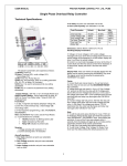
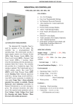
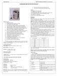
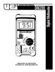
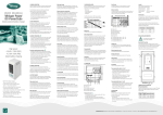
USER MANUAL
PROTON POWER CONTROL PVT. LTD., PUNE
DUAL PUMP STARTER PANEL
Product Code: PSP 33M
WORKING:
In normal running mode, display shows
1. r-HP--R phase Current
2. y-HP--Y phase Current
3. b-HP--B phase Current
4. r-Rp--R phase Current
5. y-rP--Y phase Current
6. b-rP--B phase Current
7. < Faults if any>
• oL HP--Over load HP
• Ub HP--Unbalance HP
• oL rP-- Over load rP
• Ub rP-- Unbalance rP
• SP HP--Single phase HP
• SP rP--Single phase rP
All the protections like Overload,
current unbalance are activated in Auto
as well as manual mode. Auto/ Manual
selection is done from front switch. In
any mode, if the faults are present
controller immediately turns off the
motor having the fault. The motors can
be restarted by resetting the fault by
pressing the ‘Decrement’ key.
In manual mode there are two
separate switches, one for each motor
to turn on and off. If the supply is within
the range and there is no fault condition,
an ON timer starts decrementing to zero
and motor relay is turned ON. This relay
interlocks with the Pump On signal.
After the Pump motor is switched on, if
any unhealthy condition occurs, fault
LED start blinking up to trip delay time
and then the is Relay is turned OFF.
Fault LED continuously glows if the
faulty condition persists.
Features:
• Three digits 7 segment bright display for
current.
• Calibration: using front keys.
• User Programmable.
• Password protected set parameters.
• Inbuilt 3 Phase 10 A Contactor for load
control.
• Message Display for faults.
The Starter Panel has is solid state Current
Meters. It measures currents and provides
protection against overload for both the motors.
This is based on a Microchip, programmed for
the
application.
The
Meter’s
supplied
preprogrammed for operation and can be
directly installed.
Specifications:
Nominal Input Current: - 0-9 A per Phase.
Accuracy:
Current: - 0.25% ± 1 dgts.
Resolution:
Current: - 0.01 A
Environmental:1] Working Temp
: 0 to 55º C
2] Storage Temp
: 10 to 70º C
3] Relative humidity
: 0 – 95 % NonCondensing
4] Warm up time
: 10 Sec
Enclosure:
1] Mounting
2] Enclosure
3] Terminal
LED Indications:
RED LED: Motor 1 (RWP) and Motor2
(HPP): Over Load, Current Unbalance,
and Single Phase Faults.
Green LED: If auto Mode Green LED
turns ON for manual mode Green LED
is turned off And on LED display ‘MAN’
is displayed.
KEYS:
• SET : This key is used to change the
controller from RUN mode to
• FUNCTION mode for parameter setting
• INC
: Up scroll the parameter &
: Panel mounting. (Cut Out Size:
182(H) X 92(W)
: 105 (W) X 200 (L) X 193 (H)
mm.
: Screw ON Terminals.
1
USER MANUAL
PROTON POWER CONTROL PVT. LTD., PUNE
parameter value.
: Down scroll the parameter &
parameter value, For manual
reset of Fault.
Note: To Load default parameter Press INC key
on power ON.
Front Switches:
1. Auto / Manual selection switch.
2. RWP (Motor1) manual ON/OFF control
3. HPP(Motor 2) manual ON/OFF control
•
SPP fault for the same is disabled for the motor
which is selected as single phase. Current,
displayed will be of the connected phase.
DEC
SETTINGS:
Sr. Parameter
No
1
Over Load
: oLHP
2
Over Load
: oLrP
3
Unbalance
Current
: ubHP
4
Unbalance
Current
: ubrP
5
Over Load
trip Delay
: oL trp
6
Unbalance
Current
trip Delay:
ub trp
7
HPP Motor
ON Delay
: HPon
8
RWP
Motor ON
Delay
: HPon
9
HPP
Single/Thr
ee Phase *
10 RWP
Single/Thr
ee Phase *
11 Display
Currents
Enable
: dISP (If
disabled,
shows
AUTO
/
MAN
selection)
Mi
n
2.0
Max
Default
Unit
13.0
5.0
Amp
2.0
13.0
5.0
Amp
20
50
40
20
50
40
1
30
5
% of
Over
Load
% of
Over
Load
sec
1
30
5
sec
5
300
10
sec
5
300
10
sec
CONTROLLER FUNCTIONS:
Password is 11 for Overload setting, 20 for rest
parameter settings & password 5 is for
displaying currents for one cycle.
Procedure to change parameter settings:
1. Press SET key.
2. Enter Correct Password.
3. Wait to check password.
4. Using UP Arrow & down Arrow key user
can change setting parameters.
5. Press UP Arrow Key to increment
parameter value up to maximum limit.
6. Press down Arrow key to decrement
parameter value down to minimum limit.
7. To save the settings (value) wait for five
seconds
Note:
1. Calibration setting is for Factory
Setting only.
2. For manual reset of faults, press
Decrement Key.
3. Password 5 is applicable only
When display current enable mode is
disabled.
4. To Load default parameter Press
INC key on power ON.
Field Terminal Layout:
Back View:
R
1P
3P
3P
NA
1P
3P
3P
NA
no
yes
yes
NA
1PHASE HPP OUTPUT
3PHASE HPP OUTPUT
AC SUPPLY
3P 415V 50Hz
Y
TO HPP
CONTACTOR
C
2
NO
B
N
R
TO RWP
CONTACTOR
C
NO
Y
B
HPP ON
C
NO
1PHASE RWP OUTPUT
3PHASE RWP OUTPUT
N
R
B
Y
N
MPV
POWER
DOSING
PUMP
L
L
N
N
USER MANUAL
PROTON POWER CONTROL PVT. LTD., PUNE
FLOWCHARTS:
H
ENTER
PASSWORD
=5
IF FUNCTION
KEY PRESSED
NO
SET OL TRIP
DELAY?
(DEFAULT 5s)
NO
ENTER
YES
FUNCTION
MODE
SELECTED
DISPLAY HPP/RWP
CURRENT
ENTER
PASSWORD
RUN MODE
SET UB TRIP
DELAY?
(DEFAULT 5s)
NO
DECREMENT OR
INCREMENT(1s-30s)
ENTER
YES
B
DECREMENT OR
INCREMENT(1s-30s)
SET HPP ON
NO
DELAY?
(DEFAULT 10s)
YES
DECREMENT OR
INCREMENT(5s-100s)
NO
PASSWORD
=11
YES
G
SET RWP ON
DELAY?
(DEFAULT 10s)
DISPLAY
SETTING
PARAMETERS
NO
NO
RWP MOTOR
SET?
DEFAULT 3PH
DECREMENT OR
INCREMENT(2A-13A)
NO
SET
OLRP?
DEFAULT 5A
NO
DISPLAY
SET?
DEFAULT YES
DECREMENT OR
INCREMENT(2A-13A)
NO
SET
UBHP?
DEFAULT 40%
NO
PASSWORD
CHANGE?
DEFAULT 11
DECREMENT OR
INCREMENT(20%-50%)
DECREMENT OR
INCREMENT(YES/NO)
ENTER
YES
YES
DECREMENT OR
INCREMENT(1PH-3PH)
ENTER
YES
YES
DECREMENT OR
INCREMENT(5s-100s)
ENTER
YES
ENTER
YES
SET
OLHP?
DEFAULT 5A
ENTER
YES
NO
DECREMENT OR
INCREMENT(0-9999)
YES
YES
FUNCTION
TIME OUT?
SET
UBRP?
DEFAULT 40%
NO
NO
G
DECREMENT OR
INCREMENT(20%-50%)
YES
YES
RUN MODE
H
TM
PROTON
PROTON POWER CONTROL PVT. LTD.
S. NO. 28, JAGTAP DAIRY,
PIMPLE NILAKH, PUNE – 411027.
TEL: 020-2727 0800, 27276777
TEL/FAX: 020-2727 0100
MOBILE: 9764885010/9422009655
E-MAIL: [email protected]
[email protected]
3
B