1
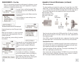
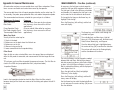
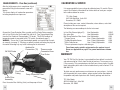
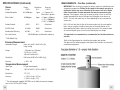
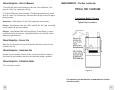
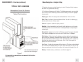
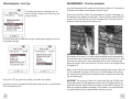
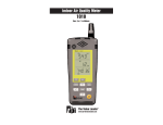
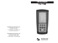
Flue Gas Analyzer
716 / 716N
Test Products International, Inc.
9615 SW Allen Blvd., Ste. 104
Beaverton, OR 97005
Tel: 503-520-9197 Fax: 503-520-1225
www.tpi-thevalueleader.com
Test Products International, Ltd.
342 Bronte Road South, Unit #9
Milton Ontario Canada L9T5B7
Tel: 905-693-8558 Fax: 905-693-0888
The Value Leader
www.tpi-thevalueleader.com
TM
Contents
Introduction........................................................1
General Overview.................................................1, 2
Instrument Overview............................................. 3 ~ 7
Front View...............................................3
Keypad...................................................4
Back View...............................................5
Side Views..............................................6
Top View................................................ 7
Basic Analyzer Functions....................................... 8 ~ 10
Charging The Analyzer................................ 8
Turning The Analyzer On ............................ 9
Turning The Analyzer Off............................. 10
Display Backlight..................................... 10
Combustion Analysis Overview.................................11
Measurements.................................................... 12 ~ 28
Flue Gas................................................ 12 ~ 21
Typical Test Results...................................22
Temperature & Pressure.............................23 ~ 24
Tightness Test......................................... 25 ~ 26
CO Room Test..........................................27
Combustible Gas Leak Detection...................28
Menu Navigation................................................. 29 ~ 32
Memory................................................ 29
Fuel Type................................................30
Analyzer Setup.........................................31
Units of Measure, Sensor Info, Instrument Info. 32
Specifications..................................................... 33 ~ 34
Calibration & Service............................................ 35
Warranty........................................................... 35
Appendix A
General Maintenance & Function Tests............36 ~ 38
Appendix B
A773 Sulfur Filter Installation & Maintenance....39 ~ 40
Appendix C
Error Codes and Troubleshooting....................41~ 42
Appendix D
Testing for Carbon Monoxide in Ambient Air......43
Appendix E
Carbon Monoxide Limits in Ambient Air Chart....44
Appendix F
Carbon Monoxide Facts...............................45
Appendix G
Battery Replacement..................................46
Notes:
Notes:
Introduction
Thank you for purchasing TPI brand products. The TPI 716 Flue Gas
Analyzer is a state of the art, easy to use analyzer designed not only to
display and calculate the required readings from a flue but also to
cover most of the other measurements associated with combustion.
The instrument is ruggedly constructed and comes with a 3 Year unit
and 2 Year sensor Guarantee.
General Overview
The TPI 716 combustion analyzer uses state of the art electrochemical
sensors. This sensor technology provides the longest lasting, most
accurate and reliable means for performing combustion tests. The sensors in your analyzer will need to be replaced periodically and calibration is recommended once every year.
Electrochemical sensors by nature are always active. Therefore the
time the analyzer is off and not being used must be taken into account
when determining sensor life. The sensors in your analyzer are warranted for two years. This warranty does not cover sensors damaged
through misuse of the analyzer.
You should keep the battery of your 716 charged so power is constantly being supplied to your sensors.
The following guidelines will help prevent damage to your sensors:
Always use the mini pump filter when testing flue gases.
Always periodically check and replace the mini pump filter as needed.
Always make sure the in-line filter / water trap is installed properly.
Always periodically check and replace the in-line filter as needed.
Always remove water or condensation from the inside of the in-line filter / water trap assembly prior to performing tests.
Always use the optional oil filter (p/n A773) when performing tests on
oil burning equipment unless you are using the 716N. Do not use the
A773 with the 716N because the A773 will filter out Nitric
Oxide (NO).
1
General Overview (Continued)
Never over saturate your sensors by performing tests on equipment
with gas levels beyond the capability of you analyzer.
Always keep the A795 water trap / filter assembly clean and replace the
filter as necessary. Replacement filter part number is A794F.
This manual will guide you through the functions of the TPI 716 which
will give you many years of reliable service.
Your TPI 716 Flue Gas Analyzer comes complete with the following
standard accessories:
( ) Denotes part number
•
•
•
•
•
•
•
•
•
•
•
•
•
•
•
•
•
•
TPI 716 Analyzer
Combustible Gase Leak Probe (A806)
Rubber Boot (A765) 1 each installed on analyzer
Soft Carrying Case (A768) - 1 each
Flue Sampling Probe (A770) - 1 each
In-Line Filter / Water Trap installed on Flue probe (A795) - 1 each
Disc water filter installed in water trap (A794W) - 1 each
Spare In-Line Filter - 1 each (A794F is a package of 5 filters)
Temperature Probe (GK11M) - 1 each
Battery Charger (A766) - 1 each
Mini Pump Protection Filter Assembly (A763) - 1 each
Exhaust Spigot Removable (A764) - 1 each
Pressure Tubing (A774) - 1 each 6’ piece
Static Pressure Tips (A776) - 2 each
1/4” barbed to 1/8” NPT fitting (A603) - 2 each
Gas Valve Adapter (A611) - 1 each
Adapter Tubing (A791) - 1 each 4” piece
Instruction Manual
Your TPI 716 Flue Gas Analyzer has the following options available:
• A807 PC Software and cable for communication to a PC.
• A740 infrared printer (Included with 716A740)
2
Notes:
Appendix G: Battery Replacement
When the battery in your analyzer will no longer charge, no longer hold a
charge, or if beeping is heard while charging this is usually an indication the
battery pack requires replacement.
Instrument Overview
For best results use a TPI replacement battery part number A007. The battery in
your analyzer is 3.6V NiMH 1600mAh rated. Never replace the battery with any
other type of battery or damage to the charge circuit will result.
The battery pack is replaced as follows:
1. Turn the analyzer over and locate the phillips head battery cover screw. See
picture below.
Rubber
Boot
LCD
Display
Keypad
Battery Cover Screw
Battery Cover
Front View
2. Loosen the screw. Pull out on the screw to remove the battery cover.
Rubber Boot
Protects the instrument from accidental damage
3. Remove the old battery pack from the battery compartment. Pull the battery
wire out of the connector.
Display
Large graphical backlit LCD Display
4. Install the new battery pack by inserting the connector from the battery pack
into the connector on the analyzer. Install the battery pack into the battery compartment.
Keypad
Selects all available functions
4. Re-install the battery cover by fitting the bottom part in first.
5. Tighten the battery cover screw.
46
NOTE: When selecting oil as fuel be sure to use the optional
oil filter (A773) or readings could become erratic. See
Appendix E for installation instructions.
Do NOT use the A773 with the 716N analyzer.
3
Keypad
Appendix F: CARBON MONOXIDE FACTS
Blue Soft Keys - The function of these keys is shown in the
lower part of the display and changes depending on what
menu the analyzer is in.
In the picture center soft key controls the start function and
the left and right soft keys are disabled.
Carbon Monoxide (CO) is invisible, odorless, and tasteless. It is the byproduct of
combustion and levels are elevated when there is incomplete combustion.
Sources of CO include:
Unvented kerosene and gas space heaters
Leaking chimneys & furnaces
Gas water heaters
Back drafting from furnaces
Wood stoves& fireplaces
Gas Stoves
Automobile exhaust
Tobacco smoke
Carbon Monoxide is picked up quickly in the body by red blood cells. At high levels of CO the body replaces oxygen with carbon monoxide.
Up Arrow Key This key is used
to scroll up in
menus.
Down Arrow
Key - This key
is used to scroll
down in menus.
The most common symptoms of CO poisoning are headache, dizziness, weakness, nausea, vomiting, chest pain, and confusion. High levels of CO inhalation
can cause loss of consciousness and death. Unless suspected, CO poisoning can
be difficult to diagnose because the symptoms mimic other illnesses.
People who are sleeping or intoxicated can die from CO poisoning before ever
experiencing symptoms.
Please see the next page for a list of exposure times and symptoms.
Home Key - This key is
used to return to the
Main Menu from any
other menu.
4
Back Key - This key is
used to go back one
menu level.
On/Off Key - This key is
used to turn the analyzer on and off.
45
Appendix E: Carbon Monoxide in Ambient Air Chart
Back View
This chart contains maximum exposure levels and times for carbon monoxide.
This is a general guideline only. It is recommended you check with your local
government for guidelines in your area.
Calibration and
Information
Label
Rubber
Boot
Battery
Compartment
Calibration and Information Label: Displays calibration information and
serial number
44
Battery Compartment:
Holds rechargeable battery
Rubber Boot
Protects the instrument
5
Side Views
Appendix D: Testing for Carbon Monoxide in Ambient Air
The 716 can be used to test for carbon monoxide in ambient air. For example
tests can be performed in work spaces and living areas like offices and houses
to ensure safety.
Exhaust
Port
1. Following the steps outlined on page 8, turn the analyzer on in a clean air
environment away from the area to be tested,
2. Select “Measurement” from the Main Menu. Select “Flue gas” from the
Measurements Menu. After a purge cycle the display below will be seen.
Ambient CO levels will be seen in the top line
of the display. (CO in ppm)
Infrared
Window
Rubber
Boot
Exhaust Port
Port for connection of Exhaust Adapter
Infrared Window
Window for sending stored data to IR Printer
Rubber Boot
Protects the instrument from accidental damage
3. Connect the Pump Protection filter to the analyzer.
4. Begin testing for carbon monoxide. Move from space to space to detect any
CO that may be present. The CO reading will be seen in the top part of the display.
5. If necessary, the flue probe can be attached to test in ducts and plenums.
6. Refer to the chart on page 50 for a list of exposure times and levels of carbon
monoxide in ambient test applications and page 51 for carbon monoxide facts.
7. When testing is complete, turn the analyzer off as outlined on page 8.
6
Measurements - Temperature & Pressure
43
Appendix C: ERROR CODES & TROUBLESHOOTING (Continued)
Problem
Efficiency reading incorrect
Readings are erratic when working
on oil fired equipment.
Possible Cause
Corrective Action
NET efficiency selected.
Select GROSS efficiency. See page
13.
Ambient temperature probe not
plugged in to T2.
Plug ambient probe into T2. See
page 14.
Incorrect fuel selected.
Select the proper fuel for the equipment being tested. See page 13.
Oil filter not installed or installed
incorrectly (716 only).
One or all of the following parameMeasured values are such that the
ters; Ratio, CO air free, excess air,
calculated values of these parameand efficiency read and print dashes. ters are out of range.
Top View
Charger
Socket
Make sure the optional sulfur filter
(A773) is installed. See Appendix B.
Redo combustion test. Since these
are calculated values, the measure
values must be within certain levels
for these to display. If the measured
oxygen level is above 19.9% these
parameters won’t read.
USB Port
P(+)
Port
These parameters might not display
or be applicable in some tests.
Pressure prints as “N/A” on my com- During combustion analysis if a pres- Perform the combustion test and
bustion analysis print out.
sure measurement is not being made also connect the manometer and
this parameter will print as not being monitor pressure.
used.
Battery will not charge or hold a
charge.
Defective charger or battery.
T1 Socket
T2 Socket
Gas
Sample
Port
P(-)
Port
Charger Socket
Connection for 220V/115V charger
T1 Socket
Connection for thermocouple plug on flue probe
Connection for any 'K' type thermocouple probe
Replace the charger or battery.
Send to TPI for service.
Beeping noise heard during charging.
Defect in charging circuit or shorted
battery.
Analyzer won’t turn off
Oxygen and/or carbon monoxide lev- Allow the analyzer to purge longer.
els outside limits.
Disconnect from the charger and
contact TPI at 800-368-5719.
T2 Socket
Connection for ambient 'K' type thermocouple probe
Connection for any 'K' type thermocouple probe
Pressure sensor will not zero.
42
Pressure sensor needs to be reset.
Gas Sample Port
Connection for Mini Pump Protection Filter and Flue
Probe
P (+) Port
P (-) Port
Connections for Pressure Tubing
USB Port
Connection for optional A807 cable for communication
to a PC or connection for A806 combustible gas leak
detection probe.
Send to TPI for calibration.
7
BASIC ANALYZER FUNCTIONS
Charging The Analyzer
Appendix C: ERROR CODES & TROUBLESHOOTING
Code
Displayed
Plug the charger into the charger socket on the instrument (see page 7).
When the charger is plugged in the battery level display will turn on. This display indicates the analyzer is being charged and the status of the charge.
Flow
Error
Code Definition
Oxygen sensor failed to initialize
Dirty or blocked filter(s).
Replace filter(s). See
Appendix A.
Worn pump.
Return to TPI for service.
Flue probe connected to 716 Disconnect probe and
restart.
prior to power up.
716 did not purge completely Purge for 20 minutes and
restart.
from last sample.
Worn or defective oxygen
sensor.
The charge level is represented in
graph form as well. The charge is displayed in percentage. (0 to 100%)
InIt
CO
Err
Corrective Action
Pump not drawing sample at Blockage / kink in flue probe Check and rectify. See
correct flow rate.
hose.
Appendix A.
The plug symbol confirms the analyzer is connected to the charger. The
battery symbol shows the charge
level when the analyzer is on too.
InIt
O2
Err
Possible Causes
Carbon monoxide sensor
failed to initialize.
Return to TPI for sensor
replacement.
Flue probe connected to 716 Disconnect probe and
prior to power up.
restart.
716 did not purge completely Purge for 20 minutes and
from last sample.
restart.
Worn or defective carbon
monoxide sensor.
Return to TPI for sensor
replacement.
During operation the analyzer will display charge status and battery condition in
the top right corner of the display.
Battery is at full capacity.
Lo
bat
Low battery.
Battery needs to be charged. Charge battery. If the battery
won’t hold a charge, replace
the battery.
oFL
Overflow indication. The
pressure being measured is
outside the maximum measurement capability.
Pressure being measured is
too high or low.
Battery is at 2/3 capacity.
Battery is at 1/3 capacity. The charger should be connected soon.
Battery is very low and needs to be recharged immediately
oFL
Indicates the analyzer is connected to the charger.
If a beeping noise is heard during charging disconnect the charger. This is an
indication the battery pack needs to be replaced. Please see Appendix G for battery replacement instructions.
8
oPEn
Remove pressure source.
Pressure sensor damaged or Return to TPI for service.
defective.
Overflow indication. The tem- Temperature being measured Remove pressure source.
perature being measured is is too high or low.
outside the maximum measurement capability.
Unable to read thermocouple Temperature probe not connected to input.
(temperature).
Worn temperature sensor.
Connect temperature probe
to analyzer.
Replace temperature probe
or flue probe.
41
Appendix B: A773 SULFUR FILTER INSTALLATION & MAINTENANCE
4. Beginning on the “Flue Probe” side of the A773 sulfur filter, pull the yellow
thermocouple cord out of the channel of the flue probe tube. Pull out approximately the length of the water trap that was removed.
5. Being careful not to cut the yellow cord, cut out a section of the flue probe
tubing the length of the water trap on the “Flue Probe” side of the A773 sulfur filter. (See picture below)
Turning The Analyzer On
Always: - Before turning on please ensure nothing is connected to the Gas
Sample Port (see page 7)
Press and hold the ON/OFF key down for approximately 3 seconds. The 716
will beep and the initial start up screen will be displayed.
The initial start up screen displays the
following information:
Model number of the analyzer
Firmware version
Firmware date
Serial number of the analyzer
6. Install the water trap in the flue probe hose where the piece was cut out. Make
sure the water trap is positioned correctly. The water trap lid should face the
“Hose End” side of the hose. (See picture below)
Last calibration date of the sensors
Note: The NO sensor calibration date
will only display for 716N models.
After the initial start up screen displays for approximately 5 seconds the Main
menu will be displayed.
The main menu displays the following
information:
Battery status
A773 SULFUR FILTER MAINTENANCE:
Date (dd.mm.yyyy format) and time
(24hr clock)
The A773 should be replaced when most of the pellets become discolored, usually white or black.
Menu Selections
If the A773 begins to trap condensate and fill with water but the pellets are not
discolored to the point replacement is required, it should be removed and allowed
to dry. Once it is dry it can be reused.
Left blue soft key activates Bluetooth
(Only models equipped with this option.)
Center blue soft key confirms selection
40
9
Turning The Analyzer Off
Appendix B: A773 SULFUR FILTER INSTALLATION & MAINTENANCE
Always: - Before turning off return the instrument to a clean air environment
and allow the Carbon Monoxide level to return below 15ppm and the Oxygen
level to return to 20.9% (± 0.3%) Press the Power Key to turn the instrument
off:- NOTE The Instrument will not allow itself to be switched off if the CO is
above 15ppm
When the 716 is turning off the following screen is seen:
USE THE A773 ONLY WITH THE 716. DO NOT USE WITH THE 716N.
When using a 716 and performing combustion tests on oil fired equipment it
is important to use the optional A773 sulfur filter. Failure to do so can result
in incorrect and readings. This filter also protects the sensors from the
affects of sulfur. The A773 does not have to be removed when working with
other types of fuels.
PROCEDURE
The instrument has an auto shut off factory set for 10 minutes should no keys have
been pressed for this period and the CO
level is below 15ppm. The auto power off
can be set to a different time or disabled.
Please refer to Menu Navigation - Analyzer
Setup on page 31.
If the CO level is close enough to 0ppm
and the O2 level is close enough to 20.9%
the analyzer will display “Skip”. This
allows you to skip the purge by pressing
the middle soft key.
1. Begin with the water trap section of the flue probe oriented as shown in the
picture below.
2. Remove the water trap from the flue probe hose. (See picture below)
Display Backlight
The display backlight is factory set to Auto. A sensor located on the side of
the analyzer detects the amount of ambient light and automatically adjusts
the backlight intensity.
3. Insert the A773 sulfur filter flue probe tube where the water trap was
removed. (See picture below)
The backlight can be manually adjusted to a desired level by the user. Please
refer to Menu Navigation - Analyzer Setup on page 31.
10
39
Appendix A: General Maintenance (continued)
Flue Probe Integrity Check
NOTE: Perform this check after performing the Pump Operation Check outlined
on the previous page.
1. Turn the analyzer on as outlined on page 8. Do not connect anything to the
inlet. Wait until the analyzer has completed the initial purge and sensor check
and is operating normally prior to proceeding to step 2.
2. Connect the A763 mini pump protection filter and flue probe assembly to the
inlet of the analyzer and the yellow thermocouple connector to input T1.
3. Repeatedly press the Scroll/Enter key until temperature is displayed. If the
displayed temperature is approximately the ambient temperature the thermocouple is operating properly and you may proceed to the next step to continue
the test. If the displayed temperature is “OL” the thermocouple is open and the
probe is in need of factory service.
4. Cover the end of the flue probe with a small piece of tube and pinch the end
close. After a short period of time the analyzer should display “Flow Error” and
a rapid beeping should be heard. If this happens the flue probe his operating
properly and the integrity test is complete. If the analyzer does not display “Flow
Error” this is an indication of a possible leak somewhere in the flue probe and
you may proceed to the next step for further tests.
5. Pinch the hose below the handle of the flue probe. If the analyzer displays
“Flow Error” there is a leak in the handle assembly and the probe needs to be
factory serviced. If the analyzer does not display “Flow Error” proceed to the
next step for further tests.
COMBUSTION ANALYSIS OVERVIEW
Performing combustion analysis is very important to the overall safety and
efficiency of heating equipment. The following guidelines and descriptions are
generic and meant to provide you with a basic understanding of combustion
testing. TPI always recommends you contact the manufacturer of the device
under test, obtain information specific to the device, and follow the procedures and safety guidelines for performing tests and affecting repairs.
In general, for most applications, flue gas samples should be taken prior to
the draft diverter or any other opening that allows room air to enter the system. This prevents room air from mixing with gases in the flue and diluting
the test sample. To ensure accurate and consistent combustion tests, it is
important gas and temperature samples be taken at the same location. This is
easy with the TPI flue probe because the temperature sensor is an integral
part of the probe.
Prior to taking a sample, the device under test should be on and operating.
Putting the flue probe in the sample area prior to starting the device may
cause saturation of the sensors due to the higher initial concentration of carbon monoxide that may be encountered upon start up. If this happens, allow
your analyzer to purge in fresh air until the carbon monoxide level returns to
0 ppm and the oxygen level returns to 20.9%. This may take more than an
hour depending on how saturated the sensors are.
The figures on pages 16 through 18 show locations for performing tests on
commonly encountered equipment. Remember to consult with the manufacturer of the device under test for specific test information.
Pressing the Func Key enables access to the different functions available on
the 716. The default function is Combustion Analyzer. Other available functions are: Thermometer, Manometer/Tightness Test, Combustible Gas Leak
Detector, and Date / Time display.
6. Pinch the hose between the analyzer and the water trap. If “Flow Error” still
does not display there may be an internal leak, pump problem, or other issue
and the analyzer needs to be factory serviced. If “Flow Error” is displayed there
is a leak in the water trap assembly and the water trap assembly should be
checked as outlined on page 36 & 37.
38
11
MEASUREMENTS - Flue Gas
Note: It is recommended you perform routine general maintenance on your
analyzer to ensure proper function. Please refer to Appendix A for general
maintenance schedule and function tests.
Turn the 716 on as outlined on page 8. After
the initial start up screen the Main Menu will
be displayed.
Using the Arrow keys select Measurements by
highlighting it.
Press the Enter key (center soft key) to confirm the selection.
Appendix A: General Maintenance (continued)
Filter Check Continued
The other two filters are located in the water trap. The main filter is the A794F
particle filter. This filter stops debris and dust from traveling down to the analyzer. The secondary filter is the A794W water block filter. This filter stops flow in
the event the water trap fills with condensate. Refer to the picture below.
Water trap bowl. A794
water trap pictured. A795
water trap is similar but
longer
A794F
Particle Filter
A794W
Water
Block Filter
A794D Filter
Spacer Disc
The Measurements menu will be displayed.
Water trap lid. O-ring is
located in the lid recess
Using the Arrow keys select Flue gas by high
lighting it.
Make sure the analyzer is in a clean air environment with only the pump protection filter connected to the input.
Open the water trap and look at the A794F particle filter. The filter will typically
get dirty from the inside first. If the filter is dark on the inside a replacement filter should be installed.
Press the Enter key (center soft key) to confirm
the selection.
If the A794F is clean but saturated with water a replacement should be installed
to ensure proper flow. The saturated filter can be left to dry and reused later.
Pump Operation Check
The pump will start and the Zeroing screen will
display. The analyzer is initializing and self
testing the sensors during this 30 second
cycle.
1. Turn the analyzer on as outlined on page 8. Do not connect anything to the
inlet. Wait until the analyzer has completed the initial purge and sensor check
and is operating normally prior to proceeding to step 2.
The selected fuel type will be displayed and can
be changed as necessary (see pg 13).
2. Cover the analyzer inlet with your finger. The analyzer should display “FLO
ERR” and a rapid beeping should be heard.
The selected unit of efficiency is displayed
and can be changed as necessary (see pg 13).
If the analyzer does not beep and display “FLO ERR” this may be an indication
the flow sensor requires calibration, the pump is faulty, or there is an internal
leak. The analyzer should be returned for factory service.
If the analyzer is ready for use, “Skip” will
appear above the center soft key. Pressing this
will bypass the 30 second countdown.
12
37
Appendix A: General Maintenance
All combustion analyzers use consumable items such filters and probes. These
items are user serviceable and can be taken care of by the operator.
The consumable items that will require operator attention are the water trap / filter assembly, flue probe, pump protection filter, and ambient temperature probe.
The recommended maintenance schedule for your analyzer is as follows:
Maintenance Performed
Water trap Check
Filter Check
Pump Operation Check
Flue Probe Integrity Check
Thermocouple Probe Check
Frequency
Once per week (Once per day for analyzers
that see heavy use or are used in oil fired
applications)
Once per month (More often for analyzers
that see heavy use or are used in oil fired
applications)
Water Trap Check
Visually check the water trap for:
1. Cracks in the bowl.
2. Broken ears on the bowl where the lid locks on.
3. Broken ears on the lid.
4. Worn out o-ring on the lid.
5. Loose connection to the flue probe tubing.
Filter Check
Signs of dirty or water saturated filters are a slow pump, flow error displayed
when the flue probe is connected, and measurements that take longer than normal.
TPI analyzers use three filters to protect the pump and sensors. The first filter to
check is the A763 mini pump protection filter. (see picture below)
Inspection Window
MEASUREMENTS - Flue Gas (continued)
As necessary, the fuel type can be changed to
match the fuel type of the equipment under test.
The fuel type is used in the efficiency calculation
and therefore it is important the fuel type is correct in order for the calculation to be accurate.
To change the fuel type use the Arrow keys to
highlight “Fuel change”.
Press the Chang key (left soft key) and the fuel
menu will display.
The Arrow keys are used to scroll through the
available fuel types.
The available fuels are Natural gas, Light oil,
Heavy oil, LPG, Bituminous coal, Anthracite coal,
Coke, Butane, Wood (dry), and Bagasse.
Once the desired fuel type is highlighted press
the center soft key (OK) to confirm the selection.
The analyzer will return to the Zeroing display
and the countdown will continue.
The unit of efficiency can be changed as needed
between Nett and Gross. Nett eficiency doesn’t
take into account wet losses while Gross efficiency does. In the USA Gross efficiency is used. If
Nett is selected the efficiency will be displayed as
much higher than it is.
Press the right soft key (Next) to highlight
“Efficiency” in the display.
Pump Protection Filter
Look in the inspection window to check the filter. When the filter material
becomes dark, pull the black nose cone out of the tubing and replace the ball filter inside.
36
Press the Chang key (left soft key) and the efficiency menu will display.
Use the Arrow keys to select the desired efficiency unit and press the center soft key (OK) to confirm the selection.
13
MEASUREMENTS - Flue Gas (continued)
CALIBRATION & SERVICE
After the initial purge cycle is complete or skip is
pressed the Flue gas measurement screen will
display.
It is recommended that your analyzer be calibrated every 12 months. Please
consult Test Products International for further details or send your analyzer
to the address below for service.
This screen displays all combustion parameters
including temperature and pressure.
TPI / Attn. Repair
9615 SW Allen Blvd. Suite 104
Beaverton, OR 97005
Please include your name, contact information, return address, and a brief
description of the service required.
The following are consumable parts for the instrument:
Connect the Pump Protection Filter assembly and Flue Probe Tubing complete
with In-Line Filter to the Gas Sample Port and the 'K' Type Thermocouple Plug
from the Flue Probe into Thermocouple (T1) Socket. The GK11M ambient air
temperature probe is connected to the (T2) socket. (See below & page 7)
WARNING: - Ensure the 'K' type thermocouple probes are inserted into the sockets correctly (see page 7). The plugs are polarity marked and forcing the plug into
the socket the wrong way may result in damage to the instrument.
GK11M Probe
Ambient Air
Connection (T2)
Thermocouple
Connection from
Flue Probe
In-Line Filter Element (pkg of 5)
User Replaceable
Disc water filter
User Replaceable
Mini Pump Protection Filter Assem. User Replaceable
**Oxygen Sensor
User / Factory Replaceable
**Carbon Monoxide Sensor
User / Factory Replaceable
**Nitric Oxide Sensor
User / Factory Replaceable
**Sensor replacement requires calibration gas.
A794F
A794W
A763
A761
A760
A793
These items require periodic replacement as the analyzer is used.
Please see Appendix A on page 37 for general maintenance information.
WARRANTY
Your TPI 716 Flue Gas Analyzer is guaranteed free from defects in materials
and workmanship for 3 Years from the date of purchase. The sensors carry a
2 Year warranty. This guarantee does not affect your statuary rights. For additional information please refer to the included warranty card or contact TPI at
800-368-5719.
Flue Probe
Tubing
Pump Protection Filter
In-line Filter
Assembly
Press the center Blue Soft Key (Start) and the pump will start.
14
To obtain warranty performance or maintenance on your analyzer: - Include
with the product your name, address, phone number, written description of
the problem and proof of purchase date. Carefully package and return to:
TPI / Attn. Repair
9615 SW Allen Blvd. Suite 104
Beaverton, OR 97005
35
SPECIFICATIONS (Continued)
Gases
Oxygen
Carbon Monoxide
Nitric Oxide *
Range
0-25%
0-10,000 ppm
0-5000ppm
MEASUREMENTS - Flue Gas (continued)
Resolution
0.1%
Accuracy
+/- 0.3%
1 ppm
+/- 5 ppm or 5%
Whichever is greater
1ppm +/- 5ppm (<100ppm)
+/- 5% (<1000ppm)
+/- 10% (>1000ppm)
Carbon Dioxide
0-25%
0.1%
Calculated
CO/CO2 Ratio
0-0.999
0.001
Calculated
Combustion Efficiency
0-100%
0.1%
Calculated
Gas Leak Sensor
100-10,000 ppm (calibrated to methane)
IMPORTANT: Prior to taking a sample, the device under test should be on and
at operating temperature. Putting the flue probe in the sample area prior to
starting the device may cause saturation of the sensors due to the higher
initial concentration of carbon monoxide that may be encountered upon
start up. If this happens, allow your analyzer to purge in fresh air until the
carbon monoxide level returns to 0 ppm and the oxygen level returns to
20.9%. This may take more than an hour depending on how saturated the
sensors are.
Drill a 1/4 inch hole into the flue of the device under test. For most applications, flue gas samples should be taken prior to the draft diverter or any
other opening that allows room air to enter the system. This prevents room
air from mixing with gases in the flue and diluting the test sample.
It is important to use manufacturers recommended test locations whenever
possible.
*716N Model Only
Pressure Measurement
Selectable Ranges
mbar, psi, inH2O, mH2O, kPa, hPa,
inHg, mmHg
Range
- 150 mbar to + 150 mbar
-15 kPa to + 15 kPa
-60 inH2O to 60 inH2O
Resolution
0.01 mbar, 0.001 kPa, 0.001 inH2O
Accuracy
+/- 0.5% fsd
Refer to the figure below for calculating the sample hole location.
The figures on the following pages show typical test locations on commonly
encountered equipment.
Temperature Measurement
Input Type
K-Type thermocouple
Range
-58°F to 1832°F (-50°C to 1000°C)*
Resolution
1°F (1°C)
Accuracy
+/- (0.3% of rdg + 2°F) or
+/- (0.3% of rdg + 1°C)
* The thermocouple supplied (GK11M) has the ability to measure temperatures in the -50°F to 950°F range.
34
15
MEASUREMENTS - Flue Gas (continued)
TYPICAL TEST LOCATIONS
Atmospheric Gas Fired Fan Assist Boiler / Furnace
SPECIFICATIONS
Instrument
Operating Temperature Range
14°F to +122°F (-10°C to +50°C)
Battery / Battery Life
Rechargeable Ni-MH / > 6 Hours
Charger Input Voltage
115V or 230V : 50/60 Hz AC
Fuels
Natural Gas, LPG, Light Oil, Heavy Oil,
Bituminous Coal, Anthracite Coal, Coke,
Butane, Wood, Bagasse
Pressure Ranges
mbar, psi, inH2O, mH2O, kPa, hPa,
inHg, mmHg
Display
Backlit Graphic LCD
Data Storage
100 sets of readings, multiple pages
Single Logging
150 sets of time stamped readings
Time & Date
24 Hour Real Time Clock
Dimensions
7.8” (200mm) x 3.5” 90mm x 2.4” (60mm)
Weight
1.1lbs (500g)
Conforms to
BS7927 (and the draft BS7967)
Typical Test Locations
Flue Temperature Probe
Figure 1
Construction
Pistol Grip with Stainless Steel Shaft
Hose Length
8.2’ (2500mm)
Insertion Length
7.9” (200mm)
'K' Type Thermocouple Accuracy
+/- 0.3% of fullscale, +/- 2°F (1°C)
Maximum Temperature
1472°F (800°C)
It is important to use manufacturers recommended test locations
whenever possible.
16
33
Menu Navigation - Units of Measure
1. From the main menu use the Arrow keys to select “Units of Measure” and
press the “Enter” key (center blue soft key).
2. The Units of Measure menu will display. The following parameters are accessible in this menu. Use the Arrow keys and center blue soft key to select the appropriate parameter.
Temperature - Select between °C and °F for temperature measurements.
MEASUREMENTS - Flue Gas (continued)
TYPICAL TEST LOCATIONS
Condensing Boiler / Furnace
Typical Test Locations
Pressure - Select between mbar, psi, inH2O, mmH2O, kPa, hPa, inHg, and mmHg
units of measure for pressure readings..
Efficiency - Select between Nett and Gross efficiency. Gross efficienc is used in
the USA and factors in wet losses. Using Nett efficiency in the USA will result in
abnormally high efficiencies.
Menu Navigation - Sensor Info
Allows the user to see the last and next calibration date of the sensors that are
installed in the 716.
Menu Navigation - Instrument Info
Provides the serial number, firmware version, and firmware date for reference.
Also shows the last calibration date of the unit and batter voltage / condition.
Menu Navigation - Calibration Mode
This is for factory use only.
Figure 2
It is important to use manufacturers recommended test locations
whenever possible.
32
17
MEASUREMENTS - Flue Gas (continued)
TYPICAL TEST LOCATIONS
Atmospheric Forced Air Furnace
Typical Test Locations
Menu Navigation - Analyzer Setup
1. From the main menu use the Arrow keys to select “Analyzer Setup” and press
the “Enter” key (center blue soft key).
2. The Analyzer Setup menu will display. The following parameters are accessible
in this menu. Use the Arrow keys and center blue soft key to select the appropriate parameter.
Display type - Allows the display to be switched between 8 line and 4 line.
Date / Time - Used to set the current date and time. The date is in dd:mm:yyyy
format and the time is a 24 hour clock.
Contrast - Lighten or darken the display contrast.
Backlight - Adjust the backlight level from off to full brightness or set it to auto
and the 716’s internal sensor will control the backlight brightness depending on
ambient light.
Alarm limits - Set the level at which the CO alarm sounds. The level is adjustable
from 10ppm to 3000ppm and can be turned off. Default level is 2000ppm.
Print Header - Enables the two line header on printouts to the infrared printer to
be set with your companies information. After pressing “Enter” you will be asked
for a password. Enter “7160” and press “OK”. Select Header Line 1 and then use
the Arrow keys to enter line one of the header. Press “Enter” then repeat the
process for line 2 of the header.
Auto Power - Enables the auto power off time to be set. The timer can be disabled
or set to one of the following times; 5, 10, 20, 30, or 60 minutes. If a key has not
been pressed during the time set, the analyzer will automatically begin to turn off.
Test all exhaust ports at the
top of the heat exchanger.
Memory - Enables memory maintenance as outlined on page 29.
Figure 3
It is important to use manufacturers recommended test locations
whenever possible.
18
31
Menu Navigation - Fuel Type
1. From the main menu use the Arrow keys to
select “Fuel Type” and press the “Enter” key (center blue soft key).
MEASUREMENTS - Flue Gas (continued)
Insert the flue probe into the sample hole of the device under test. The probe tip
should be in the middle of the flue pipe or exhaust stream.
Ensure the In-Line Filter / Water Trap hangs below the analyzer in the proper vertical position when readings are being taken. Failure to comply reduces the effectiveness of the water trap and may result in damage to the instrument. Refer to
the pictures below for correct and incorrect use.
2. Use the Arrow keys to select the fuel type. Scrolling down displays the rest of
the available fuel types.
WARNING: - Should the CO reading rise above 2,000ppm a continuous series of
Alarm Beeps will be heard. The Probe should immediately be disconnected from
the instrument and the instrument returned to a clean air environment. This Alarm
alerts the user that there is a high concentration of CO, and this procedure will
protect the sensors within the instrument. The alarm level can be changed. Please
see Appendix D
Make sure to check the water trap periodically during testing to ensure it does not
fill with condensate and empty it as necessary. If the filter begins to fill during a
test, open the lid and empty out the condensate. After closing the lid, allow readings to stabilize again.
3. press the “OK” key (center blue soft key) to confirm the selection.
Fuel type can also be changed from the flue gas zeroing screen as outlined earlier
in this instruction manual.
30
IMPORTANT: The water trap is fitted with a water block filter (p/n A794W) in the
lid to prevent water from flowing down into the pump. If the water trap fills the
water block filter will stop the flow to the analyzer and FLO ERR will display. The
water trap should be emptied immediately if this happens. The water block filter
may need to be dried out or replaced before testing can resume.
19
MEASUREMENTS - Flue Gas (continued)
Allow the readings to stabilize. Multiple parameters can be seen in the display.
• Carbon Monoxide (CO) reading in parts per million (ppm)
• Carbon Dioxide (CO2) figure in percentage (%)
(calculated)
• CO/CO2 (Ratio) figure. The 716 calculates this
number by first converting the CO2 measurement from percentage to ppm. The formula for
this conversion is: CO2ppm=(CO2%*10,000).
This ratio is not used in any other calculations.
10,000ppm = 1%
• Oxygen (O2) reading in percentage (%)
• Excess Air (X Air) in percentage
Menu Navigation - Memory
From the Main menu there are several sub menus that allow analyzer set up,
memory maintenance and other parameters to be accessed. Here is a list of each
and what function they perform.
1. Memory can be accessed from the main menu
to enable maintenance to be performed. Use the
Arrow keys to select “Memory” and press the
“Enter” key (center blue soft key).
• Calculated Efficiency (Eff.) figure in percentage (Note: Gross Efficiency is used
in the USA)
• Nitric Oxide (NO) (measured) and Nitrogen Oxide (NOx) (calculated). 716N
Model Only.
Pressing the Up / Down Arrow keys enables the rest of the screen to be displayed.
• Carbon Monoxide (CO) reading in parts per million (ppm)
• Carbon Monoxide Air Free (COAF) in parts per
million (ppm) (calculated). CO air free takes into
account excess air (make up air) and factors this
out of the displayed reading. Some systems inject
extra air to ensure complete combustion. This can
dilute the CO sample resulting in a low CO reading when the standard CO display is being read.
• Nitric Oxide (NO) (measured). 716N Model
Only.
• Temperature T1-ST (stack temperature) T2-AT
(ambient temperature.
• Temperature T1 - T2 (DT)
• Pressure (Prsu)
• Pump draw rate in cc/min.
20
NOTE: COAF should only be used if the manufacturer specifications
are stated as CO air free. If used on a system that is not specified in
CO air free the reading may appear abnormally high as compared to
the specification.
2. Use the Arrow keys to select the memory type
to be accessed. Press the “Enter” key (center blue
soft key) to confirm the selection.
3. Depending on the memory type selected all or some of the options shown
below will be available.
Memory IR Print - Allows information printed in specific addresses to be printed
to the optional infrared printer (p/n A740)
Memory All Clear - Clears information out of all memory locations.
Memory PC Out - Sends all information stored in memory to a PC. Requires
optional USB cable and software.
Memory Recall - Enables information from memory locations to be recalled and
displayed for viewing.
4. Use the Arrow keys and blue soft keys to access these functions.
29
Measurements - Leak Detection
The Leak Detection function enables the 716 to test for combustible gas leaks in
gas valves and fittings using the included gooseneck probe.
1. Connect the combustible gas probe to the USB connector located on the top of
the 716. See picture below.
MEASUREMENTS - Flue Gas (continued)
Test data can be saved to a memory location if
required.
1. Press the Save key (right blue soft key) and
“Real Data Save” and “Address:” will be displayed.
2. Using the Up and Down Arrow keys select the
memory location to save the data.
Combustible Gas Probe (A806)
3. Press the OK key (center blue soft key) to
save the data.
Connect the combustible leak
probe here.
2. From the main menu select “Measurement” as
outlined on page 12. From the “Measurements”
menu select “Leak detection” and the following
screen will display.
3. The 716 will begin to countdown from 30.
During this time the combustible sensor is being
warmed up and prepared for use. A light in the
sensor cage will illuminate and can be used to aid
in seeing fittings in dark areas.
4. After the warm-up period is complete the Leak
detection screen will display and a constant tick
will be heard. Use the combustible gas probe to
begin looking for leaks.
5. When a leak is encountered the tick rate will
increase and the Low to High bar graph will visually indicate a leak. Press the “Zero” key (left blue
soft key) to reset (nullify) the tick and continue
looking for the leak. Repeat this process until the
probe is directly over the source of the leak.
Test data can be sent to an optional infrared printer (p/n A740) or to a PC using optional cable and
software.
1. Press the Send key (left blue soft key) and
“Real Data Print” and “Real Data PC Out” will be
displayed.
2. Using the Up and Down arrow keys select the
type of output you require. If printing data to the
printer, align the window of the analyzer with the
window on the printer about 6 to 8 inches apart.
If sending data to a PC, connect the USB cable to
the analyzer and computer and run the 716 PC
software.
3. Press the OK key (center blue soft key) to print
or send data to a PC.
6. Press the “Exit” key (center blue soft key) to
return the 716 to the “Measurements” menu.
28
21
Typical Test Results
Measurements - CO Room Test
Actual test results vary depending on the equipment under
test. TPI recommends you check with the manufacturer of the
equipment being tested to determine specific acceptable
results.
Power Burners (Gas Fired)
Oxygen
3% to 6%
Carbon Monoxide Less than 100ppm (air free)
Stack Temperature
300°F to 500°F
Draft
-0.15 inH2O
Power Burners (Oil Fired)
Oxygen
4% to 7%
Carbon Monoxide Less than 100ppm (air free)
Stack Temperature
325°F to 625°F
Draft
-0.15 inH2O
Gas Fired Burners (Atmospheric / Fan Assist)
Oxygen
7% to 9%
Carbon Monoxide Less than 100ppm (air free)
22
Stack Temperature
325°F to 500°F
Draft
-0.15 inH2O to -0.4 inH2O
The CO room test function enables the 716 to monitor and log ambient CO levels
in a room or office space at 1 minute intervals. This data can be retrieved later via
the optional infrared printer or serial cable and software.
1. Begin with the 716 in a fresh air environment
outside of the test area. From the main menu
select “Measurement” as outlined on page ##.
From the “Measurements” menu select “CO room
test” and the zeroing screen will display.
2. If “Skip” is displayed the analyzer sensor is
zeroed and ready for use. Press the center blue
soft key to move to the next screen. If “Skip” is
not displayed, wait for the zero process to finish
and the next screen will be displayed automatically.
3. After the zero process the CO room test display
will appear. At this time the page address where
the data will be stored can be changed as necessary. Press the “Chang” key (left blue soft key)
and use the Arrow keys to change the address
location.
4. Press the “Start” key (center blue soft key) to
begin CO monitoring. The pump will start and the
716 will begin storing readings every minute. The
number of readings stored can be seen at the bottom of the screen. The real, minimum, maximum,
and average CO measured will be displayed too.
5. When the desired number of readings have
been taken press the “Stop” key (center blue soft
key).
6. Stored readings can be sent to a PC or printer
by pressing the “Send” key (left blue soft key) and
selecting “Print Out” or “PC Out”.
27
Measurements - Temperature & Pressure (continued)
Tightness Test The tightness test function enables the 716 to check for pressure leaks in valves,
fittings, and pressure switches with an elapsed time reference.
1. From the main menu select “Measurement” as outlined on page 12. From the
“Measurements” menu select “Tightness test” and the following screen will ountdown may be repeated several times until the sensor initiates.
Measurements - Temperature & Pressure
From the Main menu screen using the Up / Down
Arrow keys select “Measurements” in the menu.
Press “Enter” (center blue soft key) to confirm
the selection.
2. If necessary, press the “Chang” key (right blue
soft key) and then use the “Arrow” keys to change
the address location where the test data will be
stored.
3. Connect pressure sampling tube to the (+)
pressure port and make sure there are no restrictions in the tubing. Press the “Zero” key (left blue
soft key) to zero the manometer.
4. Connect the tubing to the device under test.
Pressurize the device to the required level.
From the Measurements menu use the Up /
Down Arrow keys to select “Temp/Pressure” in
the menu.
Press “Enter” (center soft blue key) to confirm
the selection.
The Temperature / Pressure screen will display.
5. Press the “Save1” key (center blue soft key). This saves the initial pressure
(Start P1) and activates the elapsed time clock.
6. When the elapsed time has reached the level
outlined by the manufacturer of the device under
test press the “Save2” key (center blue soft key).
The start pressure, finish pressure, and pressure
difference along with the elapsed time of the test
will be displayed. This data is stored in the
address location selected earlier.
26
7. Press the “End” key (center blue soft key) to
end the test or press the “Send” key (left blue
soft key) activates a sub-menu that allows you to
print to the optional A740 printer (Print Out) or
send the test data to a PC using the optional
cable and software (PC Out). Use the “Arrow”
keys to select the desired output method and
press the “OK” key (left blue soft key) to confirm
the selection.
This screen displays both T1 and T2 channels of
temperature as well as the difference between T1
and T2 (DT).
If no probe is connected to the input “-----” will
be displayed indicating and open connection.
Pressure (Prsu) is also displayed in this screen.
23
Measurements - Temperature & Pressure (continued)
Measurements - Temperature & Pressure (continued)
Measuring Temperature -
Measuring Pressure -
1. Ensure you have a 'K' type probe connected to one or both of the thermocouple sockets T1 / T2 (refer to figure below)
1. Ensure you have Pressure Sampling Tube connected to one or both of the
Pressure Ports and there are no restrictions in the tubing (see figure below)
WARNING: - There is ONLY one correct way to connect the 'K' type thermocouple plug into the socket (see page 7). Forcing the plug into the socket the
wrong way may result in damage to the instrument.
2. Zero the display by pressing the “Zero” Key (left blue soft key).
3. Connect the tube(s) to the device under test and read the pressure on the
Other Features:
2. Touch the temperature probe to the item under test and read the displayed
temperature.
• Pressing “Send” (center blue soft key) activates a sub-menu and allows information to be
sent to the optional A740 infrared printer or to a
PC using the optional USB interface cable and
software.
Other Features:
• Pressing “Send” (center blue soft key) activates a sub-menu and allows information to be
sent to the optional A740 infrared printer or to a
PC using the optional USB interface cable and
software.
• Pressing “Save” (right blue soft key) activates
a sub-menu that allows the screen data to be
saved in a memory location (0 to 99) for later
retrieval.
• Pressing “Zero” (left blue soft key) zeros the
manometer. This is used prior to measuring
pressure.
NOTE: Analyzer shown in picture above with optional second
GK11M probe. Analyzer ships with one GK11M as standard.
• Pressing “Save” (right blue soft key) activates
a sub-menu that allows the screen data to be
saved in a memory location (0 to 99) for later
retrieval.
display.
• Pressing “Zero” (left blue soft key) zeros the
manometer. This is used prior to measuring
pressure.
The 716 incorporates a differential manometer. Pressure applied to the (-) port is
subtracted from the pressure applied to the (+) port. Examples of pressures
being measured:
(+) port = 10”H2O, (-) port = Not Connected, Displayed reading = 10”H2O
(+) port = 10”H2O, (-) port = 5”H2O, Displayed reading = 5”H2O
24
25