1
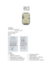
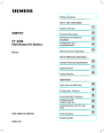
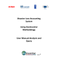
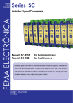
Model:A-1060
8DI,4DO Remot I/O Modules
User’s Manual
1.Description
Input::8DI (PNP/NPN), Logic Level0:+1VDC
Logic Level1:+3.5~30VDC
Output:4DO(Power Relay Output)
Power supply:10~30VDC
Diagram:
2. Features
u
RS-485 Interface
u
Wide operation temperature : -20 ~ +75 °C
u
Supports Modbus RTU / ASCII
u
Dual watchdog timer
u
LED Indicators
u
Surge , EFT and ESD protection
u
Isolation voltage: 5000 V DC
u
Free PC software “Yotta Utility”
3.Pin Assignment
Item
Pin
Description
Item
Pin
1
DI0~7 COM
Input common(+/-)
26
RL 3 NC
2
DI0
Input channel 0
25
RL 3 COM
Relay output common
3
DI1
Input channel 1
24
RL 3 NO
normally open contact
4
DI2
Input channel 2
23
RL 2 NC
normally closed contact
5
DI3
Input channel 3
22
RL 2 COM
Relay output common
6
DI4
Input channel 4
21
RL 2 NO
normally open contact
7
DI5
Input channel 5
20
NC
8
DI6
Input channel 6
19
RL 1 NC
9
DI7
Input channel 7
18
RL 1 COM
Relay output common
10
(Y)DATA+
RS-485
+
17
RL 1 NO
normally open contact
11
(G)DATA-
RS-485
-
16
RL 0 NC
normally closed contact
12
(R)+VS
+10~30VDC
15
RL 0 COM
Relay output common
13
(B)GND
GND
14
RL 0 NO
normally open contact
4. Hardware Installation
Connect an twisted-pair cable to A-1060 unit if connecting to a converter or direct to the PC(RS-485) as figure1.
Connect the power adapter to A-1060 and other apply power. Power from other device.(+10--+30VDC).
Figure 1
5.Software Configure
Install Yotta Utility.
Note: Be sure you have administrative rights &disable firewalls in windows XP.
Be sure you have connect the A-1060.
In the meantime , find the switch at the bottom of A-1060, then turn the switch to Init.
Description
normally closed contact
No Use
normally closed contact
Then open the software Yotta Utility.
Choose the COM correctly, click the search button. You can meet this page.
In the Init mode , all of the module's parameters and relative values can be set .
If you want to get the technical data in more detail ,please reference the contents of Yotta Utility.
Normal Mode
If you turn the switch to Normal , A-1060 will run normally . In this mode , A-1060's parameters and relative values cannot be
set .
Note: If you change the switch(Init/Normal) , A-1060 must be powered off and re-upelectricity . Otherwise the state
of A-1060 wouldn't change.
6. ModBus Address Mapping
Supported ModBus Code: 01/02/05/15(Reabable & writable in normal & Initial mode) R :readable W :writable
Address
Description
Normal
Init
Note(value)
00001~00008
DI0~7 Input Value
R
R
(0/1)
00017~00020
DO0~4 Output Value
R/W
R/W
(0/1)
00033~00036
DO0~4 Power On Output Value
R
R/W
(0/1)
00049~00052
DO0~4 Communication Fail Safe Value
R
R/W
(0/1)
Supported ModBus Code: 03/04/06 (Reabable & writable in normal & Initial mode) R :readable W :writable
Address
Description
Normal
Init
40065
Communication Fail Safe Time Setting Value
R
R/W
40223
Module internal temperature
R
R
40224
Module History temperature (Min) °C
R
R
40225
Module History temperature (Max) °C
R
R
Note(value)
0.0~6553.5 sec
Supported ModBus Code: 03/04/06 (Reabable & writable in normal & Initial mode) R :readable W :writable
Address
Description
Normal
Init
Note(value)
40300
Module's ID in normal mode
R
R/W
1~255
40301
Protocol in normal mode
R
R/W
0 : RTU
1 : ASCII
40302
Baud rate in normal mode
R
R/W
40303
Parity option in normal mode
R
R/W
0 : None
1 : Odd
2 : Even
40304
Stop bits in normal mode
R
R/W
0 : 1 bit
1 : 2 bit
40305
Normal Mode Time Out Setting
R
R/W
0~65535 msec