1
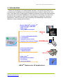
Information in this document is subject to change without notice. No part of this document may be
reproduced or transmitted in any form or by any means for any purpose without the express written
permission of HT OMEGA, Inc.
Claro halo and Claro halo XT® the HT OMEGA logo are trademarks of HT OMEGA, Inc. C-Media, the
C-Media logo and Xear 3D are trademarks of C-media Electronics Inc. Dolby, Dolby Digital, Dolby Pro
Logic IIx, Dolby Virtual Speaker and Dolby Headphone are trademarks of Dolby Laboratories. DTS
Connect, DTS Interactive and DTS: NEOPC are trademarks of Digital Theater System, Inc. DTS is a
registered trademark of Digital Theater System, Inc. EAX and A3D are trademarks of Creative
Technology Ltd. Microsoft, DirectSound3D, Microsoft Windows are trademarks of Microsoft Corporation.
Other company and product names may be trademarks of the respective companies with which they
are associated.
Dolby Digital RTCE driver is manufactured under license from Dolby Laboratories.
Manufactured under license from DTS, Inc. U.S. Pat. No's. 5,451,942; 5,956,674; 5,974,380;
5,978,762; 6,487,535 and other U.S. and world-wide patents issued and pending. DTS CONNECT,
DTS INTERACTIVE and DTS NEO:PC are trademarks of DTS, Inc. DTS is a registered trademark of
DTS, Inc. Copyright 1996, 2002-2005 Digital Theater Systems, Inc. All Rights Reserved.
ASIO is a trademark and software of Steinberg Media Technologies GmbH.
© 2008 HT OMEGA, Inc.
The product described in this manual has been developed and produced by HT OMEGA, Inc. The
information furnished in this document is provided for the customers’ reference. However, HT OMEGA,
Inc. assumes no liability for any incidental, consequential and certain other damages that arise out of or
relating in any way to the software or hardware device.
HT OMEGA.Inc.
1912 Augusta Ct. Ontario, CA 91761 USA.
Webservice: http://www.htomega.com
HTO Claro halo User Manual Rev. 1.1
Table of Contents
1. Instruction ................................................................. 4
2. Features Overview ..................................................... 5
3. Installing H/W, S/W, and Speakers ........................... 6
3.1 Claro halo Hardware .................................................................................................... 6
3.2 Connection and Speaker Setup ................................................................................... 14
3.3 Claro halo Software .................................................................................................... 16
4. Using Audio Driver ....................................................18
4.1 Claro halo Software Control Panel............................................................................. 18
4.2 Main Setting ............................................................................................................... 19
4.3 Mixer/Volume............................................................................................................. 28
4.4 Sound Effects ............................................................................................................. 31
4.5 Magic VoiceTM and Karaoke ...................................................................................... 32
4.6 FlexBassTM ................................................................................................................. 33
4.7 Look for Information .................................................................................................. 34
5. FAQ & Troubleshooting .............................................35
6. Support / Contact .....................................................37
Copyright © 2008, HT OMEGA, Inc. All Right Reserved.
http://www.htomega.com
2
HTO Claro halo User Manual Rev. 1.1
1. Introduction
Thanks for choosing an HT OMEGA audio solution! This manual will guide you in
configuring the Advanced Driver Software Architecture (ADSATM) used by the Claro
halo. Claro halo’s built-in high fidelity headphone amplifier achieves the best listening
quality with the most stereo headphone. And Xear 3DTM technology, the Claro halo
provides a value-added PC audio solution with maximum support for all kinds of
applications. With this manual, users can quickly take advantage of these great
features to enjoy amazing sound quality.
- Support EAX2.0TM and A3D1.0TM
- Support DS3DTM H/W &S/W
- Magic VoiceTM
- Sensaura® CPL3D engine
Games
s
-
7.1 Virtual SPEAKER SHIFTER
5.1 Xearphone
2-Speaker Virtual Theater
Earphone Plus Personal Theater
-
Environment Emulation
Environment Sizes
10-Band Equalizer
DVD Movies
music
(MP3/CD)
-
Magic VoiceTM
Microphone Echo Effect
Key-Shifting
Vocal Cancellation
ADSATM Features for All Applications
Copyright © 2008, HT OMEGA, Inc. All Right Reserved.
http://www.htomega.com
3
M
e
s
s
e
n
g
e
r
/
K
a
r
a
o
k
e
HTO Claro halo User Manual Rev. 1.1
What’s in the box?
You should have received the following with your Claro halo:
l
l
l
l
l
l
l
l
Claro halo soundcard
Claro halo XT (Optional)
Drivers/Applications CD
Fiber Optical Digital Cable
RCA cable
RCA to Stereo convertor.
Headphone extension cable
This manual
Specifications
(1) Sound Processor
l C-Media CMI8788/PCI-8ch PCI Chipset
l Integrated S/PDIF Output supports 44.1kHz/48kHz/96kHz/192kHz sample
rate and 16/24-bits resolution
l 24-bit/192kHz Stereo ADC
l Full-duplex ultra high 2CH 24-bit/192kHz DAC
(2) Interface
l PCI Rev. 2.2 compliant with 32bit PCI bus mastering modes
l Independent high performance headphone amplifier for headphone output.
l Jumpers switch to select different impedance level of headphones. .
l Enhanced design on microphone input level circuit.
l High quality RCA connector for Front Output.
l Onboard Optical transmitter and receiver for Optical Digital Output and Input
l Onboard S/PDIF Input, Output connectors: Coaxial or CD_S/PDIF Input and 2
pin digital output connector
l Front Panel Audio supports: 10pin connector (Intel AC97 Front Panel Audio
Compliant) for Front Panel Audio of PC case. With the front panel audio
enabled, users can connect a second microphone without any reduction of
input signal level.
Copyright © 2008, HT OMEGA, Inc. All Right Reserved.
http://www.htomega.com
4
HTO Claro halo User Manual Rev. 1.1
2. Features Overview
The following is an overview of the features of the Claro halo. The Claro halo drivers
support recent generation multi-channel digital functions and the following key
features:
l C-Media Xear 3D™ 7.1 Virtual Speaker Shifter technology with Claro halo
XT® (Optional).
l C-Media FlexBass™ – configurable LFE channel crossover frequency (from
50 to 250Hz)
l C-Media Magic Voice™, a popular feature for disguising voice in online
chatting
l C-Media’s unique Karaoke functions: Microphone Echo, Key-shifting,
10-band EQ for every channel, 27 global reverberation environments, Play3D
demo program
l Supports most industrial standards of 3D sound for PC gaming, including
EAX™1.0&2.0, A3D™ 1.0, OpenAL and DirectSound™
l Support 7.1 CH audio playback for Win XP(Microsoft® DirectX V.9.0 and
above is required) with Claro halo XT® (Optional).
System Requirements (Minimum)
l Genuine Intel® Pentium® III 800 MHz or equivalent AMD® processor
l 256 MB RAM
l Microsoft® Windows® XP Service Pack 1 (SP1)
l Available 2.1 compliant or higher PCI slot for the audio card
l If you install XT® (optional), another mounting slot for XT®
l Headphones or 2channel amplified speakers (available separately)
l 500 MB of free hard disk space
l CD-ROM or DVD-ROM drive required for software installation from CD
Copyright © 2008, HT OMEGA, Inc. All Right Reserved.
http://www.htomega.com
5
HTO Claro halo User Manual Rev. 1.1
3. Installing H/W, S/W, and Speakers
3.1 Claro halo Hardware
(1) Connectors
① MIC IN (3.5mm Stereo-jack): Connects to external condenser or dynamic
microphone for voice input. Special OPAMP controlled preamp circuits on board
provide increased MIC input gain.
② LINE IN (3.5mm Stereo-jack): Connects to external analog line-level sources,
such as CD players, MP3 players, MD players, TV card's internal line output and
other analog stereo output devices.
③ Headphone (3.5mm Stereo-jack): Connects to Headphone inputs. This output
is linked to Front channel..
④ FRONT L (RCA jack): Connects to Front Left inputs on powered analog
speakers or an external amplifier.
Copyright © 2008, HT OMEGA, Inc. All Right Reserved.
http://www.htomega.com
6
HTO Claro halo User Manual Rev. 1.1
⑤ FRONT R (RCA jack): Connects to Front Right inputs on powered analog
speakers or an external amplifier.
⑥ OPTICAL INPUT (S/PDIF OPTICAL Digital Input connector): Connection for
external digital devices such as a CD or DVD player. PCM digital audio can be
monitored on sound card analog outputs.
Note: Dolby® Digital, DTS® stream, and other Non-PCM digital audio sources
from external digital device such as DVD player, PS3 or XBOX can be
passed-through to digital output connectors only. These signals can’t be
monitored on analog output.
⑦ OPTICAL OUTPUT (S/PDIF OPTICAL Digital Output connector): Connects to
external digital devices like AV receivers, decoders or digital speaker systems.
High quality Optical S/PDIF output transmits PCM digital audio. Also allows
pass-through of Non-PCM signal like Dolby® Digital and DTS® stream to
external DD/DTS decoder and A/V receivers.
⑧ CD_IN (4Pin MPC2): Connects to the CD analog audio output on an internally
mounted CD/DVD drive using an analog CD audio cable. (4pin MPC2 to 4pin
MPC2 CD Audio Cable, available separately)
Pin 1 - Left (white cable)
Pin 2 - Ground (black cable)
Pin 3 - Ground (black cable)
Pin 4 - Right (red cable
⑨ AUX_IN (4Pin MPC2): Connects to the internal analog audio output such as TV
card. (4pin MPC2 to 4pin MPC2 CD Audio Cable, available separately)
Pin 1 - Left (white cable)
Pin 2 - Ground (black cable)
Pin 3 - Ground (black cable)
Pin 4 - Right (red cable)
Copyright © 2008, HT OMEGA, Inc. All Right Reserved.
http://www.htomega.com
7
HTO Claro halo User Manual Rev. 1.1
⑩ CD S/PDIF or Coaxial digital input (2Pin digital IN): Connects to CD-ROM
drive Digital Output or external digital device output with using a CD S/PDIF
cable (2pin-2pin S/PDIF digital cable) or 2pin-RCA cable
Note: This 2pin-RCA cable is available at http://www.htomeg.com
⑪ Coaxial or CD S/PDIF Output (2Pin digital out): Connects to external digital
input device such as digital receiver with using Spin-2pin or 2pin-RCA cable. .
(2) Headers/Connectors on board
Copyright © 2008, HT OMEGA, Inc. All Right Reserved.
http://www.htomega.com
8
HTO Claro halo User Manual Rev. 1.1
① XT Connector: Connect to XT (optional) for multi-channel analog outputs.
Please note prominence and depression. Do not connect the other way.
② MIDI_IO (MIDI Port Bracket 16Pin Header) : Connects to the MIDI port for MIDI
device such as master keyboard and synthesizer.
MIDI connector is available at http://www.htomega.com.
③ Front Panel Audio (10 Pin Header): Connects to the Front Panel Audio Cable of
your PC case.
Pin 1 - MIC
Pin 2 - Ground
Pin 3 - Bias (MIC Power)
Pin 5 - Front Right
Pin 9 - Front Left
Pin 4,6,7,8 and10 are not available
Note: When user connects headphones to the Front Panel Audio, entire analog
outputs will be muted automatically. And you can disable this feature by using the
front headphone detect jumper.
Note: This muting feature is for only front panel audio. The headphone output of
sound card doesn’t provide mute feature.
Copyright © 2008, HT OMEGA, Inc. All Right Reserved.
http://www.htomega.com
9
HTO Claro halo User Manual Rev. 1.1
④ Front Panel detection: When Front Panel Audio Headphone jack is inserted, all
speakers will be muted. If you need to disable this feature, change jumper as
below.
Turn on detection (mute able)
Turn off detection (mute disabled)
⑤ Headphone impedance jumper :
Claro halo is designed to accommodate high impedance headphones up to 600ohm
Factory default is low setting. Please set to high for the headphones over 32ohm..
Note: We recommend not to use low impedance headphone with high setting.
(3) Swappable OP amp connector for Claro halo.
Claro halo provides 4 pcs swappable dual opamp for Front Channel output and
Headphone output.
Copyright © 2008, HT OMEGA, Inc. All Right Reserved.
http://www.htomega.com
10
HTO Claro halo User Manual Rev. 1.1
1 (U8) – Left channel input from DAC. (+/- signal separately) ,
2 (U9) – Left channel output to Headphone and RCA
3 (U10) – Right channel input from DAC (+/-signal separately)
4 (U11) – Right channel output to Headphone and RCA
Note: When you change OPAMP, please note #1 pin location as below.
The circle shows #1 pin.
(4) Claro halo PCI installation.
Insert Claro halo card to empty PCI slot.
Tighten RCA jacks with included lock washer and nut.
Copyright © 2008, HT OMEGA, Inc. All Right Reserved.
http://www.htomega.com
11
HTO Claro halo User Manual Rev. 1.1
(5) XT® (Optional)
If you need to extend analog output from 2ch to 8 ch, you have to install XT.
XT®
① SIDE SURROUND L (RCA jack): Connects to Rear Left inputs on amplifier or
powered multi-channel analog speakers.
② SIDE SURROUND R (RCA jack): Connects to Rear Right inputs on amplifier or
powered multi-channel analog speakers.
③ CENTER (RCA jack): Connects to Center inputs on amplifier or powered
multi-channel analog speakers.
④ S.WOOFER (RCA-jack): Connects to Sub-Woofer inputs on amplifier or
powered multi-channel analog speakers.
⑤ BACK SOURROUND L (RCA-jack): Connects rear surround Left input on
powered multi-channel analog speakers, an external multi-channel amplifier in
7.1 channel analog playback modes.
⑥ BACK SOURROUND R (RCA-jack): Connects rear surround Right input on
powered multi-channel analog speakers, an external multi-channel amplifier in
7.1 channel analog playback modes.
⑦ Extension Cable connector: Connect to Claro halo card with 20pin cable.
Copyright © 2008, HT OMEGA, Inc. All Right Reserved.
http://www.htomega.com
12
HTO Claro halo User Manual Rev. 1.1
(6) XT® installation.
1. Link connector with 20pin data cable.
2. Insert XT® card to empty slot of computer case.
(7) Swappable OP amp for XT
XT provides 3 pcs swappable dual opamp for rear L/R , center/subwwofer and side
L/R analog output.
(1) Rear L/R OPAMP
(2) CENTER/SUB WOOFER OPAMP
(3) SIDE L/R OPAMP
Copyright © 2008, HT OMEGA, Inc. All Right Reserved.
http://www.htomega.com
13
HTO Claro halo User Manual Rev. 1.1
3.2 Connection and Speaker Setup
(1) Connection
① Connecting 2 Channel Speakers
② Connecting Headphone
Note: Do not connect headphone output of Sound Card to Front speaker
input connector.
③ Connecting Microphone and External Analog Devices
Copyright © 2008, HT OMEGA, Inc. All Right Reserved.
http://www.htomega.com
14
HTO Claro halo User Manual Rev. 1.1
④ Connecting External Digital Devices, decoder or digital AV receiver.
⑤ Connecting analog 4ch, 5.1ch or 7.1 ch Speakers (XT user Only)
Copyright © 2008, HT OMEGA, Inc. All Right Reserved.
http://www.htomega.com
15
HTO Claro halo User Manual Rev. 1.1
3.3 Claro halo Software
Please disable any existing PCI or onboard sound/audio devices (may need to
disable in BIOS) and remove the associated software and drivers before
installing "Claro halo" to avoid potential device and/or driver conflicts. Drivers
and applications can be removed through the “Add or Remove Programs” menu in
Windows Control Panel.
(1) Installing the drivers and software
① Turn on PC. Windows will automatically detect new hardware-Multimedia
Audio Controller and prompt the Found New Hardware Wizard. Click the Cancel
button to end this process.
② Insert installation CD into the CD/DVD drive. Installation CD will launch
automatically only if the Auto-Insert Notification option is enabled for your CD/DVD
drive. If the installation menu does not appear after inserting the installation CD into
your CD/DVD drive, browse to the drive letter that contains the installation CD and
double-click on the CD/DVD drive icon to explore it. Search for and run
"SETUP.EXE" and proceed to the next step.
③ When the installation menu appears, select "Next". Follow the instructions that
appear during the installation selecting the options that best match your audio setup.
Copyright © 2008, HT OMEGA, Inc. All Right Reserved.
http://www.htomega.com
16
HTO Claro halo User Manual Rev. 1.1
④ When prompted, reboot the system. Wait a few minutes for the installation to
complete. The wait time will vary depending on the speed of your PC. Please wait
for the system to reboot to properly complete the installation.
(4) TO UNINSTALL "Claro halo" drivers and softwares
① Open the Windows Control Panel (Start => Settings => Control Panel).
② Open the Add/Remove Programs applet. Select "HT OMEGA Claro" and click
on the "Change/Remove" button to the lower right of the screen.
③ To complete the uninstall process, Windows needs to be restarted. Select Yes, I
want restart my computer now then press Finish. (Please do not skip restart
now before installing updated driver )
Copyright © 2008, HT OMEGA, Inc. All Right Reserved.
http://www.htomega.com
17
HTO Claro halo User Manual Rev. 1.1
4. Using Audio Driver
4.1 Claro halo Software Control Panel
This is C-Media’s 3D audio control panel that allows the user to manage all audio
configurations. After finishing the installation of the driver and rebooting the system,
the audio control panel will be available through two locations:
1.Left-Click the icon in the system tray in the right-bottom of your screen. You can also
click right button the icon to access the audio-related menu.
2. Double-click “HT OMEGA Claro” icon in Windows “Control Panel”.
(Start=>Setting=>Control Panel)
Main Control Program icon on Control Panel
3. In case of 64bit os, you can find Control Program Icon on View32-bit Control Panel
Items in Control Panel.
`
Copyright © 2008, HT OMEGA, Inc. All Right Reserved.
http://www.htomega.com
18
HTO Claro halo User Manual Rev. 1.1
4.2 Main Setting
There are 6 separated parts on main setting.
1. Analog output mode select
2. S/PDIF output mode select
3. Audio System Status
4. DSP Mode On/Off switch button.
5. DSP technologies select buttons
6. Figure of “Speaker test mode” and “DSP mode”
4
1
5
2
3
6
Claro halo Main Setting
Copyright © 2008, HT OMEGA, Inc. All Right Reserved.
http://www.htomega.com
19
HTO Claro halo User Manual Rev. 1.1
(1) Analog Output select mode
This part can let user to select analog and digital output mode. There are 5 kinds of
analog output mode: Earphone Output Mode, 2 / 4 / 5.1 / 7.1 Channel Output
Mode.
NOTE: Claro halo supports Earphone and 2ch analog output. Claro halo with XT user
can extend 4, 5.1, 7,1 channel analog output
(2) Digital Output select mode
Digital output mode is configured to define which format will be out by S/PDIF
interface. There are totally 7 kinds of digital output mode: Dolby Digital Live/ DTS
Interactive/ Digital audio 44.1K/ 48K/ 96K/ 192K/ SPDIF In Loopback.
S/PDIF Output Select mode
l
Dolby Digital Live--- Audio data will be encoded to AC-3 5.1 format and output
via S/PDIF out
l
DTS Interactive--- Audio data will be encoded to DTS cinema 5.1 bit stream
format and output via S/PDIF out
l
l
l
l
l
Digtal Audio 44.1 KHz---S/PDIF out with 44.1KHz sample rate
Digtal Audio 48 KHz---S/PDIF out with 48KHz sample rate
Digtal Audio 96 KHz---S/PDIF out with 96KHz sample rate
Digtal Audio 192 KHz---S/PDIF out with 192KHz sample rate
S/PDIF In Loopback----S/PDIF input signal loop back to S/PDIF out
NOTE: When Dolby Digital Live or DTS Interactive is enabled the analog outputs
will be turned off automatically to prevent interference.
Copyright © 2008, HT OMEGA, Inc. All Right Reserved.
http://www.htomega.com
20
HTO Claro halo User Manual Rev. 1.1
(3) Audio System status
2
1
3
. Audio System Status
1. Output Mode Status:. There are 5 kinds of output mode: Earphone Output Mode,
2 / 4 / 5.1 / 7.1 Channel Output Mode.
2. Spectrum:
10-band spectrum of real-time audio playback on the system is shown here.
3. Digital I/O Status:
: Digital Output Status –
(1) For DTS Interactive output: dts logo is shown here.
(2) For Dolby Digital Live! output: AC3 is shown here.
(3) For stereo PCM output: sampling rate is shown here.
: Digital Input Status For stereo PCM input: sampling rate is shown here.
(4) DSP Mode
This button can let you switch DSP vision function on or off. When you turn it on, you
can see the DSP working vision. When you turn it off, you will see standard speaker
test mode.
There are totally 5 kinds of DSP mode you can select here. C-Media 7.1 Virtual
Speaker Shifter / Dolby ProLogic IIx / Dolby Headphone (only exist when
Headphone on speaker mode setup) / Dolby Virtual Speaker (only exist when 2CH
on speaker mode)/ DTS NEO:PC (exclusive with Dolby ProLogic IIx).
Copyright © 2008, HT OMEGA, Inc. All Right Reserved.
http://www.htomega.com
21
HTO Claro halo User Manual Rev. 1.1
C-Media 7.1Virtual
Dolby ProLogic IIx
Dolby Headphone
Dolby Virtual Speaker
DTS NEO:PC
Speaker shifter
(5) Figure of Speaker Test and DSP Mode
1. Speaker test mode (This feature provides under XP only)
Speaker Tester is used to help users to place the speakers at the correct position.
1
2
3
4
5
7
6
Speaker Test
1. Digital Gain: When enabled, the digital gain of digital audio source can be adjusted
individually for each channel.
2. Speaker Time Delay: It only exist when the speaker mode is upon 4CH.
·
·
Turn On Speaker Time Delay :
Set channel delay time :
Copyright © 2008, HT OMEGA, Inc. All Right Reserved.
http://www.htomega.com
22
HTO Claro halo User Manual Rev. 1.1
This function is a professional audio feature to set your multi-channel speaker output
delay time. It must be used for all modes in Dolby Pro Logic II and Dolby Digital. With
this feature, you can set your Center / Side Surround / Back Surround channels
delay time as your professional audio perform request.
3. Speaker Test: Click the speaker icon on the screen, the system will play a sound
and send it to designated speaker.
4. Speakers Tester Scenario: The scenario will change according to the output mode
of the audio system.
Earphone
2CH
4CH
5.1CH
7.1CH
Speaker Channel Test
5. The diagram of digital output: It will be visible if digital output is enabled.
Digital output is enabled
Digital output is disabled
Digital Output
6. Auto Play: It will play sound automatically while circling all speakers on the screen
7. Stop Auto Play: It will stop auto play function.
2. DSP mode
Audio DSP setting let user to adjust the setting of corresponding DSP. The DSP can
be divided into categories: Input Processor for stereo audio source and Output
Copyright © 2008, HT OMEGA, Inc. All Right Reserved.
http://www.htomega.com
23
HTO Claro halo User Manual Rev. 1.1
Processor.
1. Dolby feature process in C-Media driver:
DOLBY FEATURE PROCESS
A.
Input Processor: Dolby Pro Logic IIx or Direct Copy Mode.
B.
Output Processor: C-Media SPEAKER SHIFTER, Dolby Headphone for
earphone output mode, Dolby Virtual Speaker for 2CH output mode, and Dolby
Digital Live! for Digital Output.
2. DTS feature process in C-Media driver:
The C-Media Oxygen HD driver allows a range of different processing options for
stereo/ 5.1/ 7.1 channel audio.
DTS FEATURE PROCESS
A. Input stage: DTS NEO:PC or Multi-channel Stereo
B. Output stage: C-Media Speaker shifter, DTS Interactive for digital output
Copyright © 2008, HT OMEGA, Inc. All Right Reserved.
http://www.htomega.com
24
HTO Claro halo User Manual Rev. 1.1
3. Dolby Pro Logic IIx Mode
1
2
3
4
5
Dolby Pro Logic IIx
1 Center Width Control
○
2 Reset balance button
○
3 Dimension Control
○
4 Music mode / Cinema mode select, 1 and 2 only can be adjusted under Music
○
mode
5 Panorama Control, this is tested by measuring the output levels of the Left /
○
Right surround channel when turned on and off
4.
Dolby Headphone Mode
2
3
1
Dolby Headphone
1 Reference Room Emulation
○
2 Livelier Room Emulation
○
3 Larger Room Emulation
○
Copyright © 2008, HT OMEGA, Inc. All Right Reserved.
http://www.htomega.com
25
HTO Claro halo User Manual Rev. 1.1
5. Dolby Virtual Speaker
1
2
Dolby Virtual Speaker
1 Reference Room Mode
○
2 Wide Mode
○
6. DTS NEO:PC
2
1
3
4
1
○
2
○
3
○
4
○
DTS NEO:PC
10 degrees Center Width Control
Reset balance button
Dimension Control
Music mode / Cinema mode select, 1 and 2 only can be adjusted under Music
mode
Copyright © 2008, HT OMEGA, Inc. All Right Reserved.
http://www.htomega.com
26
HTO Claro halo User Manual Rev. 1.1
7. C-Media SPEAKER SHIFTER
5
1
2
3
4
6
7
8
SPEAKER SHIFTER
1 Volume Control: Increase / decrease the volume of all channels by 1 dB.
○
2 Auto Rotation Mode: The virtual speakers will rotate clockwise or
○
counterclockwise slowly. For example, if clockwise is selected:
à
T=0
à
T=0.25 sec
T= 1 sec
3 Manually Rotation Mode: Use mouse to rotate the virtual speakers on the
○
screen manually.
4 Free Moving Mode: Use pointer and click-and-drag to move the location of
○
individual virtual speakers / virtual listener.
5 Reset: Reset the location of virtual speakers / virtual listener to default.
○
6 Virtual Speaker: Each virtual speaker virtualizes one channel of the 7.1
○
channel speakers in the real world.
7 Virtual Listener: The virtual listener virtualizes your position in the real world.
○
8 Volume indicator for each channel.
○
Copyright © 2008, HT OMEGA, Inc. All Right Reserved.
http://www.htomega.com
27
HTO Claro halo User Manual Rev. 1.1
4.3 Mixer/Volume
2
3
1
5
4
6
7
8
10
0
9
Main Mixer
1. Audio System Status: Here showed the output channel mode of the system.
2. Panning of Master Volume: It’s used to adjust the balance of left / right channel
globally.
3. Volume Control of Digital Audio Source: It’s used to adjust the volume of each
digital audio source on the system.
4. Volume Indication Meter of Playback: It will display the playback volume in
real-time.
5. Mute / Un-mute Button: The digital audio source is un-muted if button is lighted.
Copyright © 2008, HT OMEGA, Inc. All Right Reserved.
http://www.htomega.com
28
HTO Claro halo User Manual Rev. 1.1
6. Graph of Selected Recording Device: The graph stands for recording device
selected.
7. Volume Indication Meter of Recording: It will display the recording volume in
real-time.
8. Recording Source Selection: Only one recording source is allowed to be selected
at one time.
9. Monitoring : Monitoring of recording source is enabled here
10. Advanced Setting: There are two advanced setting options for Microphone and
S/PDIF input
(1) Microphone Setting
1
2
Microphone Advanced Settings
① Microphone Boost: If you feel that the mic volume is too low there is an
option to boost +20dB. Check the “Boost” box to enable it. Keep in mind that
background noise will also increase.
NOTE: The Claro halo uses a sensitive microphone preamp. To avoid damage to
your speakers, do not use maximum volume level when plugging in a
microphone. We recommend that volume be set at half or less. Volume level
can be safely adjusted once the microphone has been connected.
② Monitoring: You can hear microphone input on your speaker.
Copyright © 2008, HT OMEGA, Inc. All Right Reserved.
http://www.htomega.com
29
HTO Claro halo User Manual Rev. 1.1
(2) S/PDIF Input Advanced Setting
1
2
3
S/PDIF In Advanced Settings
S/PDIF-IN Setting
① “Validity Check” will assure to neglect the non-PCM audio to avoid the noise. It
requires that the input data follow the specification of IEC60958.
② Select the connection type: Optical (S/PDIF-IN #1) or Coaxial (S/PDIF-IN #2).
③ When you are recording S/PDIF-In audio, you can choose to monitor it using
analog speakers.
Note: We recommend stopping monitoring function during usual playback.
Note: Claro halo doesn’t provide AC3 signal decoding such as Dolby Digital or dts.
For licensing and copyright protection purposes, soundcard manufacturers
are effectively prevented from adding DD/DTS decoders to their products.
The reasoning is that the only legal use of DD/DTS decoders is for playback
of licensed soundtracks from DVD movies. So please set to PCM 2ch on
your external digital devices such as PS3 or XBOX360.
Note: If you use external receiver such as Z-5500 speaker, S/PDIF input signal can
be pass-thru to receiver. In this case, you can use Dolby Digital or dts setting
on your external digital devices such as PS3 or XBOX360.
Copyright © 2008, HT OMEGA, Inc. All Right Reserved.
http://www.htomega.com
30
HTO Claro halo User Manual Rev. 1.1
4.4 Sound Effects
(1) Environment Emulation
1: Select an “Environment” effect to emulate multiple environments.
2: “Environment Size” can be adjusted from large to small (default setting is
medium). Changing the size will alter the virtual space in which the sound is
reproduced.
(2) 10-Band Equalizer
3: There are 12 preset modes such as Bass, Treble, Live, Rock, Jazz, etc.
4: Custom equalizer settings can be saved. Enter a name into the blank space and
click “+” to add your personal setting into the “User Defined” list. Click “-“ to delete
the currently selected user defined setting from the list.
1
3
2
4
Effect Setting
Copyright © 2008, HT OMEGA, Inc. All Right Reserved.
http://www.htomega.com
31
HTO Claro halo User Manual Rev. 1.1
4.5 Magic VoiceTM and Karaoke
1: Click “On” to turn on the Karaoke function (button should be blue).
NOTE: First time you turn on Magic Voice, the driver will default select the
microphone input as the recording source. Click “OK” to close this window.
2: Reset whole settings to default value.
3: “Microphone Echo” will add an echo effect. The volume and amount of echo can
be adjusted according to user’s preference. Magic VoiceTM is a special effects tool
that will change the sound of your voice. To use it, select Magic Voice from the
pull-down menu and choose one of the five effects buttons. The special effects can be
used when talking to other people over the network, such as messenger applications,
VOIP and online games. Because these two features require real-time microphone
recording, you should suspend other recording applications while using Microphone
Echo or Magic Voice.
4: You can enable Key-Shifting for the Karaoke VCD or the music to suit your voice
pitch. The range is adjustable from -4b to +4#.
5: If the music source includes the original vocals, you may try the “Vocal
Cancellation” function to cancel it (0~100). The success of the effect depends on the
recording method used to create the audio source. Karaoke VCD or CD, typically do
not include vocals and should not require “Vocal Cancellation.”
1
2
3
4
5
Karaoke/ Magic Voice Setting
Copyright © 2008, HT OMEGA, Inc. All Right Reserved.
http://www.htomega.com
32
HTO Claro halo User Manual Rev. 1.1
4.6 FlexBassTM
“FlexBass” is a driver feature to realize Bass Management technology. Bass
Management is also a necessary feature for Dolby Digital technology. A bass
management feature can help you to manage the low-frequency content of your
sound. In generally, humans cannot tell which direction frequencies below 100 Hz
come from. If speaker cannot output low frequencies, it is better to send them to
another speaker such as a subwoofer, or the full range speaker (Large Speaker).
1
3
2
5
4
FlexBass Setting
1. FlexBass On/Off switch button. Turn on to start FlexBass function.
2. Crossover frequency adjustment. To define what numbers Hz below as
low-frequency signal. Range from 50-250 Hz.
3. Frequency Meter. It records what frequency number you adjust is.
4. Large/Small speaker select. Every channel is default as a small speaker to be
extracting their low frequency content to the subwoofer out. When you choice
someone to be a large speaker, its low frequency will not be extract away and
perform by itself.
5. Speaker configuration status. To see the speaker setting by picture.
Copyright © 2008, HT OMEGA, Inc. All Right Reserved.
http://www.htomega.com
33
HTO Claro halo User Manual Rev. 1.1
4.7 Look for Information
The Information tab displays details about the Claro halo’s audio-related properties
including the audio chip, driver version, 3D Audio Engine and Microsoft DirectX
Version. The Audio Configuration icon can be shown in the system tray by
checking the box.
Driver Information
Copyright © 2008, HT OMEGA, Inc. All Right Reserved.
http://www.htomega.com
34
HTO Claro halo User Manual Rev. 1.1
5. FAQ & Troubleshooting
Q1: Multi-Channel Output in VISTA
In VISTA, the System Input is different from XP driver. XP provides DirectX for multiple
audio outputs but VISTA doesn't. C-media provides System Input for this feature. User must
select System Input channel depending on sound source.
If you play 2ch stereo files such as MP3, AVI and games then set to 2ch for System Input no
matter what type of multi-channels speaker system you have and if you play multi-channel
data such as DVD title, then please set to 6ch in System Input.
Example1.
When you play game or 2ch data in 5.1ch analog speaker system.
In this case, please set to 2ch on System Input and Set to 6ch on Analog Output.
Copyright © 2008, HT OMEGA, Inc. All Right Reserved.
http://www.htomega.com
35
HTO Claro halo User Manual Rev. 1.1
Q2:What is a 7.1CH listening environment and how it is different
from 5.1CH.
1. The 7.1 channel mode is the latest multi-channel audio format and
technology on the market. It includes center, subwoofer, front left, front right,
left surround, right surround, left back surround, and right back surround
according to Dolby Digital and DTS ES standards.
2. The 7.1CH content is referred to as Dolby Digital EX by Dolby Lab and
DTS-ES (Extended Surround) by DTS.
3. The difference between 5.1CH and 7.1CH is the addition of 2CH. The two
extra speakers were placed in the rear side(s) to enhance the immersive
experience of surround sound.
5.1CH Environment
7.1CH Environment
Copyright © 2008, HT OMEGA, Inc. All Right Reserved.
http://www.htomega.com
36
HTO Claro halo User Manual Rev. 1.1
6. Support / Contact
HT OMEGA offers various resources to provide customer support. Please visit our
website http://www.htomega.com to access our customer service section. The latest
FAQ’s, drivers, product documentation and applications can be found on the website,
along with any new product development and information.
Thank you for choosing an HT OMEGA product. We look forward to providing you with
the highest quality products and service.
Copyright © 2008, HT OMEGA, Inc. All Right Reserved.
http://www.htomega.com
37
HTO Claro halo User Manual Rev. 1.1
NOTE: This equipment has been tested and found to
comply with the limits for a Class B digital device,
pursuant to part 15 of the FCC Rules. These limits are
designed to provide reasonable protection against
harmful interference in a residential installation.
This equipment generates, uses and can radiate radio
frequency energy and, if not installed and used in
accordance with the manufacturer’s instructions, may cause harmful interference to
radio communications. However, there is no guarantee that interference will not
occur in a particular installation. If this equipment does cause harmful interference
to radio or television reception, which can be determined by turning the equipment
off and on, the user is encouraged to try to correct the interference by one or more
of the following measures:
-Reorient or relocate the receiving antenna.
-Increase the separation between the equipment and receiver.
-Connect the equipment into an outlet on a circuit different from that to which the
receiver is connected.
-Consult the dealer or an experienced radio/TV technician for help.
CAUTION : Changes or modifications not expressly approved by the manufacturer
responsible for compliance could void the user’s authority to operate the equipment.
Copyright © 2008, HT OMEGA, Inc. All Right Reserved.
http://www.htomega.com
38
HTO Claro halo User Manual Rev. 1.1
LIMITED WARRANTY
HT OMEGA, Inc. warrants to the original purchaser only that the hardware product will be free of
defects in materials and workmanship for a period of twelve (12) months from the date of purchase. HT
OMEGA, Inc. will, at its sole discretion, repair or replace the product if it is found to be defective. This
warranty does not cover a product failure that is the result of misuse, abuse, modification,
misapplication, or normal wear and tear. No claim is made for merchantability or fitness for any purpose.
In no event will HT OMEGA, Inc. be liable for any direct, indirect, consequential, or incidental damages
arising out of the use of this product. In no event will HT OMEGA’s liability exceed the purchase price
you paid for the product.
The purchaser must contact HT OMEGA, Inc or its regional representative to receive prior approval
before returning a faulty unit. All such returns must be shipped to HT OMEGA, Inc in the original
packaging including all accessories (documents, cables, software, etc.) along with the original sales
receipt. Any costs associated with the return/shipping/insuring the package are the sole responsibility of
the end-user. Shipments without freight prepaid will not be accepted. If the returned product is deemed
to be defective, the repaired or replacement product will be returned at no extra charge via the carrier
chosen by HT OMEGA, Inc.
Copyright © 2008, HT OMEGA, Inc. All Right Reserved.
http://www.htomega.com
39