1
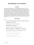
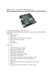
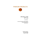
Prado Board by Silica Architech
Documentation
Release 1.0
Silica
February 14, 2014
Contents
i
ii
Prado Board by Silica Architech Documentation, Release 1.0
Version 1.0.0
Copyright (C)2013 Silica an Avnet company
Contents
1
Prado Board by Silica Architech Documentation, Release 1.0
2
Contents
Prado Board by Silica Architech Documentation, Release 1.0
The daughterboard Architech Prado of Silica helps to access the WiFly RN-131C module (version 4.00) of
Microchip.
It was designed to be connected to the LPC1115 LPCXpresso board.
The project provides a demo developed with the LPCXpresso IDE and through the microcontroller LPC1115
configures the RN-131C module to operate in different modes.
Architech Prado Features:
• Interfaceable with:
– LPC1115 LPCXpresso board
– mBed board
• 1 UART 3,3V level for debugging purpose
• 5 status leds
• Power supply by mini-usb
The WiFly radio module is a complete standalone embedded wireless LAN access device.
The device has on board TCP/IP stack and applications, requiring only 4 pins (POWER, TX, RX, GND) to design in.
Once initial configuration is set, the radio can automatically access the Wi-Fi network and send/receive serial data
over UART.
For a quick consultation of the instruments used, please visit the following websites:
• IDE LPCXPRESSO (free IDE up to 128KB):
– http://lpcxpresso.code-red-tech.com/LPCXpresso/
• LPC1115 LPCXpresso:
– http://www.embeddedartists.com/products/lpcxpresso/lpc1115_xpr.php
– http://www.nxp.com/techzones/microcontrollers-techzone/tools-ecosystem/lpcxpresso.html
– http://www.nxp.com/products/microcontrollers/cortex_m0_m0/LPC1115FBD48.html
• Connected to the Prado daughterboard:
Contents
3
Prado Board by Silica Architech Documentation, Release 1.0
• Microchip RN-131C:
– http://www.microchip.com/wwwproducts/Devices.aspx?dDocName=en558369
• The demo has been developed starting from the design LPCOpen platform v1.03
– http://www.lpcware.com/content/nxpfile/lpcopen-platform
and with the demo of the microchip “RN171 and RN131 PICtail WebServer” ver 1.0R:
• http://www.microchip.com/stellent/idcplg?IdcService=SS_GET_PAGE&nodeId=1406&dDocName=en560211
We suggest you to read the Quick Start Guide to setup your evaluation system
Quick start guide
This guide explains how to use this application and provides an overview of on the structure of the project firmware
4
Contents
CHAPTER 1
Pass-Through Mode
Warning: For using this mode you need a UART interface (3,3V level only) to connect Prado to your pc. This
interface is not provided.
The demo provided can operate in pass-through mode. Enable this mode to be able to send and receive commands
to the console manually through terminal WiFly module. In order to enable this mode follow the following steps:
1. Insert the jumper connector J1
2. Connect to CN1 (UART 3,3V level only) a UART interface (not provided) that will allow to connect the wifly
module to your pc
5
Prado Board by Silica Architech Documentation, Release 1.0
PIN1 = LPC_UART_RX (3,3V level)
PIN2 = LPC_UART_TX (3,3V level)
PIN3 = GND
3. The UART configuration is Baud: 9600, Data: 8bit, Parity: None, 1bit stop, Flow: None
4. Connect Prado to the PC
5. When the demo starts, LED1 remain always turned on.
At this point it is possible to send commands from the terminal and receive response messages.
For example, you can reset the module to factory defaults Factory Reset.
For more information, about the WiFly console refer to the document WiFly User Manual from the site by clicking
http://www.microchip.com/wwwproducts/Devices.aspx?dDocName=en558369 under Documentation & Software.
6
Chapter 1. Pass-Through Mode
CHAPTER 2
Factory Reset
2.1 by terminal
Warning: For using this mode you need a UART interface (3,3V level only) to connect Prado to your pc. This
interface is not provided.
It can be possible reset to factory defaults module RN-131C through the Pass-Through Mode with the following
commands:
1. Place the mode RN-131C module in command mode
$$$
2. Reset the module to factory default conditions.
factory R
3. Reboot the device.
reboot
7
Prado Board by Silica Architech Documentation, Release 1.0
2.2 by hardware
To reset to the factory settings the RN-131C module means hardware you need to follow the following steps:
1. insert the jumpers J1 and J2
2. start the demo
3. take off and put the jumper J2 until the LED3, LED5 do not flash.
8
Chapter 2. Factory Reset
CHAPTER 3
Update RN-131C firmware
3.1 FTP Update
Important:
1. To proceed you need a UART interface (3,3V level only) to connect WIFIxpresso to your pc. This interface is
not provided.
2. Requires Wi-Fi network with internet access!
1. Starting from Pass-Through Mode, type following commands to update RN-131C firmware:
2. Restore module to factory defaults, type these commands:
$$$
factory R
save
reboot
3. Associate to Internet-Connected Network your network
$$$
scan
set wlan ssid <insert here your ssid>
set wlan pass <insert here your password>
save
reboot
4. Update firmware and verify the version number
$$$
ftp update
ver
reboot
$$$
ver
5. After downloading new firmware it is recommended restore module to factory defaults one more time before
using it
$$$
factory R
save
reboot
9
Prado Board by Silica Architech Documentation, Release 1.0
10
Chapter 3. Update RN-131C firmware
CHAPTER 4
Firmware Details
This project is taken from LPCOPEN v1.03.
The starting demo project taken from lpcopen is
nxp_xpresso_11c24_periph_uart. After which it was ported the project microchip ‘RN171 and RN131 PICtail WebServer‘. From the design of microchips improvements have been made in the management of web server software, the
main changes are in sys_tasks.c:
• The sending of the icon favicon.ico. Browsers require this icon automatically after loading an html page. Do
not send it determines the possible malfunction of certain browser.
• The web server closes the connection after 0.5 seconds if the browser does not need any page. This system
prevents that the browser manage in their own way the connection with the server.
RN-131C handles only one socket at a time, the web server can properly handle a socket at a time.
4.1 Modify Software
For customers who desire to connect the module to a cloud server of their own choosing, instead of of the default
http://mtt.mchpcloud.com, the changes required to the demo http-client application are quite simple. Follow these
steps to change the cloud server:
In the LPCXpresso IDE, locate the following lines of code in the wifly_util.h file:
#define NAME_VALUE "mtt.mchpcloud.com" // DNS name of host
Change the value of the NAME_VALUE macro to the new designated cloud server, and re-build the project.
The module, after associating with an access point that is connected to the Internet will, open a socket connection
with the new cloud server and begin to make data requests.
For customers who desire to build a more customized web-server and http client application, are encouraged to
carefully review the file sys_task.c, and specifically the | function TCPTasks(). The TCPTasks() function is
essentially a state machine. It sequences the module through all its phases of operation, from initialization,
configuration, association, connection to server to operation as a http client.
The current implementation of the demo does not have a file system, so all the html web pages are pre-loaded in to
memory, with the sys_task.c file.
11
Prado Board by Silica Architech Documentation, Release 1.0
4.2 Debug options
• In options.h there are 2 defines:
#define PRINTF_ENABLED 0
#define VERBOSE_DEBUG 0
Use these only if you want debug the code. These enables the function printf and it is used to display messages on
the debug console of the IDE.
Warning: Use printf carefully because disables all interrupts temporarily when executed. Also stops the microcontroller execution if you do not use debug.
12
Chapter 4. Firmware Details
CHAPTER 5
Quick start guide
5.1 Hardware requirements
To run the demo application, you need the following hardware:
• LPC1115 LPCXpresso Board
• Architech Prado daughterboard
• 802.11b/g-compliant Wi-Fi access point with internet access
• Two Jumper
• Two mini usb cables
• A pc/laptop with Windows operating system and a WiFi device
• 2 male strip (1x20) to soldier in LPCXpresso Board
Optionally (for Pass-Through Mode)
• A UART interface (3,3V level only) to connect Prado to your pc. This interface is not provided.
5.2 Software Requirements
• A Registered version of “Free LPCXpresso IDE” at the least version 5.2.4: http://lpcxpresso.code-redtech.com/LPCXpresso/. You need create an account and register the product.
• Source of demo: SILICA site
Optionally (for demo Pass-Through Mode)
• Terminal emulator application such as Hyperterminal or other with UART support.
Note: You will use the terminal emulator to send configuration commands to the module over a UART interface. The
emulator also displays information transmitted from the module.
13
Prado Board by Silica Architech Documentation, Release 1.0
5.3 Set Up Software
1. Install the IDE LPCExpresso and following the instructions of default
2. Launch LPCExpresso and select a workspace folder
3. In the menu go to Help → Product activation → Create serial number and activate. Follow the instructions
to register the software
4. When you will have an activation code go to Help → Enter Activate Code
5.4 Set Up Hardware
Perform the following steps to set up the hardware and prepare it for configuration:
1. In LPCXpresso Board connect J4 PIN1 to J4 PIN2, J4 PIN3 to J4 PIN4, ... J4 PIN15 to J4 PIN16.
2. solder two male strip (1x20) on the LPCxpresso board in:
J6 from PIN1 (GND) to PIN20 (AD5)
J6 from PIN28 (3V3) to PIN47 (P2.5)
3. Mount the LPC1115 LPCXpresso Board connectors on Prado evaluation board. LPCXpresso J6 PIN1 must be
connect in Prado U1 PIN1 ... J6 PIN20 to U1 PIN20 ... J6 PIN47 to U1 PIN40 ... J6 PIN28 to U1 PIN21.
14
Chapter 5. Quick start guide
Prado Board by Silica Architech Documentation, Release 1.0
4. remove the two jumpers J1 and J2 from Prado
5. Connect PC to boards with mini-USB cables.
5.4. Set Up Hardware
15
Prado Board by Silica Architech Documentation, Release 1.0
6. Optionally connect the UART interface (not provided) from the connector Prado CN1 (UART 3,3V level
only) to the PC if you want see the communication between the LPC1115 and the WiFi module. The UART
configuration is Baud: 9600, Data: 8bit, Parity: None, 1bit stop, Flow: None
PIN1 = LPC_UART_RX (3,3V level)
PIN2 = LPC_UART_TX (3,3V level)
PIN3 = GND
7. make sure that the router is connected to internet and it is configured to accept the connection of the module
RN-131C and it can access the internet. Router must have:
• A secure Wi-Fi authentication schemes (WEP / WPA / WPA2).
• DHCP enabled
5.5 Microchip Demo
When the demo will have configured your wifi module will access the Microchip web site.
To enable access, follow these steps:
1. Register the module to the Microchip website:
• Browse to the website: http://mtt.mchpcloud.com and follow the instructions on the page to create an account.
16
Chapter 5. Quick start guide
Prado Board by Silica Architech Documentation, Release 1.0
• Logging in with the account that you have created and follow the instructions to register the MAC address
of the module. Associate to a name, such as MYRN131MODULE. Later this name will be used to connect
the demo server to the cloud. The MAC address of the module are the last few 6-hex bytes in the numerical
sequence shown under the barcode module.
5.5. Microchip Demo
17
Prado Board by Silica Architech Documentation, Release 1.0
2. Importing the demo into your LPCXpresso workspace To use the projects in LPCXpresso, they must first
be imported into LPCXpresso. To import the projects, go to File → Import → General → Existing Projects
and press Next. On the import dialog window in the Select root directory box, browse to the platform directory
lpcopen/applications/lpc11xx/xpresso_projects/nxp_xpresso_11c24/. Select nxp_xpresso_11c24_board_lib and
Prado. Make sure the Copy projects to workspace option is disabled. Then select Finish to start the import.
18
Chapter 5. Quick start guide
Prado Board by Silica Architech Documentation, Release 1.0
The imported project should appear in the Project Browser window.
5.5. Microchip Demo
19
Prado Board by Silica Architech Documentation, Release 1.0
3. Compile it by selecting from the menu Project → Build → Build All. If the compilation fails, for all node in
Project Explorer window open the properties form and go to Settings → Include and modify the relative paths
in absolutes. Then retry to compile.
5.6 Run demo first time
1. Choose Prado in project explorer and launch debugging by pressing the icon showed below:
then once the progam is been uploaded, press:
2. All messages of the demo will be displayed on the debug console LPCXpresso IDE, see options.h for details. After
initialization, the dispositive will try to associate with an Access Point within 10 seconds. The message associating ...
will appear on the debug console. In this state only LED2 blinks.
3. After 10 seconds if it fails to join the demo will set the module as an Access Point (SOFT AP). Once set, appear the
message on the debug console Config w / Browser http://5.16.71.1. In this state, the demo application will work as a
small webserver, blue LED2 blinks and red LED4 and LED5 are turned on.
4. The demo in this state, it is waiting for a connection request from a browser. As an Access Point, the module’s IP
address is 5.16.71.1. Its SSID is mttSoftAP_xx_yy, where xx & yy, are the last two hex bytes of the module’s MAC
address (example mttSoftAP_03_06). Associate your PC to this access point.
20
Chapter 5. Quick start guide
Prado Board by Silica Architech Documentation, Release 1.0
5. The module is listening for TCP address, open a browser (IE, Safari, Firefox) etc, and enter
http://5.16.71.1:2000/index.html into the browser window.
6. Insert in all areas, the SSID of the access point where the RN-131C can connect to access of internet, Password
(appears in plain text), select a channel, and enable channel auto-join. After that click on the Enter button.
5.6. Run demo first time
21
Prado Board by Silica Architech Documentation, Release 1.0
7. Now that the demo has all the information to access the Access Point sets the WIFI module with all the data and
try to access. It is important that there are no filters on the network that prevent the module to access the internet
otherwise the demo can not continue. If happen, fix the configuration router and restart the application.
8. Set the PC to access the access point and go with the company http://mtt.mchpcloud.com browser to the site. Log
in and select the name chosen previously, for example MYRN131MODULE. Press the Connect button to enable
communication between the module and the WiFly cloud server. Once connected you will see on the website the data
transmitted from the demo. In this state if all works correctly you will see all leds LED1, LED2, LED3, LED4 turned
on and LED5 blinking slowly.
• search
22
Chapter 5. Quick start guide