1
EASE
(BF100H)
SILENCE
FEELING
SENSE
WHISPER
SPECTRA NOVA
CADRA NOVA
Room-sealed built-in gas-fireplace with “Flat Fibre Burner Technology”
(Ease also with Pebble burner)
40010560
05-11
Installation guide and user manual
UK/IRL
2<<<<
UK/IRL
1 Index:
1
2
3
3.1
4
4.1
4.2
4.3
Index: ...................................................................................... 3
Introduction .............................................................................. 5
Safety and general information ...................................................... 6
General safety ...................................................................6
Installation requirements.............................................................. 8
Builders opening and surround ................................................8
Flue requirements............................................................ 10
Tables for determining the right flue restrictor.......................... 12
4.3.1
4.3.2
5
5.1
5.2
Instructions for installation .......................................................... 19
Gas Connection ................................................................ 19
Preparing the appliances ................................................... 19
5.2.1
5.2.2
5.2.3
5.3
5.4
6
5.4.1
5.4.2
5.4.3
5.4.4
6.1
6.2
6.3
7.1
7.2
7.3
7.4
8
9
9.1
Preparing the Sense and the Ease............... Fout! Bladwijzer niet gedefinieerd.
Preparing the Widescreen and MV200 .................................................... 19
Preparing the Spectra Nova and Cadra Nova ............................................ 22
Placing the appliance ....................................................... 23
Placing the log set ........................................................... 24
Embers ........................................................................................ 24
Placing the log set Spectra Nova, Cadra Nova and Whisper........................... 25
Placing the log set Feeling, Silence, Sense and Ease................................... 25
Placing the pebble set Ease ................................................................ 26
Installation of the flue ................................................................ 27
Connection with use of concentric duct material........................ 27
Connection onto an existing chimney...................................... 27
Remote control (when applicable) ......................................... 29
6.3.1
7
Terminal position ............................................................................ 15
Using an existing chimney as air inlet .................................................... 18
Installation.................................................................................... 29
Commissioning (functional checks) ................................................. 31
Check pilot ignition ........................................................... 31
Functional burner check ..................................................... 31
Functional balanced flue check............................................. 32
Check setting pressure ....................................................... 32
Handing over (final check and customer briefing ............................... 33
Servicing ................................................................................. 34
Routine anual servicing ...................................................... 34
9.1.1
9.1.2
9.1.3
9.1.4
9.1.5
9.1.6
9.2
9.3
9.4
Cleaning the glass ........................................................................... 34
Cleaning the combustion chamber and burner.......................................... 35
Burner tray assembly........................................................................ 35
Pilot/thermocouple assembly.............................................................. 36
Gas control block ............................................................................ 36
Combustion test.............................................................................. 36
Propane conversion ........................................................... 37
List of spare parts............................................................. 37
Technical Specifications ..................................................... 38
User Manual ................................................................. 39
10
Safety instructions for the user ..................................................... 40
11
Controlling the appliance............................................................. 42
11.1
Lighting the fire ............................................................... 42
11.2
To light ......................................................................... 43
11.3
To extingish .................................................................... 43
11.4
Remote Control (when applicable) ......................................... 44
11.4.1
To light ........................................................................................ 44
>>>>3
UK/IRL
12
13
11.4.2
11.4.3
11.4.4
To extinguish.................................................................................. 45
Setting the right transmission code ....................................................... 45
Changing batteries ........................................................................... 46
Cleaning and service instructions .................................................. 47
Disposal of packaging and appliance ............................................... 48
4<<<<
UK/IRL
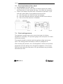
2 Introduction
Note: these instructions should be read carefully and retained for
future reference. Please leave these instructions with the user.
This guide is concerning the following types of appliances:
•
•
•
Widescreen interior:
MV100/MV200 interior:
MV150 interior:
Types Silence and Feeling
Type Spectra Nova and Whisper
Type Cadra Nova
Special features:
• Realistic flame and glow effect because of the "Flat Fibre Burner"
technology.
• Room sealed appliance, inlet and outlet are led to the outside using a
natural draught concentric pipe system (100 mm/150 mm) (no power
fan required). No additional ventilation required.
• Air supply and flue-gases go to outside atmosphere through wall or
roof. A maximum horizontal extension of 6 meters is possible.
• Remote Control option on all appliances.
• Meets the essential requirements of the European Gas Appliance
Directive (GAD) and carries the CE mark.
>>>>5
UK/IRL
3 Safety and general information
•
•
•
•
Before installation, ensure that the local distribution conditions
(identification of the type of gas and pressure) and the adjustment of
the appliance are compatible.
This gas appliance is factory set and shall not be adjusted by the
installer.
This appliance does not contain any component manufactured from
asbestos or any asbestos related products.
The pilot and flame sensing device fitted to this fire is also a safety
device. If for any reason any part of the pilot assembly is to be
replaced the entire assembly including the pilot burner,
thermocouple, electrode and injector must be exchanged complete
for a pilot assembly from the original manufacturer only.
Ventilation
This appliance is room-sealed and doesn't require purpose provided
ventilation.
3.1
General safety
It is the law in the UK that all gas appliances, are installed by a
competent person in accordance with the Gas Safety (Installation and
Use) Regulations (as amended), the relevant British Standards for
Installation work, Building Regulations, Codes of Practice and the
manufacturers instructions.
The installation should also be carried out in accordance with the
following where relevant:
•
•
•
•
BS5871 Part1
BS5440 Parts 1 & 2
BS1251.
Building Regulations Document J (as applicable).
Building Regulations and Standards issued as relevant by the Department
of the Environment or the Scottish Development Department.
6<<<<
UK/IRL
In the Republic of Ireland installation should be carried out in accordance
with IS813, ICP3, IS327, Building Regulations, Codes of Practice, the
manufacturers instructions and any other rules in force.
Failure to comply with the above could leave the installer liable to
prosecution and invalidate the appliance warranty.
Safety instructions for the user: see chapter 10.
>>>>7
UK/IRL
4 Installation requirements
Note:
Since the appliance is a source of heat, circulation of air occurs.
Therefore it is of importance that you do not use the appliance shortly
after a renovation of the home. Because of the natural circulation of air,
moist and volatile components from paint, building materials, carpet etc.
will be attracted. These components can settle themselves down onto
cold surfaces in the form of soot.
As on all heat producing appliances, soft furnishings such as blown vinyl
wallpaper placed too near to the appliance may become scorched or
discoloured. This should be born in mind when installing the appliance.
4.1
Builders opening and surround
The appliance can be installed in the following situations:
In a non-combustible fireplace or builders opening. This could be either
an existing builders opening or a new made prefab builders opening. For
the measurements, see figure 1 and index.
Although the appliance is tested for installation without a hearth, the
appliance must not stand on combustible materials or carpets. If the
appliance is placed on a combustible floor then a fibrelux or similar
heatproof board of 12 mm thickness should be placed under it. Any under
floor vents or openings within the builders opening should be sealed off.
Do not place the lintel, surround or marble stone directly onto the
appliance. If possible, apply a lintel made of cement or something similar.
Insulate the appliance with a ceramic blanket (25 mm). See also chapter
4: Installation instructions. Preferred choice for insulation is unbound
insulation wool (at 1000 °C gives no smell).
8<<<<
UK/IRL
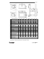
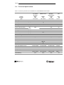
Builders opening (mm)
Feeling Sense
Silence
Ease
(BF100H)
Whisper
Spectra
Nova
Cadra
Nova
Misty
Builders opening (mm)
A Opening width
960
960
960
920
780
780
680
710
B Opening height
649
649
649
590
705
698
798
890
C Opening depth (min.)
385
385
385
397
430
430
430
370
Minimum height shelf
from top frame
E Depth shelf
350
350
350
350
350
350
350
350
150
150
150
150
150
150
150
Shelf dimensions
D
150
Dimensions of the appliance (mm)
F Box width
885
885
885
885
750
750
650
698
G Box depth
369
366
369
366
397
375
375
338
H Box height
605
605
605
605
714
715
815
879
I
Frame width
1064
1136
1064
985
815
794
694
740
J Frame height
678
750
678
599
720
703
803
905
K Frame thickness
47
57
20
36
16
30
30
144
255
255
255
255
257
235
235
196
111
111
111
111
140
140
140
142
17
-20
17
50
8
0
0
?
L Position flue collar
measured from frame
M Position flue collar
measured from back
N Height underside foot to
underside frame
O Height underside foot to
builders opening
≥ N (=dimensions in the row above)
table 1
*point A to C have a tolerance of -0 mm and +5 mm.
>>>>9
UK/IRL
If the builders' opening is constructed out of non-combustible composition
board (Fibrelux) and you install the appliance without a mantel then:
•
•
•
•
•
Ventilate the space above the appliance (min. 1000 mm2 ).
Always fit the DC convection set.
The plaster of the outside has to be resistant to a high temperature.
Use therefore the plaster materials especially made for this, to
prevent discolouring (min. 100 °C temperature resistant).
The plaster has to dry for at least 1 day per millimetre plaster. This
means that 4 mm plaster has to dry for at least 4 days before the
appliance should be used. This is to avoid cracking.
If the appliance is to be fitted against a wall with combustible
cladding, the cladding must be removed from the area covered by the
surround.
The minimum height from the top surface of the fire to the underside of
any shelf made from wood or other combustible materials is as follows:
•
•
•
4.2
•
•
•
For a shelf up to 150 mm deep – Minimum height = 350 mm (fig. 1).
If the shelf depth is greater than 150 mm add 50 mm to the upper
clearance height for every 25 mm increase in shelf depth.
Side clearance = Minimum distance from the side of the fire frame to
combustible material = 150 mm.
Flue requirements
The appliance is of the type C11/C31. The appliance will need to be
supplied with the approved flue pipes and terminal, it is not possible
to supply your own.
The minimum effective height of the flue system must be 0.5 or 1
meter, depending on the appliance.
Terminal locations, through the wall as well as through the roof. See
figure 3.
Flue routing;
• a horizontal extension with elbows is allowed for a maximum of 6
meters (depending on the type and situation).
10 < < < <
UK/IRL
•
vertical max. 12 meters.
Determine on the base of the table 2 and 3, depending on the type and
terminal position, if the desired situation is possible. To establish this you
will need to calculate:
•
•
The effective height (this is the real difference in height between the
upper side of the appliance and the terminal).
The total horizontal extension. This is the total horizontal flue length
where:
à each elbow, which is in the horizontal area, counts for 2 meters.
à each 45-degree bend, which is in the horizontal area, counts for 1
meter.
à elbows and bends at the transition of horizontal to vertically are
not to be counted.
à the wall mounted terminal counts for 1 meter.
Flue restrictor
If applicable, in the table is also stated the size of a flue restrictor. This
restrictor needs to be fitted in the combustion chamber when placing the
appliance (see chapter 4.2). Normally the smallest flue restrictor is fitted.
Example calculation 1:
Calculating horizontal extension fig. 2a:
Flue lenght C + E = 1m + 1m
2m
Elbows D = 2m
2m
Total horizontal extension
4m
Measure or calculate effective height
(Hvert)
Flue lenght A
1m
Roof mounted terinal
1m
Total effective height
2m
> > > > 11
UK/IRL
When calculating on basis of the Widescreen table nr. 2: It is allowed.
Remove the flue restrictor!
When calculating on basis of the MV100 table nr. 3: Allowed but without
flue restrictor. Remove the flue restrictor!
When calculating on basis of theMV150 table nr. 4: Allowed but without
flue restrictor. Remove the flue restrictor!
When calculating on basis of the Roundscreen table nr. 5: Allowed but
without flue restrictor. Remove the flue restrictor!
Example calculation 2
Calculation horizontal extension fig. 2b:
Flue lenght J + L = 0,5 + 0,5
1m
Elbows K + M = 2m + 2m
4m
Terminal
1m
Total horizontal extension
6m
Calculation effective height (Hvert)
Flue lenght H
1m
When calculating on basis of the
Widescreen table nr. 2: Combination not
allowed.
When calculating on basis of the MV100
table nr. 3: Allowed but without flue
restrictor. Remove the flue restrictor!
When calculating on basis of the MV150
table nr. 4: Combination not allowed.
4.3
Tables for determining the right flue restrictor
Calculate the total horizontal- and vertical length of the flue, according
to the calculations displayed above. Determine according to tables 2, 3, 4
and 5 on the following pages the right flue restrictor size. When meeting
12 < < < <
UK/IRL
an X, and when the values are outside the table, the combination is not
allowed. Normally the 30 mm flue restrictor is preinstalled.
> > > > 13
UK/IRL
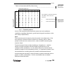
Table 2: Widescreen (Ease (BF100H), Feeling, Silence, Sense)
Vertical length in m
Horizontal length in m
0
1
1,5
2
3
4
5
6
7
8
9
10
11
12
0
1
2
3
4
5
6
x
0
0
30
45
45
50
50
60
60
65
65
65
65
x
0
0
30
45
45
50
50
60
60
65
65
65
x
x
x
0
0
30
30
45
45
50
60
60
65
x
x
x
x
x
0
0
30
30
30
45
50
60
x
x
x
x
x
x
x
0
30
30
30
45
50
x
x
x
x
x
x
x
x
0
0
30
30
30
x
x
x
x
x
x
x
x
x
x
0
0
0
x
x
x
x
x
x
Met opmaa
Engels (Gro
The numbers in the table represent
the width in mm of the flue restrictor
X
Combination NOT allowed
0
remove flue restrictor
Vertical length in m
Horizontal length in m
0
1
2
3
4
5
6
7
8
9
10
11
12
1
X
0
30
45
45
50
50
60
60
65
65
65
X
14 < < < <
2
X
0
0
30
30
45
45
60
60
60
65
X
X
3
X
0
0
0
0
45
45
50
60
60
X
X
X
4
X
0
0
0
0
30
30
50
50
X
X
X
X
5
X
0
0
0
0
0
0
45
X
X
X
X
X
6
X
0/X*
0
0
0
0
0
X
X
X
X
X
X
Met opmaa
Engels (Gro
Met opmaa
pt, Cursief,
(Groot-Britta
Table 3: MV100/MV200 (Spectra Nova, Whisper)
0
X
30
30
45
45
50
50
60
60
65
65
65
65
Met opmaa
pt, Cursief,
(Groot-Britta
Met opmaa
Engels (Gro
The numbers in the table represent
the width in mm of the flue restrictor
X
Combination NOT allowed
0
remove flue restrictor
Met opmaa
Engels (Gro
UK/IRL
Met opmaa
pt, Cursief
Vertical length in m
Tabel 4: binnenwerk MV150 (Cadra Nova)
0
0,5
1
2
3
4
5
6
7
8
9
10
11
12
Horizontal length in m
0
1
2
3
X
X
X
X
X
0
X
X
X
30
0
0
40
30
0
0
40
40
30
0
50
40
40
30
50
50
40
40
50
50
50
40
60
50
50
40
60
60
50
50
60
60
60
50
65
60
60
X
65
65
X
X
65
X
X
X
4
X
X
0
0
0
0
30
40
40
50
X
X
X
X
5
X
X
0
0
0
0
30
30
40
X
X
X
X
X
6
X
X
0
0
0
0
0
0
X
X
X
X
X
X
The numbers in the table represent
the width in mm of the flue
restrictor
X
Combination NOT allowed
0
remove flue restrictor
4.3.1 Terminal position
Verify if the required terminal position meets the local installation
regulations regarding disturbance, good functioning and ventilation. (Also
see: safety requirements).
Note:
The terminal must be located so that the outlet is not obstructed. If the
flue terminal is located within 2 meters of a footway, path or where
people could come into contact with it, then a suitable terminal guard
must be fitted.
Terminals located close to shared walkways, footpaths etc. could be
subject to legal constraints and this should be pointed out to the
customer before installation. If in any doubt about flue location advice
should be sought from local building control, or if appliance-related, from
the manufacturer including wherever possible a dimensioned sketch.
Avoid locating the terminal in close proximity to plastic materials such as
gutters or other combustibles. If this is unavoidable then a suitable
deflector should be made.
> > > > 15
Met opmaa
Engels (Groo
UK/IRL
Some important requirements for a good functioning are:
The wall-mounted terminal has to be at least 0,5 m off:
à Corners of the building.
à Below eaves.
à Balcony's etc. unless the duct is dragged to the front side of the
overhanging part.
The roof mounted terminal has to be at a distance of at least 0.5 meters
of the sides of the roof, excluded the ridge.
16 < < < <
UK/IRL
Flue terminal
Fig. 3
Met opmaa
pt, Cursief
Table 5
Dimension
Terminal position
(kW input 7.5 kW expressed in net)
Balanced flue
room sealed
Natural Draught
A
Direct below an opening, airbrick, opening
windows, etc.
300
mm
B
C
Above an opening, airbrick, opening window, etc.
Horizontally to an opening, airbrick, opening
window, etc.
300
300
mm
mm
D
E
F
G
H
I
J
K
L
Below gutters, soil pipes or drain pipes
Below eaves
Below balconies or cat port roof
From a vertical drain pipe or soil pipe
Dfrom an internal or external corner
Above ground roof or balcony level
From a surface facing the terminal
From a terminal facing a terminal
From an opening in the carport (e.g. window) into
the dwelling
500
500
600
300
600
300
600
600
1200
mm
mm
mm
mm
mm
mm
mm
mm
mm
M
N
P
Q
Vertically from a terminal on the same wall
Horizontally from a terminal on the same wall
From a vertical structure on the roof
Above intersection with roof
1500
300
600
500
mm
mm
mm
mm
> > > > 17
UK/IRL
Example of how terminal position is measured
Fig. 4
4.3.2 Using an existing chimney as air inlet
You can connect the appliance onto an existing chimney. The existing
chimney then functions as air supply, where a flexible stainless steel liner
(to BS715) of 100 mm performs the flue function.
Requirements:
• Any existing chimney used as an air supply must only service this
appliance.
• A chimney that has previously been used for solid fuel must be swept
before use.
• The existing chimney needs to be airtight.
• The existing chimney needs to have an opening of min. 150 x 150 mm.
• The chimney needs to be intact and well looked after.
• Use the adjustable roof-mounted-terminal especially made for this,
and the chimney connection set.
• The min. distance between two terminals should be at least 450 mm.
18 < < < <
UK/IRL
5 Instructions for installation
5.1
Gas Connection
1)
Installation pipes should be in accordance with BS 6891. Pipe work
from the meter to the appliance must be of adequate size.
2)
The complete installation including the meter must be tested for
soundness and purged as described in the above code.
3)
A means of isolation must be provide in the supply to facilitate
servicing.
4)
The connection should be made in 8 mm copper or similar semi
flexible tube. (max 1 meter). Ensure that the gas pipe does not
interfere with the removal or replacement of the burner tray of the
controls.
5)
The gas connection is nut and olive suitable for 8 mm pipe.
5.2
Preparing the appliances
Before you can install the appliance properly, it is wise to prepare the
appliance, because you still have access to all parts of the appliance.
These will be barely reachable once the appliance is installed. In the next
paragraphs these preparations will be described for the different models.
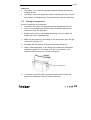
1)
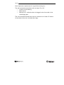
5.2.3 Preparing all Widescreen models and MV200
Open the ashtray door by pushing on the right side for the
Silence/Feeling and on the left side for the Whisper. Remove the
> > > > 19
UK/IRL
frame by loosening the screws A behind the door (see fig. 6). Lift and
pull forward and take it away.
Fig. 6
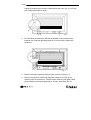
2)
For the Sense and the Ease: Pull the underside of the (inner) frame
towards you. Push the blocking strips up. Lift the (inner) frame and
remove it.
Fig. 7
3)
Remove the back panel by loosening the screws B (see fig. 7).
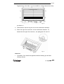
4)
Remove the glass by removing the glass clamps C (see fig. 8) for
instance with a screwdriver. Careful when removing the glass! Wear
gloves! Before placing the glass back, be sure that there are no
20 < < < <
UK/IRL
fingerprints on the glass, it is not possible to remove them when they
Fig. 8
are burnt in.
5)
Take the box with the log set out of the combustion chamber.
6)
Place the right flue restrictor in the combustion chamber. To
determine the right flue restrictor, see paragraph 4.2 and 4.3.
Fig. 9
Attention:
y
If possible, first install the appliance before building up the false
chimney breast.
> > > > 21
UK/IRL
y
1)
If possible, install the appliance, before installing the flue. If this is
not possible, a slidable piece of pipe should be used as a connection.
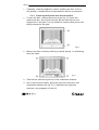
5.2.4 Preparing the Spectra Nova and Cadra Nova
To open the door, remove the screws A (see fig. 10). Open and
remove the door; lift and pull forward. Be sure that there are no
fingerprints on the glass. It is not possible to remove those prints once
they are burned in the glass.
A
A
2)
Fig.10
Remove the outer frame by removing screws B (see fig. 11) and taking
away the frame.
Fig.11
3)
Take the box with the log set out of the combustion chamber.
4)
Like in the previous models, place the right flue restrictor in the
combustion chamber (see fig. 9). To determine the right flue
restrictor, see paragraph 4.2 and 4.3.
22 < < < <
UK/IRL
Attention:
• If possible, first install the appliance before building up the false
chimney breast.
• If possible, install the appliance, before installing the flue. If this is
not possible, a slidable piece of pipe should be used as connection.
5.3
Placing the appliance
Points of attention for placement:
• If possible, first place the appliance before assembling the flue.
• If this is not possible then always use an extendible pipe before
connection onto the appliance.
1)
Position the firebox in the fireplace opening. You can adjust the
height with the 4 adjustable feet.
2)
Make the gas connection according to the instructions (also see gas
connection, chapter 5.1).
3)
Assemble the flue system onto the firebox (see chapter 5).
4)
Check, when applicable, if the safety hatch seals the combustion
chamber properly. Do not fasten it at all! If you fasten it, the
explosion safety hatch won’t function properly!
Fig.13: Safety hatch
5)
If necessary, place the DC convection system (also consult the
instruction belonging to the DC construction set).
> > > > 23
UK/IRL
6)
7)
If necessary, isolate the firebox with a ceramic blanket (25 mm).
Preferred choice for insulation is unbound insulation wool (at 1000 °C
gives no smell).
Place the log set (see placing log set, chapter 5.4).
8)
Spread, the bags of embers (imitation ashes) provide with the
appliance over the burner tray. Attention! No embers on the grid end
between the logs and the burner tray!
9)
Before placing the glass; check the glass sealing rope is in good
condition and makes an effective seal. Be sure that there are no
fingerprints on the glass. It is not possible to remove those prints once
they are burned in the glass:
•
•
10)
Widescreen and Whisper; Place the glass in front of the appliance
and fix it with the glass clamps. Replace the frame.
Cadra Nova and Spectra Nova: Place the door and fix it. Check on
visual leakages around the door sealing.
Widescreen: Fix the outer frame with 4 screws.
After installation, let the appliance burn for max. an hour. Afterwards,
check the glass for possible dirt , dust and other deposit and remove it.
5.4
Placing the log set
Never place extra elements of any kind into the combustion chamber. To
guarantee good combustion, the log set may only be installed in the way
specified by Faber International BV. Any other arrangement can lead to
soot on logs or window. Do not use the fire with broken or missing logs.
5.4.1 Embers
There are 4 different types of imitations ashes provided with the
appliance.
Type 1: To spread over the burner to achieve the glowing affect
Type 2: Yellow bark
Type 3: Anthracite bark
Type 4: Vermiculite corn
24 < < < <
UK/IRL
Type 2, 3 and 4 are only for decoration purpose, don't put them on the
burner.
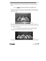
5.4.2
Placing the log set Spectra Nova, Cadra Nova and
Whisper
The log set consists of a rear log, which is permanently attached to the
combustion chamber, and four logs. The logs must rest on the log holder
and the rear log.
Fig 15
Ensure that the pilot burner remains visible after installation of the log
set. When not placing the log set correctly, the flames tend to burn to the
front against the window.
5.4.3 Placing the log set Feeling, Silence, Sense and Ease
The log set consists of two rear logs and six ceramic logs.
Fig. 16
Put the two rear logs on the tray at the back of the combustion chamber.
> > > > 25
UK/IRL
Put the others exact as showed on the picture. On the front the logs must
lay at the holes, on the back they rest on the rear logs.
5.4.4 Placing the pebble set Ease
Spread the pebbles over the bottom of the combustion chamber. Make
sure that the pilot is not covered or blocked by the pebbles. See fig 17 for
more details.
Fig. 17
26 < < < <
UK/IRL
6 Installation of the flue
6.1
1)
Connection with use of concentric duct material
Build the system starting from the appliance on.
2)
Make a hole of ø 153 mm for the wall or roof mounted terminal.
3)
Make sure you place the pipes in the right direction, the narrow end
towards the appliance.
4)
Make sure the pipes are fixed sufficiently, a wall clamp every 2m, so
the weight of the pipes is not resting onto the appliance.
5)
The outside of the pipe can become hot (140 degrees). Stay 50 mm
away from wall surface or sealing. Make sure to provide sufficiently
heat resistant isolation when going through the wall or roof.
6)
Because of expansion or cooling down the concentric pipes can turn
loose. It is recommended to fix the spring clip with a self tapping
screw at inaccessible places.
7)
To get the exact measure flue length you can use cut down concentric
pipe, wall mounted terminal or roof mounted terminal. To obtain a
smoke sealed connection, the inner pipe must be 20 mm longer then
the outside pipe.
8)
The horizontal pipes need to rise away from the appliance at a rate of
3 degrees per metre.
6.2
Connection onto an existing chimney
You can connect the appliance onto an existing chimney. The existing
chimney then functions as air supply, where a flexible stainless steel liner
(to BS715) of 100 mm performs the flue function. Any existing chimney
used as an air supply must only service this appliance.
Requirements:
• 300 mm of free space above the appliance;
• The chimney only supply’s air to this appliance;
> > > > 27
UK/IRL
•
•
•
The existing chimney needs to be clean and very well swept;
The existing chimney needs to be airtight;
The existing chimney needs to have an opening of min. 150 x 150 mm.
Parts needed for this kind of installation:
• Chimney connection set part number
A9225000 Fig 20 part D.
• Short roof terminal part number
A9266100 Fig 19 part B
• Chimney closure plate part number A
9240000 Fig 19 part A
• Two stainless steel tubes one 100 mm length 500 mm and one 150 mm - length
500 mm part number A 9273900 Fig 19
part E and F
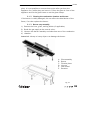
Installation:
1) Place the aluminium closure plate (A)
onto the chimney. Permanently attach
and make airtight.
2)
Pull the liner (C) through the chimney.
3)
Connect the liner onto the roof terminal
and fix this with the clamp provided with
the chimney connection set.
4)
Place the roof terminal onto the closure
plate.
5)
Fixing the chimney sealing plate (D) and
place the 150 mm grommet into the hole
of the sealing plate.
6)
Fix the sealing plate air tight into the builders opening (use isolation
rope from the chimney connection set to make the plate air tight).
7)
Slide pipe (E) 150mm length 500mm into the sealing plate. Slide this
pipe so that you have enough space later on to assemble the liner.
28 < < < <
Fig. 18
UK/IRL
8)
Install the appliance.
9)
Connect the flexible stainless steel liner onto the appliance using the
100mm pipe (F) as adapter.
10)
If the distance from the flue outlet to the sealing plate is bigger then
300 mm, you have to use a concentric pipe first.
11)
Slide the outside pipe onto the appliance or concentric extension so
that you have a air tight connection.
6.3
Remote control (when applicable)
The remote control is only meant to regulate the flames, it functions only
when the pilot burner is ignited. It is therefore not possible to ignited the
appliance with the remote control or to shut-off the pilotflame.
The radio-frequency remote control is intended for fireplaces installed in
a domestic setting in all EU countries except Austria, Denmark, Finland
and Greece.
Features:
-
Manual control will always remain possible.
The remote control is a radio frequency type and has been approved
internationally.
The remote control generates a unique safety code every time you
activate the transmitter, its similar to those used in a car.
The remote control is easy to install retrospectively.
6.3.1 Installation
1) Connect the transformer to the receiver box. The adapter is set to the
correct voltage in the factory 4.5 V.
Fig 19
> > > > 29
UK/IRL
2) Slide the receiver box into the holder.
3) Connect the wires to the gas control (see fig.20 ).
Fig. 20
4) Check ifthere are batteries in the transmitter. See "Replacing
batteries", see chapter 10.4.4.
5) Set the on/off switch on the receiver to "on".
Setting the right transmission code
The receiver has to learn the code from the transmitter, which is already
done at the factory. However the code disappears if the receiver is
disconnected from the mains for a longer period.
1) Push the "mod" button on the receiver and hold it for 3 seconds.
2) The green control lamp will light up and stay on. Repeat this step if it
doesn't.
3) Push a button on the remote control. The control lamp on the
receiver should now go out.
4) Again push a button on the remote control. The lamp starts flashing
and will switch off eventually.
5) The receiver now recognizes the remote control. The remote control
now functions.
6) Check if you can hear a sound and the motor runs when you push a
button on the remote control.
30 < < < <
UK/IRL
7 Commissioning (functional checks)
7.1
1)
2)
3)
4)
Check pilot ignition
Push in and turn the control knob (a) from anti-clockwise to the
setting (small flame). You will hear a tick, meaning there is ignition.
Hold the knob in and wait for a few seconds while the air is purged;
Bring the knob back in start position and turn the knob several times
to the position. Check if the pilot has lit;
Continue to hold in the control knob for a further 10 seconds to
ensure that the pilot flame is stable;
Release the knob. The pilot should remain alight. If not, repeat the
previous steps.
Fig. 21
7.2
Functional burner check
1)
Turn knob (B) to max. clockwise;
2)
Turn knob (A) more anticlockwise to the
it’s possible to light the main burner;
3)
Turn knob B anticlockwise to its max. The main burner should light.
Check for gas soundness at all joints with leak detection fluid.
4)
Check the ignition of the main burner on low and high setting;
5)
Turn knob B clockwise till . The main burner is off;
6)
Turn knob A to . The pilot should go out.
position (large flame). Now
> > > > 31
UK/IRL
7.3
1)
2)
3)
Functional balanced flue check
Set the appliance on max. input;
Verify the flame picture, this means no flames against the window,
the flame have to come besides the logs, if not check the log layout.
Check if the flames are yellow after 10 minutes of operation. If you
still have a blue flame or the appliance goes out check:
a) If the flue pipes are fitted correctly (no leakage).
b) If the wall mounted terminal is placed with the correct side up.
c) If the correct flue restrictor is installed.
D C
7.4
B
A
Fig. 22
Check setting pressure
The appliance is preset to give the correct heat input. No further
adjustment is necessary. Fit a pressure gauge at the test point D to check
the burner pressure.
The pressure should be checked with the appliance alight and at max
input. The setting pressure should be as shown in paragraph 9.4 .
After checking the pressure, turn off the appliance. Remove the pressure
gauge and close the sealing screw. Re-light the appliance. Turn to max.
input and test around the test point D for gas soundness using a suitable
leak detection fluid.
32 < < < <
UK/IRL
8 Handing over (final check and customer briefing
-
Instruct the customer on the full operation of the appliance.
-
Advise the customer how to clean the appliance including the glass.
-
Instruct the customer on the operation of the remote control,
including replacement of batteries and how to set the right
transmissions code.
-
Hand over these instructions including the user guide to the
consumer.
-
Recommend that the appliance should be serviced by a competent
person at least once a year.
> > > > 33
UK/IRL
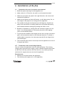
9 Servicing
To ensure safe, efficient operation of the appliance, it is necessary to
carry out routine servicing at regular intervals.
It is recommended, that the fire is inspected/serviced by a competent
person at least once a year.
Important
Turn off the gas supply before commencing any servicing. Always test
for gas soundness after refitting the appliance!
9.1
Routine anual servicing
1) Clean (if necessary):
a. the pilot system;
b. the burner;
c. the combustion chamber;
d. the glass.
2) Check the log lay and replace the embers (if applicable).
3) Do the functional test as described at page 32.
4) Check the flue system and terminal on damage and soundness (visual
inspection).
9.1.1 Cleaning the glass
Depending on the intensity of use, you can get a deposit on the glass. This
can be removed with a special ceramic glass cleaner (ceramic cook-top
cleaner) as follows:
1) Remove the front and the back.
2) Clean the glass. Handle the glass with clean hands, wear gloves if
possible.
3) To fit the glass, proceed in reverse order. Make sure that the log set
has been installed correctly before fixing the glass.
Attention:
Before placing the glass: check the glass sealing rope is in good condition
and makes an effective seal. Be sure that there are no fingerprints on the
34 < < < <
UK/IRL
glass. It is not possible to remove those prints after you burn the
appliance for a while (they are burnt in). Place the glass in front of the
appliance and fix the glass frame or use the glass clamps.
9.1.2 Cleaning the combustion chamber and burner
If the burner is visibly damaged, this can affect the distribution of the
flame, if so then replace the burner.
1)
2)
3)
4)
9.1.3 Burner tray assembly
Remove the front, glass, and log holder (if applicable)
Break the gas supply at the control valve.
Unscrew the burner assembly and take them out of the combustion
chamber.
Attention! A sharp or heavy object can damage the burner.
A.
B.
C.
D.
E.
F.
Pilot assembly
Burner
Fixation plate
Injector
Gas control
Receiver
Fig. 23
> > > > 35
UK/IRL
9.1.4 Pilot/thermocouple assembly
Fig. 24
This is not a serviceable item, both thermocouple and pilot should be
replaced together.
Pilot/thermocouple assembly
1) Remove the burner tray.
2) Remove the lead from the pilot spark igniter.
3) Break the gas pipe connection to the pilot.
4) Unscrew thermocouple nut from the rear of the gas control.
5) Unscrew pilot assembly from the burner tray (2 screws)
6) Replace and re-assemble in reverse order.
9.1.5 Gas control block
D C
A
B
C
D
B
A
Govenor;
Adjustable screw pilot flame;
Inlet pressure test point ;
Burner pressure test point.
9.1.6 Combustion test
A BS7967 combustion analysis check should be carried out using an
analyser to BS7927 positioned in the flue outlet.
36 < < < <
Fig. 25
UK/IRL
A Ratio of CO/CO2 should be less than 0.01 within 30 minutes. (100 ppm
CO per 1% CO2).
A reading of CO in the room centre should give a rise of less than 9ppm
over ambient, peak reading.
9.2
Propane conversion
For conversion from propane to natural gas (or the other way around), you
have to order a complete new propane burner unit. Contact your supplier
and give the serial number from the data plate when you order.
9.3
List of spare parts
Table 6: List of spare parts
Whisper
Number
Omschrijving
A9271453
Surround Antracite
X
Surround St. Steel
X
Surround Bronze:
X
- inner frame
X
- outer frame
04508200
Glass
X
Glass operation
20521405
Burner NG
20773200
Log set
X
Pebble set
06017300
Spark wire
20604000
Receiver
20603900
Remote control
20900142
Adapter
37003089
Gas control
Motor Remote control 37003086
37001042
Oxypilot
37002033
Thermocouple
06006600
Bougie
20793400
Embers
09000008
Lack spray for
combustion chamber
X
Lack spray for front
20900008
Glass clamps
Touch Latch assembly 28103900
Feeling
Sense
Silence
Ease
Ease
(Bf100 H)
FFB
(Bf100 H)
PB
Spectra
Nova
Cadra
Nova
Number
Number
Number
Number
Number
Number
Number
A9270053
X
A9267753
20847648
20847648
A9274149
A9274149
X
X
X
20848003
20848003
X
X
X
X
X
X
X
X
X
X
20837393
X
X
X
X
X
X
20837493
X
X
X
X
X
04508300
04508300
04508300
04508300
04508300
0450950
04509300
X
X
X
X
X
09509600
04509400
20525905
20525705
20525905
20900240
20900241
20521405
20522605
20794500
20794500
20794500
20794500
X
20773200
20794500
X
X
X
X
20799100
X
X
06017300
06017300
06017300
06017200
06017200
06017300
06017300
20604000
20604000
20604000
20604000
20604000
20604000
20604000
20603900
20603900
20603900
20603900
20603900
20603900
20603900
20900142
20900142
20900142
20900142
20900142
20900142
20900142
37003089
37003089
37003089
37003089
X
37003089
37003089
37003086
37003086
37003086
37003086
37003086
37003086
37003086
37001042
37001042
37001042
37001042
37001042
37001042
37001042
37002033
37002033
37002033
37002033
37002033
37002033
37002033
06006600
06006600
06006600
06006600
06006600
06006600
06006600
20793400
20793400
20793400
20793400
20793400
20793400
20793400
09000008
09000008
09000008
09000008
09000008
09000008
09000008
X
X
X
09000014
09000014
X
X
20900008
20900008
20900008
X
X
X
X
28103900
X
28103900
X
X
X
X
> > > > 37
UK/IRL
9.4
Technical Specifications
Table 7: Technical specifications of the Widescreen, MV100/MV200 and the MV150
Ease
Pebble burner
Country
Category
Widescreen
(incl. Ease)
Flat Fibre
UK/IRL
I2H
Type
Type of gas
Heat input Hi
Efficiency class
NOX class
Working pressure
Gas rate
At 15º C and 1013 mbar
Setting pressure
Injector size
Reduced input restrictor
[kW]
[mbar]
[l/h]
gram/h
[mbar]
[mm]
[mm]
Gasaansluiting
Afmetingen zie tabel1
38 < < < <
C11 of C31
C11 of C31
C11 of
G20
6.1
2
4
20
G20
7.1
2
20
750
G20
7,2
2
4
20
G2
6.1
2
4
20
640
540 gram
10
2.2
1.6
63
800
10
2.55
1.8
Oxy-pilot
9709M NG
OP9709
Oxy-pilot
9709M NG
mm
mm
100-150
30
GV3636C5AOEHC68M
100-150
30
GV3636C5AOEHC68M
100-150
30
GV3636C5AOEHC68M
10030
GV36
C5AOEH
V
V
4.5
2x 1,5V Alkaline
8 mm nut and
olive
4.5
2x 1,5V Alkaline
8 mm nut and
olive
4.5
2x 1,5V Alkaline
8 mm nut and
olive
4.5
2x 1,5V A
8 mm n
oliv
Gas control Maxitrol GV 36
Remote control
Voltage adapter
Batteries remote control
C11 of C31
UK/I
I2H
13
2.4
1.8
Pilot Assembly
Type
Code
Flue system
Ø MVr
Preinstalled flue restrictor
MV150
Nov
UK/IRL
I2H
MV100 / MV200
Whisper /
Spectra Nova
UK/IRL
I2H
10.
2.2
1.6
Oxy-p
9709M
UK/IRL
User Manual
> > > > 39
UK/IRL
10 Safety instructions for the user
If a gas leak is found or suspected, turn off the gas supply at the meter
and contact your installer or gas emergency service.
These instructions should be read carefully and retained for future
reference.
Do not use the fire with a broken or damaged glass.
The fire has a safety device which turns off the gas supply if there is a
build up from flue gasses in the combustion room or a temporary gas cutoff. Wait at least 5 minutes before turning the appliance on again.
Contact a qualified installer when the appliance goes off regularly.
The appliance has been designed for heating purposes. This means that all
surfaces, including the glass, can become very warm (over 100 °C). An
exception to this is the lower side of the door and the control buttons.
Due to the newness of materials, they may give off a slight smell for a
period after initial lighting. This is normal, odours will disperse after a
few hours use.
Do not place curtains, clothing, laundry, furniture or other flammable
materials nearby the appliance. The required minimum distance is 100
cm.
Switch off the receiver of the remote control if you don’t use the fire for
a long time. Do not let children use the remote control without
supervision.
IMPORTANT
A suitable Fireguard conforming to BS6539 and BS6778 should be used
with this appliance to protect children, the elderly or infirm. Care should
also be taken with pets.
In your own interest and that of safety, all gas appliances must be
installed by competent persons. Installation must be in accordance with
National Regulations. CORGI registered installers are required to work to
recognised standards.
40 < < < <
UK/IRL
Note:
Since the appliance is a source of heat, circulation of air occurs.
Therefore it is of importance that you do not use the appliance shortly
after a renovation of the home. Because of the natural circulation of air,
moist and volatile components from paint, building materials, carpet etc.
will be attracted. These components can settle themselves down onto
cold surfaces in the form of soot. As on all heat producing appliances, soft
furnishings such as blown vinyl wallpaper placed too near to the appliance
may become scorched or discoloured. This should be born in mind when
installing the appliance.
> > > > 41
UK/IRL
11 Controlling the appliance
11.1 Lighting the fire
If the main burner or pilot light are extinguished for any reason, do not
attempt to relight the pilot within 5 minutes. Contact a qualified
installer when the appliance goes off regularly.
The control valve is behind the ashtray door.
Silence /Feeling /Whisper
Open the ashtray door by pushing on the right side for the Silence/Feeling
and on the left side for the Whisper.
Sense (remote control only)
Access to the controls by pulling the inner frame forwards.
Cadra Nova and Spectra Nova
Open by pushing the lip located on the right side in the gap between the
Fig. 26
ashtray door and the frame (door flaps open).
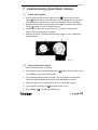
With control button A you can light the pilot. With the control button B
you can adjust the height of the flames (see fig. 26).
Knob A
is the OFF position preventing any gas from passing through the
The
control valve to either the pilot burner or to the main burner. By pressing
the knob in it is possible to turn it anticlockwise. The first function is to
turn on the gas to the pilot- this occurs just before reaching the
42 < < < <
UK/IRL
position (if the fire has not been lit for some time it may be necessary to
hold the knob in this position for some seconds to clear the air from the
pipe and allow gas to reach the pilot burner). Once gas is available at the
pilot, continued rotation anti-clockwise will cause the piezo igniter to
spark. This is accompanied by a click at the valve and should result in the
pilot burner igniting. Once the pilot is lit, the control
knob should be held pressed in for 10 seconds. In this time the pilot flame
will have heated the flame supervision thermocouple sufficiently to
operate a hold-on magnet within the valve. Now turn the control knob A
to the position. This allows gas to enter control knob B.
Knob B
The is the OFF position preventing gas entering the main burner if the
pilot is lit. The knob should be turned slowly anticlockwise. This allows
gas to enter the burner and be ignited by the pilot flame. Once ignition
has taken place, the fire may be set to any level between min. and max.
by adjusting the control knob B.
11.2 To light
1) Push in and turn the control knob (A) from anticlockwise to the
setting (small flame). You will hear a ignition click. Check that the
pilot is lit (if not repeat).
2) Continue to hold in the control knob for a further ten seconds to
ensure that the pilot flame is stable.
3) Release the knob. The pilot should remain alight.
4) Turn the control knob A to the
position.
5) Turn knob B slowly anticlockwise, the fire should then ignite.
6) Adjust flames to the required level.
11.3 To extingish
1) For the main burner turn the control knob B clockwise to position .
2) To disable knob B turn knob A to the position .
> > > > 43
UK/IRL
3) To extinguish the pilot turn control knob A to position , although it is
in order lo leave the pilot permanently lit.
When the pilot extinguishes
Warning! When the pilot extinguishes, for whatever reason, you should
wait at least 5 minutes before trying to turn it on again.
Possible causes of pilot extinguish are:
- Operating error.
- Interference of the safety device.
- Failure in the pilot flame system.
Contact a qualified installer when the appliance goes off
regularly.
11.4 Remote Control (when applicable)
The remote control is only meant to regulate the flames from
off till max. It functions only when the pilot burner is ignited
and knob A is in (big flame) position. It is therefore not
possible to ignite the pilot flame with the remote control or to
extinguish the pilot flame. The radio-frequency remote control
is intended for fireplaces installed in a domestic setting in all
EU countries except Austria, Denmark, Finland, and Greece.
Features:
- Manual control will always remain possible.
- The remote control is a radio frequency type and had been
Fig. 27
approved internationally.
- The remote control generates a unique safety code every
time you activate the transmitter, its similar to those used in a car.
- The remote control is easy to install retrospectively.
11.4.1 To light
1) Push in and turn the control knob (A) from { anticlockwise to the
setting (small flame). You will hear a ignition click. Check that the
pilot is lit (if not repeat).
44 < < < <
UK/IRL
2) Continue to hold in the control knob for a further ten seconds to
ensure that the pilot flame is stable.
3) Release the knob. The pilot should remain alight.
4) Turn the control knob A to the position.
5) Set the on/off switch on the receiver to "on”.
- low flame
- high flame
6) Use the
effect.
and
buttons to achieve the desired heating and flame
7) You will hear a beep every time the receiver recognises a good signal.
(If not, so see 10.4.3, setting the right transmission code).
8) When the fire is not be used for a prolonged period, turn off the pilot
(see 10.4.2)
11.4.2 To extinguish
1) Push (low) till the burner goes out and you can hear the motor
clicking.
2) To enable the remote control turn knob A to the
position.
3) To extinguish the pilot turn control knob A to position , although it is
in order to leave the pilot permanently lit.
11.4.3 Setting the right transmission code
The receiver has to learn the code from the transmitter, which is already
done at the factory. However the code disappears if the receiver is
disconnected from the mains for a longer period.
1) Set the on/off switch on the receiver to "on".
2) Push the "mod" button on the receiver and hold it for 3 seconds.
3) The green control lamp will light up and stay on. Repeat this step if it
doesn't.
> > > > 45
UK/IRL
4) Push a button on the remote control. The control lamp on the
receiver should now go out.
5) Again push a button on the remote control. The lamp starts
flashing and will switch off eventually.
6) The receiver now recognizes the remote control. The remote
control now functions.
7) Check if you can hear a sound and the motor runs when you
push a button on the remote control.
11.4.4 Changing batteries
There is no risk of electric shock as the low voltage supply is
similar to that used in torches. Always turn off the appliance
before changing batteries.
Remote control
1) Remove the cover on the back of the remote control.
2) Carefully remove the battery clip along the side. Pay
attention not to pull the wires.
3) If necessary, remove the old batteries and place the new
ones: 2x LR03 Alkaline long life 1.5 V.
4) Click the battery clip into the remote control and close the
cover.
5) It might be possible that you have to set the transmission
code after changing the batteries (see 10.4.3).
Note
Batteries are chemical waste and should be disposed in
accordance with local regulations.
46 < < < <
Fig. 28
UK/IRL
12 Cleaning and service instructions
Important:
Turn off the fire and allow it to cool down before commencing
cleaning.
It is recommended that the fire is inspected/serviced, by a competent
person at least once a year.
To maintain the finish on the trim wipe with soft damp cloth only. Do not
use abrasive cleaners, polish or solvents as these can damage the surface
finish.
> > > > 47
UK/IRL
13 Disposal of packaging and appliance
The appliance packaging is recyclable. The packaging could include the
following materials:
-
cardboard;
CFC-free foam (soft);
wood;
plastic;
paper.
These materials should be disposed responsibly and in conformity with
government regulations.
Batteries are considered chemical waste. The batteries should be
disposed of responsibly and in conformity with government regulations.
Remove the batteries before disposing of the remote control.
Information on how to responsibly dispose of discarded appliances can be
obtained from the local authorities.
48 < < < <
UK/IRL
Saturnus 8
NL - 8448 CC Heerenveen
P.O. Box 219
NL - 8440 AE Heerenveen
T.
+31(0)513 656500
F.
+31(0)513 656501
> > > > 49


![User Manual BS 15 [ASL]](http://vs1.manualzilla.com/store/data/005675346_1-422b291500c6ff99ebe2f8b515793259-150x150.png)