1
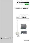
ARTS User Manual
v1.1
Altimeter Recording & Telemetry System
© 2003 Ozark Aerospace LLC
Table of Contents
I.
Introduction ........................................................................ 2
II.
Mounting the ARTS .......................................................... 4
III.
Configuring the ARTS ..................................................... 5
IV.
Pre-Flight ............................................................................. 8
V.
Post-Flight........................................................................... 8
VI.
Downloading / Analyzing Data ..................................... 8
VII.
Saving / Loading / Exporting Data ............................13
VIII.
Altimeter Diagnostic Functions .................................13
IX.
Advanced Diagnostics ..................................................14
Appendix A
Telemetry Subsystem...................................15
Appendix B
Terminal Communications..........................21
Appendix C
Sensors..............................................................31
Appendix D
Connector Pinouts.........................................33
ARTS Warranty, Terms and Conditions ..............................34
I.
Introduction
Thank you for purchasing the ARTS flight computer by Ozark
Aerospace. Please read this manual carefully and completely
before using the ARTS and we highly recommend gaining some
flight experience by using the ARTS with a backup, or for data
collection only, before going "solo" with it.
Precautions
?? The ARTS contains parts that are sensitive to damage
from ESD (electro-static discharge). Always ground
yourself before handling the ARTS. ESD damage is
not covered under warranty.
?? Always allow the ARTS and the battery to adjust to
ambient temperature prior to arming and flying.
?? Never handle or move the rocket or the ARTS when the
ARTS is armed and connected to live pyrotechnic
charges as this may cause the premature firing of the
charges.
?? Never arm the ARTS when connected to live
pyrotechnic charges until the rocket is on the pad and in
the firing position.
?? When fired, the current on the output channels is 1.25
amps for 0.25 seconds. This is sufficient for low
current electric matches, such as those made by
Daveyfire and Oxral. Other igniters may not work
reliably, or at all. Don't assume that because it worked
with another altimeter it will work with the ARTS.
Igniters can be tested by using the diagnostics panel in
the DataAnalyzer program to fire the outputs.
2
The ARTS Flight Computer
1
8
2
3
5
4
This end up
7
6
1 – Terminal Connector: Connect to your computer using the supplied serial
cable
2 – GPS Connector: Connect to an NMEA2.0 capable GPS to report your
rocket’s position over the telemetry
3 – Programming header: used during production to load firmware
4 – AUX connector: Expansion connector for future enhancements (igniter
expansion and telemetry are in production)
5 – Power switch connector
6 – 9V Battery connection, be sure to note polarity marks on board
7 – Option switches:
SW1 (left) selects flight profile 1 (on) or 2 (off)
SW2 (right) selects flight data bank 1 (on) or 2 (off)
8 – Output channel terminals. Channel 1 Apogee, Channel 2 Main
3
II.
Mounting the ARTS
?? Select a location within
the rocket for the ARTS
that is protected from
ejection gasses and is
vented to external
pressure.
?? The ARTS must be
mounted vertically with
the arrow on the board
facing up when the
rocket is in the firing
position.
?? The ARTS is supplied
with two ½” standoffs
and #6 machine screws
that can be placed either
on the front or back of
the board. Alternatively,
the four corner holes can
be used with #4 machine
screws.
The ARTS must be rigidly mounted! The ARTS uses
the accelerometer to detect both liftoff and apogee.
The ARTS will only function properly when securely
mounted.
4
Use a fresh 9V alkaline battery. A snap type battery clip can be
used. However, a more reliable method is to solder wires directly
to the battery terminals. Observe the correct polarity when
attaching the battery to the ARTS, plus is marked on the board.
Connecting the battery does not power up the ARTS. There are
separate power and switch connectors and when the switch is off,
there is no load on the battery. The switch connector should be
connected to an external switch for arming. Choose a high quality
switch.
Use caution with the output channels!
?? Always wear eye protection when working with live
pyrotechnic charges.
?? Always shunt charges and igniters until the rocket is in the
firing position
?? Do not arm the ARTS until the rocket is on the pad and in
the FIRING POSITION! Unlike some other
accelerometers, the baseline readings are taken only at
power up and are not updated continuously.
III.
Configuring the ARTS
One of the most powerful features of your ARTS system is the
ability to program the 2 output channels. Each output channel can
respond to any of 4 events: Launch, Main Engine Cutoff (MECO),
Apogee, and Altitude. Also, a specific time delay between the
event and the activation of the output channel can be set. The most
basic configuration would have Channel 1 set to fire 0.0 seconds
after apogee and Channel 2 set to fire 0.0 seconds after a specified
Altitude, say 800 feet.
The ARTS can hold two different flight profiles. They are selected
via DIP Switch 1. These profiles allow the ARTS to quickly
change functions without having to attach a laptop. Profile 1 is an
Apogee / Altitude only profile, while Profile 2 is fully
customizable.
5
Also configurable is the sampling rate. Higher sampling rates
increase the number of data points, but decrease the recording
time. The recording time is displayed next to the sampling rate in
the profile screens. If the recording time is too short for your
flight, simply decrease the sampling rate.
To set these values, start up DataAnalyzer, connect the ARTS
using the serial cable to your computer, and power it on. Select
Altimeter > Configuration, or click the
screen. You will see:
icon on the main
You should first click on “Load from Altimeter” first to verify the
settings that are currently saved. Once the Altitude and or the
Sampling Rate have been satisfactorily set, click on “Save to
Altimeter” to program the ARTS.
6
To set Profile 2, click on the Profile 2 tab. You will see:
This profile is a bit more complex. For each channel, you can set
the time to fire after a certain event. It is recommended to load the
data from the ARTS, change the values, and then save the changes
to the ARTS.
The Launch event will typically be used for air-starts and timed
events.
The MECO event will typically be used for Staging.
The Apogee event will typically be used to deploy the drogue
chute
The Altitude event will typically be used to deploy the main
chute.
7
IV.
Pre-Flight
Once the rocket is on the pad, the switch is turned on. You will
hear a series of beeps repeated to show the state of the output
channels :
1 long beep, low tone
Neither channel has continuity
1 short beep, high tone
Channel 1 continuity
2 short beeps, high tone
Channel 2 continuity
3 short beeps, high tone
Both 1 and 2 have continuity
V.
Post-Flight
Post flight, the ARTS continues to record data until its memory is
full. This can take from 82 seconds to up to 26 minutes at the
slowest sample rate. When the memory is full the ARTS begins to
beep out the maximum altitude. Thus if you recover your rocket
before the memory is full the ARTS will not yet be beeping. You
may wait for the ARTS to beep the altitude, or the switch can be
turned off to conserve battery life. This will not erase the ARTS
memory and the flight can be downloaded at a later time.
VI.
Downloading / Analyzing Data
To retrieve the flight data, start up the DataAnalyzer program,
connect the serial cable between the ARTS and the computer, and
then power up the ARTS. The status bar on the bottom of the main
screen will show the connection status. If you hear the ascending
8
beeps, the ARTS has gone into flight mode. Check your cables
and Com port settings, and try power cycling the ARTS. Once
communication has been established, select Altimeter-> Download
Flight Data or click on the
icon on the main screen. A
progress bar will appear, and when the download is done you will
see a summary screen:
This screen shows the most pertinent information of the flight.
9
To view a graph of the data, select View -> Flight Data Graph, or
click on the
icon on the main screen. You will see:
Mission Elapsed Time (MET) is shown on the X Axis. On the left
side of the graph is the scale for the Altitude, and on the right side
is the scale for the Velocity and Acceleration. As you move the
cursor around the graph, you will see the numbers at the top of the
graph change. These are showing your current place on the X an Y
axis. The graph can also be moved and zoomed. Moving the
graph is accomplished by right-clicking and holding the button
down while dragging the cursor. Zooming is accomplished by left
clicking on the graph, and moving the yellow crosshairs from the
upper left to the lower right, forming a box. This box will be the
area that is zoomed in on. An example of zooming shows the
acceleration under thrust here:
10
There are a few buttons at the top that will change the view of the
graph.
Zooms the graph out to original size
Turn On / Off barometric altitude
Turn On / Off accelerometer altitude
Turn On / Off Velocity
Turn On / Off Acceleration
Turn On / Off MECO / Apogee / Main lines
11
There are 2 other buttons on the bar:
Saves the current graph to disk as a .BMP (Bitmap) file
Prints the current graph to the selected printer.
There is also a real-time plot function. To access this feature, click
View -> Real Time Plot. The graph will clear itself and you will
see:
Click play, and DataAnalyzer will start drawing the graph. Pause
will pause the graph, and Step will advance the graph one time
unit. To exit, click the Close button.
12
VII.
Saving / Loading / Exporting Data
To save your data file, click Flight -> Save As on the main screen,
or click the
icon, also located on the main screen. The
filename will have an extension of .ODF
To load a data file, click Flight -> Open on the main screen, or
click the
icon, also located on the main screen.
To use the data in an external program, you can export the
interpreted data as a Comma Separated Values (.csv) text file.
Click on Flight-> Export-> Interpreted Data.
VIII. Altimeter Diagnostic Functions
To access the diagnostic menu, click Altimeter-> Diagnostics on
the main screen.
13
The red circle indicates no connection to the ARTS, or no power.
When the ARTS is properly connected and is powered on, the
circle will turn green. The button functions are as follows:
Chirp – Sound a tone on the ARTS.
Radio Test – If you have the Telemetry system, this will
perform a radio check.
Boomer / Sw – Shows the status of both output channels and
the DIP switches.
Sensors – Shows live values of both the accelerometer and
barometric sensors. Try shaking the ARTS to test the
acceleromter.
FW Version – Shows the current Firmware Revision
Download Data – Download the Flight Data
WARNING! Both of the next buttons can be dangerous!
Fire Apogee – Fire output channel 1
Fire Main – Fire output channel 2
IX.
Advanced Diagnostics
To re-calibrate, select Advanced-> Calibrate Altimeter from the
Altimeter Diagnostics Menu. The ARTS is calibrated during
production, so you should not normally have to calibrate your unit.
14
Appendix A
Telemetry Subsystem
The ARTS flight computer is designed with full support for real
time telemetry. What follows are the technical details required for
a live telemetry interface. Ozark Aerospace plans to offer a
complete telemetry package with transmitter, receiver, GPS, and
associated software for sale in the near future.
Telemetry data is sent out the AUX port at 1200bps NRZ at TTL
levels.
Packet Structure
The packets have the following structure:
<CR>
1 byte
ID
1 byte
Data
multiple bytes
CKSUM
1 byte
<CR>
1 byte
Where:
<CR> is ASCII Carriage Return, decimal 13, 0x0d
The packets are delimited by a preceding and terminating ASCII
<CR>. It is up to the receiving software to determine and maintain
synchronization.
ID The packet ID byte is one of the following:
ID
0x01
0x02
0x03
0x04
0x05
0x06
Function
PreLaunch Status
Prelaunch GPS Position
Flight Status
GPS Position
Postflight Status
Ping Test
15
Data
The data portion of each packet is described in the packet detail
sections to follow.
CKSUM is the checksum of the packet. It is a simple one byte
addition of the ID and data bytes.
Pre-Launch Status Packet
The pre-launch status packet has the following structure:
Byte
1
2
3
4
5-20
21
22
23
Meaning
Preceding <CR>
ID, 0x01
Barometric Sensor Cal High byte
Barometric Sensor Cal Low Byte
Current Flight Profile
GPS Status
CKSUM
Terminating <CR>
Barometric Sensor Cal
This is a 16 bit data field which contains the raw 10 bit ADC
calibration value, as measured by the ARTS during power up. This
value can then be used as the Zero Altitude value for this flight.
Convert this value to altitude using the formulas given in section
2.2.
16
Current Flight Profile
This is the flight profile selected for the current flight. Its 16-byte
structure is the same as used by DataAnalyzer to download the
profile to the ARTS, and is detailed in section ????.
GPS Status
This gives the current status of a GPS unit attached to the ARTS. It
takes one of the following values:
0x00
0x01
0x02
No GPS connected
GPS connected, but no fix being reported
GPS connected and reporting a valid fix
PreLaunch GPS Position Packet
The pre-launch GPS position packet is defined as follows:
Byte
1
2
3-25
26
27
Meaning
Preceding <CR>
ID, 0x02
22 bytes containing GPS position
CKSUM
Terminating <CR>
The 22 bytes containing the GPS position are either the 22 bytes
following the comma after the time in a $GPGGA NMEA
sentence, or the 22 bytes following the first comma in a $GPGLL
sentence
17
Flight Status Packet
The flight status packet is defined as follows:
Byte
1
2
3
4
5
6
7
8-11
12
13
14
Meaning
Preceding <CR>
ID, 0x03
Flight State
Barometric Sensor High byte
Barometric Sensor Low byte
Minimum Barometric Sensor High byte
Minimum Barometric Sensor Low byte
Reserved, should be ignored
GPS Status
CKSUM
Terminating <CR>
Flight State
This reports the ARTS’s state during the flight, and takes one of
the following values:
0x00
0x01
0x02
0x03
0x04
0x05
0x06
0x07
Awaiting Launch
After Launch, before arming
Awaiting motor burnout
After burnout, before apogee
At apogee
Post Apogee, before main deploy
After deployment, drifting
Reserved
Barometric Sensor Value
This is the current value being read from the ARTS’s barometric
sensor. Use this value for reporting the rocket’s current altitude.
Convert to altitude using the formulas given Appendix C.
18
Minimum Barometric Sensor Value
This is the minimum barometric sensor value recorded by the
ARTS during the current flight. Remember that atmospheric
pressure reduces as you go higher, so this minimum value can be
used to determine the rocket’s peak altitude. Convert this value to
altitude using the formulas given in section 2.2.
GPS Status
This gives the current status of a GPS unit attached to the ARTS. It
takes one of the following values:
0x00
0x01
0x02
No GPS connected
GPS connected, but no fix being reported
GPS connected and reporting a valid fix
GPS Position Packet
The GPS position packet is defined as follows:
Byte
1
2
3-25
26
27
Meaning
Preceding <CR>
ID, 0x04
22 bytes containing GPS position
CKSUM
Terminating <CR>
The 22 bytes containing the GPS position are the 22 bytes
following the comma after the time in a $GPGGA NMEA
sentence, or the 22 bytes following the first comma in a $GPGLL
sentence
19
Post-Flight Status Packet
The Post-Flight Status packet is defined as follows:
Byte
1
2
3
4
5-10
11
12
Meaning
Preceding <CR>
ID, 0x05
Minimum Barometric Sensor High byte
Minimum Barometric Sensor Low byte
Reserved, should be ignored
CKSUM
Terminating <CR>
Minimum Barometric Sensor Value
This is the minimum barometric sensor value recorded by the
ARTS during the current flight. Remember that atmospheric
pressure reduces as you go higher, so this minimum value can be
used to determine the rocket’s peak altitude. . Convert this value to
altitude using the formulas given in section 2.2.
Ping Test Packet
The Ping Test packet is defined as follows:
Byte
1
2
3
4-26
27
28
Meaning
Preceding <CR>
ID, 0x06
Count
Reserved, should be ignored
CKSUM
Terminating <CR>
Count
DataAnalyzer increments this byte by one for each packet sent out.
It can be used to determine link packet loss.
20
Appendix B
Terminal Communications
Once the ARTS is in command mode, it is then ready to accept
commands. The ARTS signals it is ready to accept a new
command with a -> prompt.
Commands are single characters, followed by data if necessary.
The available commands are:
Command
‘z’
‘v’
‘a’
‘s’
‘d’
‘r’
‘1’
‘2’
‘g’
‘D’
‘Y’
‘U’
‘F’
‘J’
Meaning
Buzzer Test
Version Information Request
Sensor Test
Status Request
Request Data Dump
Radio Test
Fire Output Channel 1 (Apogee)
Fire Output Channel 2 (Main)
Request GPS Status
Calibrate Accelerometer
Download Profile
Upload Profile
Upload Firmware
Download GPS Config
Buzzer Test
This command tells the ARTS to perform a buzzer test. Listen for
a series of tones to come from the buzzer.
21
Version Information Request
This command tells the ARTS to send its version information. This
is sent as a series of bytes as follows:
Byte
1
2
3
4
5
6
7
8
9-x
X+1
-y
Meaning
Hardware Type High Byte
Hardware Type Low Byte
Firmware Version High Byte
Firmware Version Low Byte
Firmware Version Tenths
Firmware Version Hundredths
Sensor Type High Byte
Sensor Type Low Byte
Firmware ID String
Firmware Build Date
The Firmware ID String and Firmware Build Date are <CR>
terminated ASCII strings.
Sensor Test
This command tells the ARTS to sample its barometric and
accelerometer sensors and send their raw data values. The data sent
is in the following format:
Byte
1
2
3
4
5
6
Meaning
ASCII ‘B’
Barometric Sensor High Byte
Barometric Sensor Low Byte
ASCII ‘A’
Accelerometer High Byte
Accelerometer Low Byte
22
This sequence is repeated until any byte is sent to the ARTS. This
byte will be ignored, it is just used as a signal to stop sending
sensor data.
Status Request
This command tells the ARTS to report its status. This is sent as a
serried of bytes defined as follows:
Byte
1
2
3
4-25
Meaning
Status 1
Status 2
GPS Status
GPS Position
Status 1:
Bit 7 – Switch SW-2 Status
1 – Off
0 – On
Bit 6 – Switch SW-1 status
1 – Off
0 – On
Bits 5-0 – Reserverd
Status 2:
Bits 7-3 – Reserved
Bit 2 – Output Channel 2 (Main) status
1 – Open
2 – OK
Bit 1 – Output Channel 1(Apogee) status
1 – Open
0 – OK
Bit 0 – Reserved
GPS Status:
0 – No GPS attached
1 – GPS attached, but no fix
2 – GPS attached and reporting locked on a fix
23
GPS Position
These 22 bytes are only transmitted if the GPS is reporting that it is
locked on a fix. The 22 bytes containing the GPS position are the
22 bytes following the comma after the time in a $GPGGA NMEA
sentence, or the 22 bytes following the first comma in a $GPGLL
sentence.
Request Data Dump
This command tells the ARTS to send its stored flight data.
Radio Test
This command is used for setting up and testing the optional
telemetry link. When the ARTS receives this command it will key
the transmitter and begin sending Ping Test Packets over the
telemetry. See section 1.11 for a description of these packets.
The packets will continue being sent over the telemetry link until
any byte is sent to the ARTS’ term port. This byte will be ignored,
it is just used as a signal to end the radio test.
Note that most transmitters have a transmit time out, which will
prevent them from continuously transmitting for longer than some
set amount of time. If you encounter this problem and need to
continue the test, simply send a byte to the ARTS to end the test,
and then re-start it.
Fire Output Channel 1
This command will tell the ARTS to fire a squib attached to output
channel 1 (Apogee).
24
Fire Output Channel 2
This command will tell the ARTS to fire a squib attached to output
channel 2 (Main).
Request GPS Status
This command will tell the ARTS to report the status of a GPS
attached to it. Its possible responses are:
‘\r\nNG’
‘\r\nNF’
No GPS attached
GPS attached, but not reporting a fix
If an attached GPS is reporting that it is fixed on a position, 22
bytes will be sent, containing the reported position. The 22 bytes
containing the GPS position are the 22 bytes following the comma
after the time in a $GPGGA NMEA sentence, or the 22 bytes
following the first comma in a $GPGLL sentence.
Calibrate Accelerometer
This command will tell the ARTS to calibrate its accelerometer
sensor. It will sum 64 reading from the accelerometer at each
orientation (-1g, 0g, and +1g), and store these sums in its internal
memory. These values will be sent along with flight data when a
Data Download Request is sent. Your application should use these
values to calibrate its 1g value for flight calculations.
This command requires a dialog between the ARTS and the host
computer. The dialog is as follows:
25
ASCII ‘D’
ASCII ‘+’ (requesting +1g orientation)
ASCII <CR>
64 ASCII ‘.’, one for each sample taken
ASCII ‘0’ (requesting 0g orientation)
C
O
M
P
U
T
E
R
ASCII <CR>
64 ASCII ‘.’, one for each sample taken
A
R
T
S
ASCII ‘-’ (requesting -1g orientation)
ASCII <CR>
64 ASCII ‘.’, one for each sample taken
ASCII ‘X’
6 bytes of data
The 6 bytes of data comprise the 16-bit sums of the 64 samples
taken at each orientation. They are defined as follows:
Byte
1
2
3
4
5
6
Meaning
+1g High Byte
+1g Low Byte
0g High Byte
0g Low Byte
-1g High Byte
-1g Low Byte
26
Download Profile
This command will tell the ARTS to receive, and store, a new
flight profile. This command requires a dialog between the ARTS
and the host computer. The dialog is as follows:
ASCII ‘Y’
ASCII ‘X’
C
O
M
P
U
T
E
R
ASCII ‘P’, Profile # (0x01 or 0x02)
15 byte Profile (defined below)
1 byte checksum
Ack (ASCII ‘Y’) or Nack (ASCII ‘N’)
The 15 byte profile is:
Byte
1
2
3,4
5,6
7,8
9
10,11
12,13
14,15
Meaning
Recording Frequency
Output Channel 1 Activation type
High/Low byte Channel 1 Time Delay
High/Low byte Channel 1 Altitude
High/Low byte Channel 1 ADC Altitude
Output Channel 2 Activation type
High/Low byte Channel 1 Time Delay
High/Low byte Channel 1 Altitude
High/Low byte Channel 1 ADC Altitude
These are as follows:
27
A
R
T
S
Recording Frequency – This value defines how many samples
per second are recorded, and can be any of the following
values: 200, 100, 50, 20, 10.
Activation Type – This value defines which event will trigger
the firing of the output channel, and is defined as follows:
0 – Launch
1 – MECO
2 – Apogee
3 – Specified Altitude
Time Delay – This value specifies an optional time delay that
the ARTS will wait after the specified trigger event, before it
will fire the output channel. This value is the number of
1/200ths of a second to delay.
Altitude – This value is the altitude at which the output channel
will trigger.
ADC Altitude – This is the value the ARTS actually compares
to its ADC readings during flight to determine an altitude
trigger. This value can be calculated as follows:
val1=101.304*exp((1-Altitude)/26216);
val2=5*(0.01059*val1-0.152);
ADC_val=(val2/5)*1024;
ADC_val-=2;
Note that this value is only looked for after apogee is detected.
Checksum – This is a simple one byte addition of the 15 profile
bytes.
Ack/Nack – The ARTS will return an Ack (ASCII ‘Y’) if the
profile is received intact, or a Nack (ASCII ‘N’) if it is not. The
ARTS will also chirp its beeper once if profile 1 is received
properly, or twice if profile 2 is received correctly. If the
profile is not received correctly, the ARTS will beep five times.
28
Upload Profile
This command requests the ARTS to send one of its stored
profiles. This command requires a dialog between the ARTS and
the host computer. The dialog is as follows:
ASCII ‘U’
C
O
M
P
U
T
E
R
ASCII ‘X’
ASCII ‘P’, Profile # (0x01 or 0x02)
15 byte Profile (defined below)
A
R
T
S
1 byte checksum
The 15 byte profile and the 1 byte checksum are identical to those
defined in section 3.11, Download Profile.
Upload Firmware
This command tells the ARTS to prepare for receiving a new
firmware image.
Download GPS Config
This command tells the ARTS to prepare for receiving new GPS
configuration parameters. This command requires a dialog between
the ARTS and the host computer. The dialog is as follows:
29
ASCII ‘J’
GPS Baud Rate
C
O
M
P
U
T
E
R
3 Reserved Bytes
1 byte checksum
A
R
T
S
Ack (ASCII ‘Y’) or Nack (ASCII ‘N’)
GPS Baud Rate – This sets the baud rate at which the ARTS
sets it GPS port. It can be one of the following values:
0 – 4800bps
1 – 9600bps
2 – 19200bps
Reserved Bytes – These three bytes are reserved for future use.
Checksum – This is a simple one byte addition of the 4 GPS
configuration bytes.
30
Appendix C
Sensors
The ARTS uses the Analog Devices ADXL150 accelerometer, and
the Motorola MPXA4100A pressure sensor.
The sensors are read using the PIC16F876 processor’s built in 10
bit ADC. To facilitate other ARTS functions, both of the sensors
are read at 200Hz regardless of the recorded rate.
Accelerometer
The ADXL150 is set for ? 50G, with a resolution of 38mV/G (per
its datasheet). Its output is then passed through a low-pass RC filter
set at ~600Hz.
The calibration value used for computations during flight is
calculated when the ARTS enters flight mode, and is the average
of 16 samples. This value is used as a Zero G baseline. This value
is saved in FLASH and is downloaded along with flight data.
The calibration values used for post-flight computations are
calculated by averaging 64 samples at +1g, -1g, and 0. When
commanded (through using DataAnalyzer, for example), the ARTS
will sum 64 readings at each orientation, and save them into its
internal FLASH. These values are sent along with flight data
during download.
Barometric Sensor
The Motorola MPXA4100A pressure is used to sense air pressure
during flight. The sensor’s output is filtered through an RC filter
before being read by the processor.
31
The calibration value used for computations during flight is
calculated when the ARTS enters flight mode, and is the average
of 16 samples. This value is used as a Zero Altitude baseline. This
value is saved in FLASH and is downloaded along with flight data.
Readings from this sensor can be converted to altitude using the
following formulas:
Pressure = ( (BaroADC_Val/1024)+0.152)/0.01059
Altitude = (-26216*log(Pressure/101.304))
The pressure calculation comes from Motorola’s datasheet for the
MPXA4100A. The altitude calculation is based on NOAA’s
definition of a “Standard Day”. To obtain a real altitude above
ground, you should calculate the altitude using the calibration
value, and subtract it from the altitude calculated from the recorded
flight data.
32
Appendix D
Connector Pinouts
For all connectors, Pin 1 is denoted by a square pad.
Terminal (RS232 levels)
1 – GND
2 – RxD
3 – TxD
GPS (RS232 levels)
1 – GND
2 – TxD
3 – RxD
4 - +5V DC
AUX (TTL levels)
1 – TxD
2 – GND
3 – Tx Switch
4 – RxD
5 - +5V DC
Please note that even though +5V DC is provided on two
connectors, it is not recommended to use these a power source.
DO NOT draw more than 10mA from these sources
33
ARTS Warranty, Terms and Conditions
Reasonable care has been exercised in the design, fabrication and
testing of the ARTS by Ozark Aerospace its subcontractors. Ozark
Aerospace warrants the ARTS for a period of 90 days from the
date of purchase. Ozark Aerospace will repair or replace any
ARTS at its discretion during the warranty period. Damage to the
ARTS resulting from rocket flight, recovery failures, or ground
testing is not warranted under any circumstances. ARTS recovery
modes are used for experimental purposes only and shall not be
used where failure would cause injury or property damage. The
purchaser and user of the ARTS accept all risks and
responsibilities for its testing, installation and use. The ARTS
purchaser or user shall not hold Ozark Aerospace or its employees
and contractors liable for any consequential or incidental damages
resulting from its use. First time use of the ARTS signifies
acceptance of these terms. Any modifications made to the ARTS
by the user or connection of equipment not provided by Ozark
Aerospace shall make this warranty void.
34