1
System Interface
9.1
9
OVERVIEW
This chapter describes the basic system interface features of the ADSP-2100
family processors. The system interface includes various hardware and
software features used to control the DSP processor.
Processor control pins include a RESET signal, clock signals, flag inputs and
outputs, and interrupt requests. This chapter describes only the logical
relationships of control signals; consult individual processor data sheets for
actual timing specifications.
9.2
CLOCK SIGNALS
The ADSP-2100 family processors may be operated with a TTL-compatible
clock signal input to the CLKIN pin or with a crystal connected between the
CLKIN and XTAL pins. If an external clock is used, XTAL must be left
unconnected. The CLKIN signal may not be halted or changed in frequency
during operation.
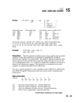
The ADSP-2101, ADSP-2105, ADSP-2115, and ADSP-2111 processors operate
with an input clock frequency equal to the instruction cycle rate. The
ADSP-2171, ADSP-2181, and ADSP-21msp58/59 processors operate with an
input clock frequency equal to half the instruction rate; for example, a
16.67 MHz input clock produces a 33 MHz instruction rate (30 ns cycle time).
Device timing is relative to the internal clock rate which is indicated by the
CLKOUT signal.
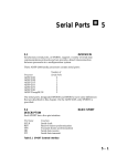
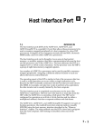
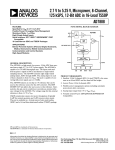
Because these processors include an on-chip oscillator circuit, an external
crystal can be used. The crystal should be connected between the CLKIN and
XTAL pins, with two capacitors connected as shown in Figure 9.1, which can
be found on the following page. A parallel-resonant, fundamental frequency,
microprocessor-grade crystal should be used. The frequency value selected
for the crystal should be equal to the desired instruction rate for the processor
(for the ADSP-2101, ADSP-2105, ADSP-2115, and ADSP-2111) or half the
desired instruction rate (for the ADSP-2171, ADSP-2181, and
ADSP-21msp58/59).
9–1
9 System Interface
CLKIN
XTAL
CLKOUT
ADSP-21xx
Figure 9.1 External Crystal Connections
The internal phased lock loop of the processors generates an internal
clock which is four times the instruction rate.
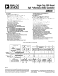
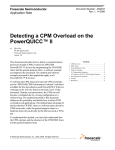
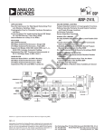
The processors also generate a CLKOUT signal which is synchronized to
the processors’ internal cycles and operates at the instruction cycle rate. A
phase-locked loop is used to generate CLKOUT and to divide each
instruction cycle into a sequence of internal time periods called processor
states. The relationship between the phases of CLKIN, CLKOUT, and the
processor states is shown in Figure 9.2 for the ADSP-2101, ADSP-2105,
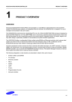
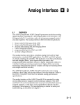
ADSP-2115, and ADSP-2111 processors. Figure 9.3 shows the same
information for the ADSP-2171, ADSP-2181, and ADSP-21msp58/59
processors. The phases of the internal processor clock are dependent upon
the period of the external clock.
The CLKOUT output can be disabled on the ADSP-2171, ADSP-2181, and
ADSP-21msp58/59 processors. This is controlled by the CLKODIS bit in
the SPORT0 Autobuffer Control Register.
CLKIN
3
INTERNAL
PROCESSOR
STATE
4
1
2
3
4
PROCESSOR
CYCLE
CLKOUT
Figure 9.2 Clock Signals & Processor States (ADSP-2101, ADSP-2105, ADSP-2115, ADSP2111)
9–2
System Interface 9
CLKIN
4
INTERNAL
PROCESSOR
STATE
1
2
3
PROCESSOR
CYCLE
4
1
2
3
4
PROCESSOR
CYCLE
CLKOUT
Figure 9.3 Clock Signals & Processor States (ADSP-2171, ADSP-2181, ADSP-21msp58/59)
9.2.1
Synchronization Delay
Each processor has several asynchronous inputs (interrupt requests, for
example), which can be asserted in arbitrary phase to the processor clock.
The processor synchronizes such signals before recognizing them. The
delay associated with signal recognition is called synchronization delay.
Different asynchronous inputs are recognized at different points in the
processor cycle. Any asynchronous input must be valid prior to the
recognition point to be recognized in a particular cycle. If an input does
not meet the setup time on a given cycle, it is recognized either in the
current cycle or during the next cycle if it remains valid.
Edge-sensitive interrupt requests are latched internally so that the request
signal only has to meet the pulse width requirement. To ensure the
recognition of any asynchronous input, however, the input must be
asserted for at least one full processor cycle plus setup and hold time.
Setup and hold times are specified in the data sheet for each individual
device.
9.2.2
1x & 1/2x Clock Considerations
Each processor requires only a 1X or 1/2X frequency clock signal. They
use what is effectively an on-chip phase-locked loop to generate the higher
frequency internal clock signals and CLKOUT. Because these clocks are
generated based on the rising edge of CLKIN, there is no ambiguity about
the phase relationship of two processors sharing the same input clock.
Multiple processor synchronization is simplified as a result.
9–3
9 System Interface
Using a 1X or 1/2X frequency input clock with the phase-locked loop to
generate the various internal clocks imposes certain restrictions. The CLKIN
signal must be valid long enough to achieve phase lock before RESET can be
deasserted. Also, the clock frequency cannot be changed unless the processor
is in RESET. Refer to the processor data sheets for details.
9.3
RESET
RESET halts execution and causes a hardware reset of the processor. The
RESET signal must be asserted when the processor is powered up to assure
proper initialization.
Tables 9.2–9.7 show the RESET state of various registers, including the
processors’ on-chip memory-mapped status/control registers. The values of
any registers not listed are undefined at reset. The contents of on-chip
memory are unchanged after RESET, except as shown in Tables 9.2–9.7 for
the data-memory-mapped control/status registers. The CLKOUT signal
continues to be generated by the processor during RESET, except when
disabled on the ADSP-2171, ADSP-2181, or ADSP-21msp58/59.
The contents of the computation unit (ALU, MAC, Shifter) and data address
generator (DAG1, DAG2) registers are undefined following RESET.
When RESET is released, the processor’s booting operation takes place,
depending on the state of the processor’s MMAP pin. Program booting is
described in Chapter 10, “Memory Interface.”
For the ADSP-2111, ADSP-2171, and ADSP-21msp58/59 processors, which
include a host interface port, setting the software reset bit in the HSR7
register has the same affect as asserting RESET. This allows either the host
processor or the ADSP-21xx to initiate a reset under software control.
In a multiprocessing system with several processors, a synchronous RESET is
required.
9.4
FORCED REBOOTING
SOFTWARE-
Software-forced reboots can be accomplished in several ways. A softwareforced reboot clears the context of the processor and initializes some
registers. A context clear clears the processor stacks and restart execution at
address 0x0000. Table 9.1 shows the different ways each processor can
perform a software reboot.
9–4
System Interface 9
Processor
ADSP-2101
ADSP-2105
ADSP-2111
ADSP-2115
Reboot Method
Boot Force
Description
Setting the BFORCE bit in the System
Control Register causes a reboot
ADSP-2171
Boot Force
Setting the BFORCE bit in the System
Control Register causes a reboot
Powerup Context Reset
Setting the PUCR bit in the SPORT1
Autobuffer & Powerdown Control
Register causes a reboot on recovery
from powerdown
BDMA Context Reset
Setting the BCR bit in the BDMA
Control Register before writing to the
BDMA Word Count Register
(BWCOUNT) causes a reboot.
Execution starts after the BDMA reboot
is completed.
Powerup Context Reset
Setting the PUCR bit in the SPORT1
Autobuffer & Powerdown Control
Register causes a reboot on recovery
from powerdown
ADSP-2181
Table 9.1 Software-Forced Rebooting
Tables 9.2–9.7 show the state of the processor registers after a softwareforced reboot. The values of any registers not listed are unchanged by a
reboot.
During booting (and rebooting), all interrupts including serial port
interrupts are masked and autobuffering is disabled. The serial port(s)
remain active; one transfer—from internal shift register to data register—
can occur for each serial port before there are overrun problems.
The timer runs during a reboot. If a timer interrupt occurs during the
reboot, it is masked. Thus, if more than one timer interrupt occurs during
the reboot, the processor latches only the first. A timer overrun can occur.
9–5
9 System Interface
Control Field
Description
Reset
Reboot
Bus Exchange Register
PX
PX register
undefined
undefined
Status Registers
IMASK
ASTAT
MSTAT
SSTAT
ICNTL
IFC
Interrupt service enables
Arithmetic status
Mode status
Stack status
Interrupt control
Interrupt force/clear
0
0
0
0x55
undefined
0
0
0
unchanged
0x55
unchanged
0
Control Registers (memory-mapped)
BWAIT
Boot memory wait states
BPAGE
Boot page
SPORT1 configure
Configuration
SPE0
SPORT0 enable
SPE1
SPORT1 enable
DWAIT0–4
Data memory wait states
PWAIT
Program memory wait
TCOUNT
Timer count register
TPERIOD
Timer period register
TSCALE
Timer scale register
3
0
1
0
0
7
7
undefined
undefined
undefined
unchanged
unchanged
unchanged
unchanged
unchanged
unchanged
unchanged
operates during reboot
unchanged
unchanged
Serial Port Control Registers (memory-mapped, one set per SPORT)
ISCLK
Internal serial clock
0
RFSR, TFSR
Frame sync required
0
RFSW, TFSW
Frame sync width
0
IRFS, ITFS
Internal frame sync
0
INVRFS, INVTFS
Invert frame sense
0
DTYPE
Companding type, format
0
SLEN
Serial word length
0
SCLKDIV
Serial clock divide
undefined
RFSDIV
RFS divide
undefined
Multichannel word enable bits
undefined
MCE
Multichannel enable
0
MCL
Multichannel length
0
MFD
Multichannel frame delay
0
INVTDV
Invert transmit data valid
0
RBUF, TBUF
Autobuffering enable
0
TIREG, RIREG
Autobuffer I index
undefined
TMREG, RMREG
Autobuffer M index
undefined
unchanged
unchanged
unchanged
unchanged
unchanged
unchanged
unchanged
unchanged
unchanged
unchanged
unchanged
unchanged
unchanged
unchanged
0
unchanged
unchanged
FO (SPORT1 only)
unchanged
Flag Out value
undefined
Table 9.2 ADSP-2101/ADSP-2115 State After Reset Or Software Reboot
9–6
System Interface 9
Control Field
Description
Reset
Reboot
Bus Exchange Register
PX
PX register
undefined
undefined
Status Registers
IMASK
ASTAT
MSTAT
SSTAT
ICNTL
IFC
Interrupt service enables
Arithmetic status
Mode status
Stack status
Interrupt control
Interrupt force/clear
0
0
0
0x55
undefined
0
0
0
unchanged
0x55
unchanged
0
Control Registers (memory-mapped)
BWAIT
Boot memory wait states
BPAGE
Boot page
SPORT1 configure
Configuration
SPE1
SPORT1 enable
DWAIT0–4
Data memory wait states
PWAIT
Program memory wait
TCOUNT
Timer count register
TPERIOD
Timer period register
TSCALE
Timer scale register
3
0
1
0
7
7
undefined
undefined
undefined
unchanged
unchanged
unchanged
unchanged
unchanged
unchanged
operates during reboot
unchanged
unchanged
Serial Port 1 Control Registers (memory-mapped)
ISCLK
Internal serial clock
RFSR, TFSR
Frame sync required
RFSW, TFSW
Frame sync width
IRFS, ITFS
Internal frame sync
INVRFS, INVTFS
Invert frame sense
DTYPE
Companding type, format
SLEN
Serial word length
SCLKDIV
Serial clock divide
RFSDIV
RFS divide
RBUF, TBUF
Autobuffering enable
TIREG, RIREG
Autobuffer I index
TMREG, RMREG
Autobuffer M index
0
0
0
0
0
0
0
undefined
undefined
0
undefined
undefined
unchanged
unchanged
unchanged
unchanged
unchanged
unchanged
unchanged
unchanged
unchanged
0
unchanged
unchanged
FO
undefined
unchanged
Flag Out value
Table 9.3 ADSP-2105 State After Reset Or Software Reboot
9–7
9 System Interface
Control Field
Description
Reset
Reboot
Bus Exchange Register
PX
PX register
undefined
undefined
Status Registers
IMASK
ASTAT
MSTAT
SSTAT
ICNTL
IFC
Interrupt service enables
Arithmetic status
Mode status
Stack status
Interrupt control
Interrupt force/clear
0
0
0
0x55
undefined
0
0
0
unchanged
0x55
unchanged
0
Control Registers (memory-mapped)
BWAIT
Boot memory wait states
BPAGE
Boot page
SPORT1 configure
Configuration
SPE0
SPORT0 enable
SPE1
SPORT1 enable
DWAIT0–4
Data memory wait states
PWAIT
Program memory wait
TCOUNT
Timer count register
TPERIOD
Timer period register
TSCALE
Timer scale register
3
0
1
0
0
7
7
undefined
undefined
undefined
unchanged
unchanged
unchanged
unchanged
unchanged
unchanged
unchanged
operates during reboot
unchanged
unchanged
Serial Port Control Registers (memory-mapped, one set per SPORT)
ISCLK
Internal serial clock
0
RFSR, TFSR
Frame sync required
0
RFSW, TFSW
Frame sync width
0
IRFS, ITFS
Internal frame sync
0
INVRFS, INVTFS
Invert frame sense
0
DTYPE
Companding type, format
0
SLEN
Serial word length
0
SCLKDIV
Serial clock divide
undefined
RFSDIV
RFS divide
undefined
Multichannel word enable bits
undefined
MCE
Multichannel enable
0
MCL
Multichannel length
0
MFD
Multichannel frame delay
0
INVTDV
Invert transmit data valid
0
RBUF, TBUF
Autobuffering enable
0
TIREG, RIREG
Autobuffer I index
undefined
TMREG, RMREG
Autobuffer M index
undefined
unchanged
unchanged
unchanged
unchanged
unchanged
unchanged
unchanged
unchanged
unchanged
unchanged
unchanged
unchanged
unchanged
unchanged
0
unchanged
unchanged
FO (SPORT1 only)
undefined
unchanged
undefined
0x0000
0x0080
0
used during HIP reboot
used during HIP reboot
unchanged
unchanged
Flag Out value
Host Interface Port Registers (memory-mapped)
HDR0-5
HIP data registers
HSR6
HIP status register
HSR7
HIP status register
HMASK
HIP interrupt enables
Table 9.4 ADSP-2111 State After Reset Or Software Reboot
9–8
System Interface 9
Control Field
Description
Reset
Reboot
Bus Exchange Register
PX
PX register
undefined
undefined
Status Registers
IMASK
ASTAT
MSTAT
SSTAT
ICNTL
IFC
Interrupt service enables
Arithmetic status
Mode status
Stack status
Interrupt control
Interrupt force/clear
0
0
0
0x55
undefined
0
0
0
unchanged
0x55
unchanged
0
3
0
1
0
0
7
7
undefined
undefined
undefined
0
0
0
0
unchanged
unchanged
unchanged
unchanged
unchanged
unchanged
unchanged
operates during reboot
unchanged
unchanged
unchanged
unchanged
unchanged
unchanged
0
unchanged
Control Registers (memory-mapped)
BWAIT
Boot memory wait states
BPAGE
Boot page
SPORT1 configure
Configuration
SPE0
SPORT0 enable
SPE1
SPORT1 enable
DWAIT0–4
Data memory wait states
PWAIT
Program memory wait
TCOUNT
Timer count register
TPERIOD
Timer period register
TSCALE
Timer scale register
ROMENABLE
Program memory ROM enable
PDFORCE
Powerdown force
PUCR
Powerup context reset
XTALDIS
XTAL pindrive disable
during powerdown
XTALDELAY
Delay startup from powerdown
(4096 cycles)
Serial Port Control Registers (memory-mapped, one set per SPORT)
ISCLK
Internal serial clock
0
RFSR, TFSR
Frame sync required
0
RFSW, TFSW
Frame sync width
0
IRFS, ITFS
Internal frame sync
0
INVRFS, INVTFS
Invert frame sense
0
DTYPE
Companding type, format
0
SLEN
Serial word length
0
SCLKDIV
Serial clock divide
undefined
RFSDIV
RFS divide
undefined
Multichannel word enable bits
undefined
MCE
Multichannel enable
0
MCL
Multichannel length
0
MFD
Multichannel frame delay
0
INVTDV
Invert transmit data valid
0
RBUF, TBUF
Autobuffering enable
0
TIREG, RIREG
Autobuffer I index
undefined
TMREG, RMREG
Autobuffer M index
undefined
unchanged
unchanged
unchanged
unchanged
unchanged
unchanged
unchanged
unchanged
unchanged
unchanged
unchanged
unchanged
unchanged
unchanged
0
unchanged
unchanged
Table 9.5 ADSP-2171 State After Reset Or Software Reboot (cont. on next page)
9–9
9 System Interface
FO (SPORT1 only)
CLKODIS
BIASRND
Flag Out value
CLKOUT disable
MAC biased rounding
Host Interface Port Registers (memory-mapped)
HDR0-5
HIP data registers
HSR6
HIP status register
HSR7
HIP status register
HMASK
HIP interrupt enables
undefined
0
0
unchanged
unchanged
unchanged
undefined
0x0000
0x0080
0
used during HIP reboot
used during HIP reboot
unchanged
unchanged
Table 9.5 ADSP-2171 State After Reset Or Software Reboot
Control Field
Description
Reset
Reboot
Bus Exchange Register
PX
PX register
undefined
undefined
Status Registers
IMASK
ASTAT
MSTAT
SSTAT
ICNTL
IFC
Interrupt service enables
Arithmetic status
Mode status
Stack status
Interrupt control
Interrupt force/clear
0
0
0
0x55
undefined
0
0
0
unchanged
0x55
unchanged
0
3
0
1
0
0
7
7
undefined
undefined
undefined
0
0
0
unchanged
unchanged
unchanged
unchanged
unchanged
unchanged
unchanged
operates during reboot
unchanged
unchanged
unchanged
unchanged
unchanged
0
unchanged
Control Registers (memory-mapped)
BWAIT
Boot memory wait states
BPAGE
Boot page
SPORT1 configure
Configuration
SPE0
SPORT0 enable
SPE1
SPORT1 enable
DWAIT0–4
Data memory wait states
PWAIT
Program memory wait
TCOUNT
Timer count register
TPERIOD
Timer period register
TSCALE
Timer scale register
PDFORCE
Powerdown force
PUCR
Powerup context reset
XTALDIS
XTAL pindrive disable
during powerdown
XTALDELAY
Delay startup from powerdown
(4096 cycles)
Table 9.6 ADSP-2181 State After Reset Or Software Reboot (cont. on next page)
9 – 10
System Interface 9
Serial Port Control Registers (memory-mapped, one set per SPORT)
ISCLK
Internal serial clock
RFSR, TFSR
Frame sync required
RFSW, TFSW
Frame sync width
IRFS, ITFS
Internal frame sync
INVRFS, INVTFS
Invert frame sense
DTYPE
Companding type, format
SLEN
Serial word length
SCLKDIV
Serial clock divide
RFSDIV
RFS divide
Multichannel word enable bits
MCE
Multichannel enable
MCL
Multichannel length
MFD
Multichannel frame delay
INVTDV
Invert transmit data valid
RBUF, TBUF
Autobuffering enable
TIREG, RIREG
Autobuffer I index
TMREG, RMREG
Autobuffer M index
0
0
0
0
0
0
0
undefined
undefined
undefined
0
0
0
0
0
undefined
undefined
unchanged
unchanged
unchanged
unchanged
unchanged
unchanged
unchanged
unchanged
unchanged
unchanged
unchanged
unchanged
unchanged
unchanged
0
unchanged
unchanged
FO (SPORT1 only)
CLKODIS
BIASRND
undefined
0
0
unchanged
unchanged
unchanged
Flag Out value
CLKOUT disable
MAC biased rounding
External Memory Control Registers (non-memory-mapped)
DMOVLAY
Data memory overlay select
PMOVLAY
Program memory overlay select
(memory-mapped)
DWAIT
Data memory overlay wait states
PWAIT
Program memory overlay wait states
BMWAIT
Byte memory wait states
IOWAIT0-3
I/O memory wait states
CMSSEL
Composite memory select
0
0
unchanged
unchanged
0x7
0x7
0x7
0x7
0xB
unchanged
unchanged
unchanged
unchanged
unchanged
Programmable Flag Data & Control Registers (memory-mapped)
PFDATA
Programmable flag data
PFTYPE
Programmable flag direction
undefined
0
unchanged
unchanged
DMA Control Registers (memory-mapped)
IDMAA
IDMA Internal Memory Address
IDMAD
IDMA Destination Memory Type
BIAD
BDMA Internal Memory Address
BEAD
BDMA External Memory Address
BTYPE
BDMA Transfer Word Type
BDIR
BDMA Transfer Direction
BCR
BDMA Context Reset
BWCOUNT
BDMA Word Count
BMPAGE
External Byte Memory Page
0x00
0
0
0
0
0
1
0x20
0
unchanged
unchanged
0x20*
0x60*
unchanged
unchanged
unchanged
0*
0*
Table 9.6 ADSP-2181 State After Reset Or Software Reboot
* These values assume that you have just completed an initial BDMA boot load of the
ADSP-2181 (MMAP=0 & BMODE=0). For more information on BDMA register contents
during the boot loading process see Table 9.8. These values will vary with a processor
reboot (other than initial load), since they depend on the previous values.
9 – 11
9 System Interface
Control Field
Description
Reset
Reboot
Bus Exchange Register
PX
PX register
undefined
undefined
Status Registers
IMASK
ASTAT
MSTAT
SSTAT
ICNTL
IFC
Interrupt service enables
Arithmetic status
Mode status
Stack status
Interrupt control
Interrupt force/clear
0
0
0
0x55
undefined
0
0
0
unchanged
0x55
unchanged
0
3
0
1
0
0
7
7
undefined
undefined
undefined
0
0
0
0
unchanged
unchanged
unchanged
unchanged
unchanged
unchanged
unchanged
operates during reboot
unchanged
unchanged
unchanged
unchanged
unchanged
unchanged
0
unchanged
0
0
0
0
0
0
0
undefined
undefined
undefined
0
0
0
0
0
undefined
undefined
unchanged
unchanged
unchanged
unchanged
unchanged
unchanged
unchanged
unchanged
unchanged
unchanged
unchanged
unchanged
unchanged
unchanged
0
unchanged
unchanged
Control Registers (memory-mapped)
BWAIT
Boot memory wait states
BPAGE
Boot page
SPORT1 configure
Configuration
SPE0
SPORT0 enable
SPE1
SPORT1 enable
DWAIT0–4
Data memory wait states
PWAIT
Program memory wait
TCOUNT
Timer count register
TPERIOD
Timer period register
TSCALE
Timer scale register
ROMENABLE
Program memory ROM enable
PDFORCE
Powerdown force
PUCR
Powerup context reset
XTALDIS
XTAL pindrive disable
during powerdown
XTALDELAY
Delay startup from powerdown
(4096 cycles)
Serial Port Control Registers (memory-mapped, one set per SPORT)
ISCLK
Internal serial clock
RFSR, TFSR
Frame sync required
RFSW, TFSW
Frame sync width
IRFS, ITFS
Internal frame sync
INVRFS, INVTFS
Invert frame sense
DTYPE
Companding type, format
SLEN
Serial word length
SCLKDIV
Serial clock divide
RFSDIV
RFS divide
Multichannel word enable bits
MCE
Multichannel enable
MCL
Multichannel length
MFD
Multichannel frame delay
INVTDV
Invert transmit data valid
RBUF, TBUF
Autobuffering enable
TIREG, RIREG
Autobuffer I index
TMREG, RMREG
Autobuffer M index
Table 9.7 ADSP-21msp58/59 State After Reset Or Software Reboot (cont. on next page)
9 – 12
System Interface 9
FO (SPORT1 only)
CLKODIS
BIASRND
Flag Out value
CLKOUT disable
MAC biased rounding
undefined
0
0
unchanged
unchanged
unchanged
Host Interface Port Registers (memory-mapped)
HDR0-5
HIP data registers
HSR6
HIP status register
HSR7
HIP status register
HMASK
HIP interrupt enables
undefined
0x0000
0x0080
0
used during HIP reboot
used during HIP reboot
unchanged
unchanged
Analog Autobuffer/Powerdown Registers
ARBUF
Receive autobuffer enable
ATBUF
Transmit autobuffer enable
control bits
Analog autobuffer control bits
0
0
0
0
0
unchanged
Table 9.7 ADSP-21msp58/59 State After Reset Or Software Reboot
9.4.1
ADSP-2181 Register Values for BDMA Booting
The state of some ADSP-2181 registers during reset and rebooting is
influenced by the MMAP and BMODE pins. If these pins are set for a BDMA
boot, the values in the BDMA registers change as shown in Table 9.8.
Register
BIAD
BEAD
BTYPE
BDIR
BMPAGE
BWCOUNT
BMWAIT
BCR
Process Description*
BDMA Internal Memory Address.
Set for internal address 0.
BDMA External Memory Address.
Set for external address 0.
BDMA Transfer Word Type.
Set for 24-bit program memory words.
BDMA Transfer Direction.
Set to transfer data from byte memory.
BDMA Page Selection.
Set to byte memory page 0.
BDMA Word Count.
Set to transfer 32 words.
BDMA Port Wait States.
Set to 7 waits per transfer.
BDMA Context Reset. **
Value Before Boot
0
Value After Boot
0x20
0
0x60
0
0
0
0
0
0
0x20
0
0x7
0x7
1
1
Table 9.8 BDMA Registers Before And After Initial Boot Loading
* Assuming MMAP=0 and BMODE=0 for a BDMA boot.
** Set to 1 to (a) holdoff instruction execution during BDMA transfer,
(b) start execution at address PM(0x0000) after BDMA transfer, and
(c) leave a BDMA interrupt pending. This sequence of events occurs if
BCR is set before BWCOUNT is written, or after the initial boot.
9 – 13
9 System Interface
9.5
INTERRUPTS
EXTERNAL
Each ADSP-2100 family processor has a number of prioritized, individually
maskable external interrupts which can be either level- or edge-triggered.
These interrupt request pins are named IRQ0, IRQ1, and IRQ2. The IRQ0 and
IRQ1 pins are only available as the (optional) alternate configuration of
SPORT1. The configuration of SPORT1 as either a serial port or as interrupts
(and flags) is determined by bit 10 of the processor’s system control register.
The ADSP-2181 processor additionally has two dedicated level-triggered
interrupt request pins and one dedicated edge-triggered interrupt request pin;
these are IRQL0 , IRQL1, and IRQE.
Internal interrupts, including serial port, timer, host interface port, DMA and
analog interface interrupts, are discussed in other chapters. Additional
information about interrupt masking, set up, and operation can be found in
Chapter 3, “Program Control.”
9.5.1
Interrupt Sensitivity
Individual external interrupts can be configured in the ICNTL register as
either level-sensitive or edge-sensitive.
Level-sensitive interrupts operate by asserting the interrupt request line
(IRQx) until the request is recognized by the processor. Once recognized, the
request must be deasserted before unmasking the interrupt so that the DSP
does not continually respond to the interrupt.
In contrast, edge-triggered interrupt requests are latched when any high-tolow transition occurs on the interrupt line. The processor latches the interrupt
so that the request line may be held at any level for an arbitrarily long period
between interrupts. This latch is automatically cleared when the interrupt is
serviced. Edge-triggered interrupts require less external hardware than levelsensitive requests since there is never a need to hold or negate the request.
With level-sensitive interrupts, however, many interrupting devices can share
a single request input; this allows easy system expansion.
An interrupt request will be serviced if it is not masked (in the IMASK
register) and a higher priority request is not pending. Valid requests initiate
an interrupt servicing sequence that vectors the processor to the appropriate
interrupt vector address. The interrupt vector addresses for each family
processor are given in Appendix D. There is a synchronization delay
9 – 14
System Interface 9
associated with both external interrupt request lines and internal interrupts.
If an interrupt occurs during a waitstated external memory access or during the
extra cycles required to execute an instruction that accesses external memory
more than once, it is not recognized between the cycles, only before or after.
Edge-sensitive interrupts are latched, but not serviced, during bus grant (BG)
unless the GO mode is enabled.
In order to service an interrupt, the processor must be running and executing
instructions. The IDLE instruction can be used to effectively halt processor
operations while waiting for an interrupt.
Edge-sensitive and level-sensitive interrupt requests are serviced similarly.
Edge-sensitive interrupts may remain active (low) indefinitely, while levelsensitive interrupts must be deasserted before the RTI instruction is executed;
otherwise, the same interrupt immediately recurs.
Care must be taken with the serial port (SPORT1) that can be configured for
alternate functions (IRQ0 and IRQ1). If the RFS1 or TFS1 input is held low
when SPORT1 is configured as the serial port and then is reconfigured as IRQ0
and IRQ1, an interrupt request can be generated. This interrupt request can be
cleared with the use of the IFC register.
9.6
FLAG PINS
All ADSP-21xx processors provide flag pins. The alternate configuration of
SPORT1 includes a Flag In (FI) pin and a Flag Out (FO) pin. The configuration
of SPORT1 as either a serial port or as flags and interrupts is selected by bit 10
of the processor’s system control register.
FI can be used to control program branching, using the IF FLAG_IN and IF
NOT FLAG_IN conditions of the JUMP and CALL instructions. These
conditions are evaluated based on the last state of the FI pin; FLAG_IN is true if
FI was last sampled as a 1 and false if last sampled as a 0. FO can be used as a
general purpose external signal. The state of FO is also available as a read-only
bit of the SPORT1 control register.
The ADSP-2111, ADSP-2171, ADSP-2181, and ADSP-21msp58/59 processors
have three additional flag output pins: FL0, FL1 and FL2. These flags (and FO)
can be controlled in software to signal events or conditions to any external
device such as a host processor. The Modify Flag Out instruction, which is
conditional, can perform SET, RESET and TOGGLE actions—this instruction
allows programs executing on the DSP processor to control the state of its flag
output pins. Note that if the condition in the Modify Flag Out instruction is CE
9 – 15
9 System Interface
(counter expired), the counter is not decremented as in other IF CE
instructions.
Flag outputs FL0, FL1 and FL2 are set to 1 at RESET. The Flag Out (F0) is
not affected by RESET.
The ADSP-2181 has eight additional general-purpose flag pins, PF7-0.
These flags can be programmed as either inputs or outputs; they default to
inputs following reset. The PFx pins are programmed with the use of two
memory-mapped registers. The Programmable Flag & Composite Select
Control Register determines the flag direction: 1=output and 0=input. The
Programmable Flag Data Register is used to read and write the values on
the pins. Data being read from a pin configured as an input is
synchronized to the processor’s clock. Pins configured as outputs drive
the appropriate output value. When the PFDATA register is read, any
pins configured as outputs will read back the value being driven out.
Programmable Flag & Composite Select Control
15
14
13
12
0
1
1
1
BMWAIT
CMSSEL
1 = Enable CMS
0 = Disable CMS
11
10
9
8
7
6
5
4
3
2
1
0
0
0
0
0
0
0
0
0
1
0
1
1
IOM
BM
DM
PM
DM(0x3FE6)
PFTYPE
1 = Output
0 = Input
Figure 9.4 Programmable Flag & Composite Select Control Register (ADSP2181)
9 – 16
System Interface 9
Programmable Flag Data
15
14
13
12
11
10
9
8
7
6
5
4
3
2
1
0
DM(0x3FE5)
PFDATA
Figure 9.5 Programmable Flag Data Register (ADSP-2181)
9.7
POWERDOWN
The ADSP-2171, ADSP-2181, and ADSP-21msp58/59 provide a
powerdown feature that allows the processor to enter a very low power
dormant state through hardware or software control. In this CMOS
standby state, power consumption is less than 1 mW (approximate). (Refer
to the processor data sheet for exact power consumption specifications.)
The powerdown feature is useful for applications where power
conservation is necessary, for example in battery-powered operation.
Features of powerdown include:
• Internal clocks are disabled
• Processor registers and memory contents are maintained
• Ability to recover from powerdown in less than 100 CLKIN cycles
• Ability to disable internal oscillator when using crystal
• No need to shut down clock for lowest power when using external
oscillator
• Interrupt support for executing “housekeeping” code before entering
powerdown and after recovering from powerdown
• User selectable powerup context
9 – 17
9 System Interface
Even though the processor is put into the powerdown mode, the lowest
level of power consumption still might not be achieved if certain
guidelines are not followed. Lowest possible power consumption requires
no additional current flow through processor output pins and no
switching activity on active input pins. Therefore, a careful analysis of pin
loading in your circuit is required. The following sections detail the
proper powerdown procedure as well as provide guidelines for clock and
output pin connections required for optimum low-power performance.
9.7.1
Powerdown Control
You can control several parameters of powerdown operation through
control bits in the SPORT1 Autobuffer/Powerdown Control Register
(or Analog Autobuffer/Powerdown Control Register on the
ADSP-21msp58/59). This control register is memory-mapped at location
0x3FEF and is shown in Figure 9.6.
SPORT1 Autobuffer / Powerdown Control Register
15
14
13
12
11
10
9
8
7
6
5
4
3
2
1
0
DM(0x3FEF)
XTALDIS
XTAL Pin Drive Disable During Powerdown
1=disabled, 0=enabled
(XTAL pin should be disabled when
no external crystal is connected)
XTALDELAY
Delay Startup From Powerdown 4096 Cycles
1=delay, 0=no delay
(use delay to allow internal phase locked
loop or external oscillator to stabilize)
PDFORCE
Powerdown Force
1=force processor to vector to
powerdown interrupt
PUCR
Powerup Context Reset
1=soft reset (clear context)*,
0=resume execution
Figure 9.6 SPORT1 Autobuffer / Powerdown Control Register
* PUCR=1: Clears the PC, STATUS, LOOP and CNTR stacks. IMASK and ASTAT
registers are cleared to 0 and SSTAT is set to 0x55. The processor will start executing
instructions from address 0x0000.
9 – 18
System Interface 9
9.7.2
Entering Powerdown
The powerdown sequence is defined as follows.
1.) Initiate the powerdown sequence by applying a high-to-low transition
to the PWD pin or by setting the powerdown force control bit
(PDFORCE) in the SPORT1 Autobuffer/Powerdown Control Register.
2.) The processor vectors to the non-maskable powerdown interrupt
vector at address 0x002C. (Note: The powerdown interrupt is never
masked. You must be careful not to cause multiple powerdown
interrupts to occur or stack overflow may result. Multiple powerdown
interrupts can occur if the PWD input is pulsed while the processor is
already servicing the powerdown interrupt.)
3.) Any number of housekeeping instructions, starting at location 0x002C,
can be executed prior to the processor entering the powerdown mode.
Typically, this section of code is used to configure the powerdown
state, disable on-chip peripherals and clear pending interrupts.
4.) The processor now enters powerdown mode when it executes an IDLE
instruction (while PWD is asserted). The processor may take either one
or two cycles to power down depending upon internal clock states
during the execution of the IDLE instruction. All register and memory
contents are maintained while in powerdown. Also, all active outputs
are held in whatever state they are in before going into powerdown.
If an RTI is executed before the IDLE instruction, then the processor
returns from the powerdown interrupt and the powerdown sequence is
aborted.
While the processor is in the powerdown mode, the processor is in CMOS
standby. This allows the lowest level of power consumption where most
input pins are ignored. Active inputs need to be held at CMOS levels to
achieve lowest power. More information can be found in the section
“Operation During Powerdown” later in this chapter.
9 – 19
9 System Interface
9.7.3
Exiting Powerdown
The powerdown mode can be exited with the use of the PWD pin or with
RESET. There are also several user-selectable modes for start-up from
powerdown which specify a start-up delay as well as specify the program
flow after start-up. This allows the program to resume from where it left
off before powerdown or for the program context to be cleared.
9.7.3.1 Ending Powerdown With The PWD Pin
Applying a low-to-high transition to the PWD pin will take the processor
out of powerdown mode. You have the option of selecting the amount of
time the processor takes to come out of the powerdown mode with the
“delay start-up from powerdown” control bit (XTALDELAY, bit 14 in the
Powerdown Control Register.) If this bit is cleared to 0, no additional
delay over the quick start-up (100 cycles) is introduced. If this bit is set to
1, a delay of 4096 cycles is introduced. The delay feature is used
depending upon the state of an external clock oscillator at the time of
powerup or if the internal clock is disabled. This is further discussed in the
sections “Systems Using an External TTL/CMOS Clock” and “Systems
Using a Crystal and The Internal Oscillator.”
You can also program one of two options directing the processor how to
resume operation. The context for exiting powerdown is set by bit 12
(PUCR, powerup context reset) of the Powerdown Control Register.
If the PUCR control bit is cleared to 0, the processor will continue to
execute instructions following the IDLE instruction. For example, a highto-low transition is applied to the PWD pin which causes the processor to
vector to the powerdown interrupt routine. In this routine, a few
housekeeping tasks are performed and the IDLE instruction is executed.
The processor powers down. Some time later a low-to-high transition is
applied to the PWD pin, causing the processor to exit powerdown mode.
Since the PUCR bit is 0, the processor resumes executing instructions in
the powerdown interrupt routine, starting at the instruction following the
IDLE instruction. When an RTI instruction is encountered, control then
passes back to the main routine.
If the PUCR bit is set to 1 for a clear context, the processor resumes
operation from powerdown by clearing the PC, STATUS, LOOP and
CNTR stacks. The IMASK and ASTAT registers are set to 0 and the SSTAT
goes to 0x55. The processor will start executing instructions from address
0x0000.
9 – 20
System Interface 9
9.7.3.2 Ending Powerdown With The RESET Pin
If RESET is asserted while the processor is in the powerdown mode, the
processor is reset and instructions are executed from address 0x0000. A
boot is performed if the MMAP pin is set to 0. If the RESET pin is used to
exit powerdown, then it must be held low for the appropriate number of
cycles. If the clock is stopped at powerup or operating at a different
frequency at powerup than it was before powerdown, RESET must be
held long enough for the oscillator to stabilize plus an additional 1000
CLKIN cycles for the phase locked loop to lock. The time required for the
oscillator to stabilize depends upon the type of crystal used and
capacitance of the external crystal circuit. Typically 2000 CLKIN cycles is
adequate for clock stabilization time.
If the clock was not stopped at powerup and is at a stable frequency at
powerup (same as before powerdown), only 5 cycles of RESET are
required.
When ending powerdown with RESET, the XTALDELAY (delay start-up
from powerdown) control bit is ignored.
9.7.4
Startup Time After Powerdown
The time required to exit the powerdown state depends on whether an
internal or external oscillator is used, and the method used to exit
powerdown.
9.7.4.1 Systems Using An External TTL/CMOS Clock
When the processor is in powerdown, the external clock signal is ignored
if the XTALDIS bit (XTAL pin disable) of the Powerdown Control Register
is set to 1. It is therefore not necessary to stop the external clock since no
power is wasted while the external clock is running. If the external clock is
to be stopped anyway, it must be kept running for (at least) one additional
cycle after the IDLE instruction is executed.
The XTALDIS bit should always be set before entering powerdown. This
specifies that the XTAL pin is not to be driven by the processor. During
powerdown there is no need to drive the XTAL pin when an external
oscillator is used. Disabling the XTAL pin drive during powerdown lets
the input clock run without wasting power.
After the processor is taken out of the powerdown mode by either the PWD
pin or RESET, it will begin executing instructions after a maximum startup time of 100 CLKIN cycles as long as the clock oscillator is stable and at
the same frequency as before powerdown.
9 – 21
9 System Interface
If the external clock is unstable when the processor exits powerdown, then
the XTALDELAY control bit can be used. This allows time for the external
clock to stabilize by inserting an additional 4096-cycle delay before the
processor starts to execute instructions. The start-up delay can only be used
when the processor is taken out of powerdown mode with the PWD pin.
If the processor is taken out of powerdown by RESET and the clock is stable
and at the same frequency as before powerdown, RESET needs to be held for
only 5 cycles.
9.7.4.2 Systems Using A Crystal And The Internal Oscillator
A trade-off can be made so that a fast start-up is possible, but power is
consumed by leaving the oscillator running during powerdown. If a fast
start-up is desired, then you must clear bits 14 (XTALDELAY) and 15
(XTALDIS) of the Powerdown Control Register to 0 before entering
powerdown. This selects no additional delay after start-up from powerdown
and drives the external crystal during powerdown. In this configuration, the
oscillator will continue to operate and the processor will start executing
instructions in less than 100 cycles after the low to high signal transition at
the PWD pin. The XTAL pin will also be driven and the powerdown power
consumption will be higher than the 1 mW specification. The following code
example shows the powerdown interrupt routine.
{ Sample Powerdown Code
}
{ Located at interrupt vector address 0x002C
}
pwd_int: ax0 = 0x0000; { enable crystal, no delay }
dm(0x3FEF) = ax0;
idle;
rti;
If lowest possible power consumption is required, then you must set the
XTALDELAY and XTALDIS bits to 1 before entering powerdown. This selects
the additional 4096 cycle delay to allow the oscillator to start and the phase
locked loop to lock after start-up and disables the drive to the XTAL pin
during powerdown. The following code example shows the powerdown
interrupt routine.
{ Sample Powerdown Code
}
{ Located at interrupt vector address 0x002C
}
pwd_int: ax0 = 0xC000; { disable crystal, delay }
dm(0x3FEF) = ax0;
idle;
rti;
9 – 22
System Interface 9
Depending on the particular situation and external system conditions, the
powerdown modes shown above could be set conditionally. If you want
to powerdown for a long time you may want to set the mode for lowest
power consumption. If you want to powerdown for a short time, lowest
power consumption may not be that important.
If the RESET pin is used to exit powerdown and the clock has been
stopped, then RESET must be held low for 1000 CLKIN cycles plus the
time required for the phase locked loop to lock and the crystal oscillator to
stabilize (typically 2000 CLKIN cycles.) If the clock is running during
powerdown, a RESET signal of only 5 cycles is required.
9.7.5
Processor Operation During Powerdown
Some processor circuitry may still be active during powerdown mode.
Also, some output pins remain active. A good understanding of these
states will allow you to determine the best low-power configuration for
your system. By keeping output loading and input switching to a
minimum the lowest possible power consumption can be achieved.
9.7.5.1 Interrupts And Flags
Interrupts are latched and can be serviced if the processor exits
powerdown without a context reset (PUCR=1). Any activity on the
interrupt or flag input pins during powerdown will increase the power
consumption. There should also be no resistive load on the flag output
pins (as with any active output pin) if lowest power is desired.
9.7.5.2 SPORTS
The circuitry of the serial ports is not directly affected by powerdown. The
SPORTs are indirectly affected if an internally generated SCLK or frame
sync is required. SPORT circuitry continues to operate during
powerdown.
It is possible to clock data into or out of the serial ports during
powerdown. You must supply an external serial clock to support
operation during powerdown. No interrupts or autobuffer operations will
be serviced during powerdown. Instead, the SPORT interrupts are latched
and can be serviced if the processor exits powerdown without resetting
the processor. Data clocked into the processor will remain in the receive
(RX) registers. Autobuffer transfers will occur after the device exits
powerdown if the processor is not powered up with RESET. Note that any
SPORT activity will increase the power consumption above the 1 mW
specification.
9 – 23
9 System Interface
If an external serial clock and an external frame sync signal are supplied,
data can be clocked into the RX register or out of the TX register during
powerdown. Since the TX register can not be updated while the processor
is in powerdown, the same value is repeatedly clocked out the serial port.
Also, data in the RX register is continually overwritten since the RX
register can not be read by the processor during powerdown.
If an external serial clock is used with an internal frame sync, frame sync
signals continue to be generated during powerdown since they are
derived from the serial clock. Data bits continue to be received with the
RX register being overwritten. Since data is only transmitted when the TX
register is written, data bits are only transferred out of the processor if the
processor is put in powerdown during a serial port transfer. While the
processor is being put into powerdown, the serial port transfer in progress
is allowed to complete. Since an internally generated transmit frame sync
is used, no subsequent frame syncs are generated while in powerdown.
If internal serial clock is used, there is no SPORT activity during
powerdown; the serial clock stops.
Lowest power dissipation is achieved when active SPORT pins are not
changing during powerdown and are held at CMOS levels.
9.7.5.3 HIP During Powerdown
The circuitry of the Host Interface Port (HIP) is not directly affected by
powerdown on the ADSP-2171 and ADSP-21msp58/59. The HIP is
indirectly affected since the processor, when in powerdown, is unable to
service interrupts or read and write HIP data registers. HIP circuitry
continues to operate during powerdown.
The host can write to the HIP register during powerdown but the
processor is disabled and cannot service interrupts. Instead, HIP
interrupts are latched and can be serviced if the processor exits
powerdown without a context reset (PUCR=1).
If the HDR overwrite bit (bit 7 in HSR7) is cleared, a host acknowledge
signal will not be asserted until the processor has read data written by the
host. During powerdown, the processor is unable to read the data register
and the host acknowledge signal will not be asserted. Care must be taken
in a system where the host waits for a host acknowledge. In this case, it is
possible that the host will “hang” waiting for the acknowledge while the
DSP processor is in powerdown.
9 – 24
System Interface 9
While in powerdown, the processor can be reset by writing the HSR
software reset bit. This will produce the same results as asserting the RESET
pin for five cycles (minimum RESET pulse) on the processor. If an external
crystal is used and the clock has been stopped, this reset duration is too
short; therefore software reset cannot be used in this mode. Note that any
HIP activity will increase the power consumption above the 1 mW
specification.
Two mode pins, HMD0 and HMD1, are used to put the processor’s HIP into
one of four possible modes. When HMD0 = 1, the HIP data bus is
multiplexed for both address and data. In this case, the HIP data bus inputs
are active during powerdown and any bus activity will result in higher
power dissipation. Also, inputs must be at CMOS levels. If this host mode is
used and there is potential for the bus to be floating, pull-up resistors
should be used on the data lines. If you desire the host to communicate with
other devices on the bus while the DSP processor is in powerdown, HMD0
should be held low to avoid extra power to be dissipated. When the HIP is
put in other modes where data inputs are not active this is not a problem.
Lowest power dissipation is achieved when the HIP pins are not changing
during powerdown and are held at CMOS levels.
9.7.5.4 IDMA Port During Powerdown (ADSP-2181)
The IDMA port can receive data during powerdown, but it can not respond
with an acknowledge (IACK) signal or increment the IDMA internal
address. If you are using a short read or short write and are in the middle of
an IDMA transfer, you can complete a single read or write while the
processor is in powerdown. If you are using the long read or long write
method and are in the middle of an IDMA transfer, your host must be able
to handle a “timeout” condition, as the DSP will not return an acknowledge
to the transfer in process.
Note that IDMA activity while the DSP is in powerdown uses power and
should be avoided to conserve power. For more information on lowest
power use, see “Conditions For Lowest Power Consumption.”
9 – 25
9 System Interface
9.7.5.5 BDMA Port During Powerdown (ADSP-2181)
Do not powerdown the ADSP-2181 during a BDMA transfer. If you do, the
DSP will not be able to recover correctly from powerdown and the contents of
memory accessed by the ADSP-2181’s BDMA port will be corrupted.
If you need to go into powerdown mode, either:
• Verify that the BWCOUNT register contains a zero. If a BDMA transfer is in
process, poll the BWCOUNT register to determine when the transfer is done.
or
• Abort any BDMA transfer in progress by writing 1 to the BWCOUNT
register and go into powerdown when the BWCOUNT register contains a
zero. (Note that the BDMA transfer is not properly completed in this case.)
9.7.5.6 Analog Interface (ADSP-21msp5x)
You must powerdown the ADSP-21msp58/59’s analog interface separately
from the processor, as described in the Analog Interface chapter of this manual.
The analog interface does not work during powerdown and causes additional
power to be dissipated if it is not disabled. The following code example shows
a powerdown interrupt routine for the ADSP-21msp58/59:
{ Sample Powerdown Code
{ located at address 0x002C
pwd_int: ax0 = 0x0000;
dm(0x3FEE) = ax0;
ax0 = 0x0000;
dm(0x3FEF) = ax0;
NOP;
idle;
rti;
}
}
{powerdown analog interface}
{enable crystal, no delay}
It takes three cycles for the analog interface to powerdown. The IDLE
instruction should not be executed before these three cycles have elapsed.
9.7.6
Conditions For Lowest Power Consumption
The state of all processor pins during powerdown is shown in Table 9.9.
To assure the lowest power consumption, all active input pins should be held
at a CMOS level. All active output pins should be free of resistive load since
9 – 26
System Interface 9
load current will increase power dissipation. Some pins will be in one of
several states depending upon the connection of mode pins. For example,
the ADSP-2171’s HIP data bus pins may be either active or inactive
depending whether a host write is in progress or how the host mode pins
are connected. You must perform a careful analysis of each input and
output pin in order to insure lowest power dissipation.
Some inputs are active but ignored. The state of these inputs does not
matter as long as they are at a CMOS level.
Pin
Direction
State During Powerdown
RESET
PWD
IRQ2
IRQE
IRQL0
IRQL1
MMAP
BR
BG
CLKIN
CLKOUT
XTAL
PWDACK
I
I
I
I
I
I
I
I
O
I
O
O
O
Active
Active
Active, latched but not serviced
(ADSP-2181) Active, latched but not serviced
(ADSP-2181) Active, latched but not serviced
(ADSP-2181) Active, latched but not serviced
Active
Active, no response until after powerdown
Driven HIGH unless bus is granted
Input buffer inactive, but XTAL oscillator is active unless XTALDIS bit is set
Driven HIGH
Driven HIGH if XTALDIS set, inversion of CLKIN otherwise
Driven HIGH
PMS
DMS
BMS
IOMS
CMS
RD
WR
ADDR<13:0>
DATA<23:0>
DATA<23:0>
O
O
O
O
O
O
O
O
I
O
Driven HIGH, high impedance if bus granted
Driven HIGH, high impedance if bus granted
Driven HIGH, high impedance if bus granted
(ADSP-2181) Driven HIGH, high impedance if bus granted
(ADSP-2181) Driven HIGH, high impedance if bus granted
Driven HIGH, high impedance if bus granted
Driven HIGH, high impedance if bus granted
High impedance
Inactive
High impedance
SCLK0
SCLK0
TFS0
TFS0
I
O
I
O
RFS0
RFS0
I
O
DR0
DT0
I
O
Active
Driven to static level if internal, high impedance otherwise
Active if SPORT 0 is enabled
Driven if configured internal or in multichannel mode and SPORT 0
enabled, high impedance otherwise
Active if SPORT 0 is enabled
Driven if configured internal and SPORT 0 enabled, high impedance
otherwise
Active if SPORT 0 is enabled
Driven if serial port operating. Output may be static or changing depending
upon serial clock, high impedance otherwise
Table 9.9 Pin States During Powerdown (cont. on next page)
9 – 27
9 System Interface
Pin
Direction
State During Powerdown
SCLK1
SCLK1
TFS1/IRQ1
TFS1
I
O
I
O
Active
Driven to a static level if internal, high impedance otherwise
Active if SPORT 1 is enabled or configured alternate (IRQ1)
Driven if SPORT 1 is enabled and configured for internal transmit framing,
high impedance otherwise
Active if SPORT 1 is enabled or configured alternate (IRQ0)
Driven if SPORT 1 is enabled and configured for internal receive framing,
high impedance otherwise
Active if SPORT 1 is enabled or configured alternate (FLAGIN)
Driven if serial port operating. Output may be static or changing depending
upon serial clock. Driven if SPORT 1 is enabled or configured alternate
(FLAGOUT)
RFS1/IRQ0
RFS1
I
O
DR1/FLAGIN
DT1/FLAGOUT
I
O
FL<2:0>
PF<7:0>
O
I/O
Driven to previous value
(ADSP-2181) Active
BMODE
I
Active
IRD
IWR
IS
IAL
IAD
IACK
I
I
I
I
I/O
O
(ADSP-2181) Active, if IS asserted
(ADSP-2181) Active, if IS asserted
(ADSP-2181) Active
(ADSP-2181) Active, if IS asserted
(ADSP-2181) Active, if an operation in progress
(ADSP-2181) Active
HSIZE
HMD0
HMD1
HSEL
HRD
HWR
HADR<2:0>
HDATA<15:0>
I
I
I
I
I
I
I
I
HDATA<15:0>
HACK
VIN (NORM)
VIN (AUX)
VFB (NORM)
VFB (AUX)
VOUTP
VOUTN
VREF
O
O
I
I
O
O
O
O
O
(ADSP-2171, ADSP-21msp5x) Active
(ADSP-2171, ADSP-21msp5x) Active
(ADSP-2171, ADSP-21msp5x) Active
(ADSP-2171, ADSP-21msp5x) Active
(ADSP-2171, ADSP-21msp5x) Active
(ADSP-2171, ADSP-21msp5x) Active
(ADSP-2171, ADSP-21msp5x) Active
(ADSP-2171, ADSP-21msp5x) Active if host writing or HMD1 and
HA2/HALE HIGH, inactive otherwise
(ADSP-2171, ADSP-21msp5x) Driven if host reading, high impedance otherwise
(ADSP-2171, ADSP-21msp5x) Driven
(ADSP-21msp5x) Inactive, set analog powerdown bit
(ADSP-21msp5x) Inactive, set analog powerdown bit
(ADSP-21msp5x) Inactive, set analog powerdown bit
(ADSP-21msp5x) Inactive, set analog powerdown bit
(ADSP-21msp5x) Driven low in powerdown
(ADSP-21msp5x) Driven low in powerdown
(ADSP-21msp5x) Reference turned off
Table 9.9 Pin States During Powerdown
9 – 28
System Interface 9
9.7.7
PWDACK Pin
The powerdown acknowledge pin (PWDACK) is an output that indicates
when the processor is powered down. This pin is driven high by the
processor when it has powered down and is driven low when the
processor has completed its powerup sequence. A low level on the
PWDACK pin also indicates that there is a valid CLKOUT signal and that
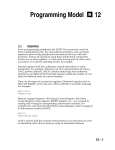
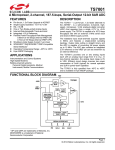
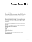
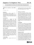
instruction execution has begun. Figure 9.7 shows an example of timing
for the powerdown and restart sequence.
The processor is executing code when the PWD pin is brought low. The
processor vectors to the powerdown interrupt vector and an IDLE
instruction is executed causing the processor to go into powerdown. The
CLKOUT and PWDACK signals are driven high by the processor. At this
point, the input clock pin is ignored. If the processor is put into the
powerdown mode via the powerdown force bit in the powerdown control
register, the result is the same as described above.
The input clock is started and the PWD pin is brought high. After the
necessary start-up cycles the processor brings the PWDACK output low,
begins driving the CLKOUT pin with a clock signal and begins to fetch the
instruction after the IDLE instruction. The processor then resumes normal
operation.
CLKIN
PWD
PWDACK
CLKOUT
RUN
PWRDWN
PENDING
EXECUTE IDLE
POWERED
DOWN
START CLK
RUN
FINISH IDLE
NOP WHILE FETCHING INSTRUCTION FOLLOWING IDLE
Figure 9.7 Powerdown Timing Example
9 – 29
9 System Interface
When powerdown is terminated with the RESET pin or if a start-up delay
is selected, a low level on the PWDACK pin only indicates the start of
oscillations on the CLKOUT pin. It will not necessarily indicate the start of
instruction execution.
The state of PWDACK and also the CLKOUT signal is undefined during
the first 100 cycles of initial reset.
9.7.8
Using Powerdown As A Non-Maskable Interrupt
The powerdown interrupt is never masked. It is possible to use this
interrupt for other purposes if desired. The processor will not go into
powerdown until an IDLE instruction is executed. If an RTI is executed
before the IDLE instruction, then the processor returns from the
powerdown interrupt and the powerdown sequence is aborted.
It is possible to place a series of instructions at the powerdown interrupt
vector location 0x002C. This routine should end with an RTI instruction
and not contain an IDLE instruction if the interrupt is to be used for
purposes other than powerdown.
9 – 30