1
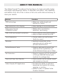
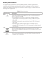
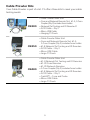
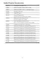
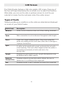
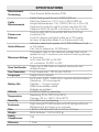
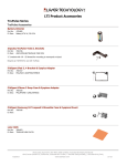
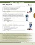
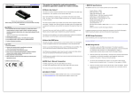
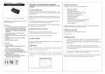
Cable Prowler
TM
Full-Color Cable Testing and Report Management
User Manual
• Displays length measurement for each pair
in feet or meters using TDR technology
• Detects presence of PoE and class of
PoE per IEEE 802.3af/at with load test for
voltage drop
• Detects and reports current link speed and
link capabilities for active Ethernet drops,
up to 1 Gbps
• Link light to identify location on a
hub/switch/router port
• Tests Ethernet cable configuration and
verifies connectivity while conducting tests
for opens, shorts, miswires, split pairs,
and reverses
• Generates selectable tones on selected pins
for use with tone tracers
• Supports up to 8 testing & ID remotes for
network & telephone cables
• Supports up to 20 network & coax ID-only
mapping remotes
• View saved cable tests
• Full color graphical wire-mapping
• Ability to define cable name, save cable
tests, and print all results (cable testing &
network testing)
• Multilingual (English, French, Spanish)
www.t3innovation.com
Cable Prowler
Full-Color Cable Testing and Report Management
User Manual
Table of Contents
About this Manual.......................................................................................3
Safety Information.......................................................................................4
Cable Prowler Kits.......................................................................................5
Cable Prowler Accessories..........................................................................6
Cable Prowler Description...........................................................................7
Remotes...................................................................................................7
LCD Screen..................................................................................................8
Types of Faults.............................................................................................8
Operations.................................................................................................9
On/Off......................................................................................................9
Automatic Power Down............................................................................9
Setup.........................................................................................................10
Changing a Setting....................................................................................11
Cable Testing.............................................................................................12
Cable Testing Guidelines........................................................................12
Safety Notes..........................................................................................12
Length Testing........................................................................................12
Cable Testing with Remotes.................................................................12
How to Perform a Cable Test..................................................................13
Network/Power over Ethernet (PoE) Testing.........................................14
Link Light................................................................................................15
Tone Generator.......................................................................................16
Cable Prowler Application.....................................................................17
Updating Firmware.................................................................................18
Maintenance..................................................................................20
Batteries.........................................................................................20
Cleaning.................................................................................................20
Storage..................................................................................................20
Specifications................................................................................21
Customer Service......................................................................................22
Warranty Information................................................................................23
Product Registration.................................................................................23
Disposal....................................................................................................23
Returns.....................................................................................................23
2
ABOUT THIS MANUAL
The Cable Prowler™ combines the functions of a high-end cable tester
and length-measurement device. It identifies link status, link capability,
and detects PoE. All of this is done in full color with internal memory to
save your results.
Feature
Function
TDR technology
▪▪Measures cable length and
High-resolution color display
▪▪Easy viewing in any environment
Color wire map per
TIA568A/B codes
▪▪Makes data visualization,
detection, and saving
USB, RJ45 and coaxial connectors
▪▪Tests network and coaxial cables
▪▪Easy-to-export results via USB
Tone Generation
▪▪Traces cable runs and locates
faults by sound
Remotes
▪▪Verifies connectivity at the
opposite end of a cable and
provides identification
Active Network Tests
▪▪Detects and reports current link
speed and link capabilities for
active Ethernet drops, up to 1 Gbps
PoE Detection
▪▪Detects presence of PoE and class
of PoE per IEEE 802.3af/at with
load test for voltage drop
Save and View Test Results
▪▪Tests results can be named, saved,
and viewed on the unit
Cable Prowler PC Application
▪▪Provides the ability to upload or
download test results for saving,
viewing, or printing
▪▪Makes it easy to update Cable
Prowler firmware
distance to faults
3
Safety Information
To ensure safe operations of the Cable Prowler, follow instructions
carefully and observe warning and caution messages in this manual.
Failure to observe warnings can result in severe injury or death and can
damage the equipment.
Table 3. Safety Information
Notification
Definition
The Cable Prowler is designed for use on cabling systems
with or without voltage.
▪▪The Voltage! icon turns on when the voltage exceeds
Safety Extra Low Voltage (SELV) rating of 60 Volts peak
AC or DC.
▪▪Internal components are protected up to 400 Volts peak
AC or DC.
▪▪Operating the Cable Prowler when a voltage source
exceeds 60 Volts peak AC or DC may pose a safety hazard
for the user.
Do not place equipment and its accessories in the trash.
Items must be properly disposed of in accordance with local
regulations.
It is not recommended to use the Cable Prowler when the
Voltage! icon is present.
4
Cable Prowler Kits
Your Cable Prowler is part of a kit. T3 offers three kits to meet your cable
testing needs:
CB300
▪▪ Cable Prowler Main Unit
▪▪ Coax and Network Remote Set: #1-5, F-Conn
Coupler (Qty 2) includes foam holder
▪▪ Network/Tel Testing and ID Remote #1
▪▪ RJ12 Cable – Qty 2
▪▪ Micro USB Cable
▪▪ Hanging T3 Pouch
CB350
▪▪Cable Prowler Main Unit
▪▪Coax and Network Remote Set: #1-5,
F-Conn Coupler (Qty 2) includes foam holder
▪▪ #1-8 Network/Tel Testing and ID Remotes
▪▪RJ12 Cable – Qty 2
▪▪Micro USB Cable
▪▪Large T3 Pouch
CB400
▪▪Cable Prowler Main Unit
▪▪#1-8 Network/Tel Testing and ID Remotes
▪▪#1-20 Coax Remotes
▪▪#1-20 Network Remotes
▪▪F-Conn Coupler (Qty 2) includes foam holder
▪▪ #1-8 Network/Tel Testing and ID Remotes
▪▪RJ12 Cable – Qty 2
▪▪TrakAll™ – Tone and Probe
▪▪Micro USB Cable
▪▪Large T3 Pouch
5
Cable Prowler Accessories
AD004
F-Connector Coupler: F81
CA007
Cable Assembly: Micro USB to USB
CA012
Cable Assembly: RJ12, 1-1 pinned, 8 inch
CP100
Hanging T3 Pouch
CP200
Large T3 Pouch
RK120
Coax ID Remote Set:
#1-20 coax ID includes foam holder
RK220
Network ID Only Remote Set:
#1-20 includes foam holder
RK305
Coax and Network Remote Set:
#1-5, F-Conn Coupler includes foam holder
TP200
TrakAll: tone generator and probe
TT001
Network & Telephone Testing/ID Remote #1
TT002
Network & Telephone Testing/ID Remote #2
TT003
Network & Telephone Testing/ID Remote #3
TT004
Network & Telephone Testing/ID Remote #4
TT005
Network & Telephone Testing/ID Remote #5
TT006
Network & Telephone Testing/ID Remote #6
TT007
Network & Telephone Testing/ID Remote #7
TT008
Network & Telephone Testing/ID Remote #8
TT108
Network & Telephone Testing/ID Remotes #1-8
6
Cable Prowler Description
Full-color
LCD display
Soft keys perform the
function on the display
above each button.
Test
Back
Enter
Direction cursors to
move in LCD display
On/Off
RJ45 Jack
USB Port
Coax Connector
Remotes
RK305
Coax Network
Remote Set: #1-5,
F-Conn Coupler
includes foam holder
RK120
Coax Remote Set:
#1-20 coax ID;
includes foam
holder
TT108
Network and
Telephone Testing/ID
Remote Set: #1-8
RK220
Network ID Only
Remote Set: #1-20
includes foam holder
7
LCD Screen
The Cable Prowler features a full-color graphic LCD screen. Press any of
the four soft keys (blue) below the on-screen icon to select that function.
Alternately, you can use the side or up/down arrows to scroll to your
selected on screen function and press enter (the center arrow).
Types of Faults
Several possible error conditions on the cable are detected and displayed
on screen of your Cable Prowler.
Cable Fault
Description
Miswire
Cable’s wire connection does not follow cabling standards.
Open
Wire connection is not continuous throughout cable length.
Short
A pair has a high resistance fault. This occurs when the
wires are making contact with each other due to damage or
improper termination.
Split
A cable can be wired with correct continuity but not with
correct pairing. This most often happens when the cable is
terminated consistently at both ends but in the
wrong order.
Length
Displays the pair lengths found. Length discrepancies may
be determined by these results.
Network
Connectivity
Displays network connectivity which allows the user to
determine if it is different than expected.
PoE
Displays results in red if voltages are lower than expected.
8
OPERATIONS
Follow instructions carefully and pay attention to warning and caution
symbols. Failure to observe warnings can result in severe injury, death,
and damage to the Cable Prowler tester.
On/Off
Turn unit On/Off—press the red button
or turn it off.
Automatic Power Down
to activate the Cable Prowler
The Cable Prowler automatically turns off to conserve battery power if no input
or activity is performed on the device. See “setup” to adjust the length of time
before automatic power down.
9
SETUP
From the main screen, press the blue button on the far right below the
. Use the up and down arrow buttons to scroll
“setup” symbol
through the Setup menu and to select an option.
▪ Use the up and down buttons to navigate through the settings.
▪ Use the right arrow buttons to select setting.
▪ Use the up and down arrow buttons to change the selected setting.
to accept your changes.
▪ Press the enter button
▪ Press the left arrow to unselect a setting.
10
Changing a Setting
▪ RJ45 VoP
: Set the VoP to be used to measure RJ45 cable.
▪ Coaxial VoP
cable.
: Set the VoP to be used to measure coaxial
▪ TIA568A/TIA568B: Set the RJ45 wiring configuration to TIA568A or
TIA568B wiring standard.
▪ Pair/Pin: Set the RJ45 wiremap to measure by pair or pin.
▪ Meters/Feet
Meters or Feet.
: Set the length measurement to be displayed in
▪ Pair/Pin can be changed to test the RJ45 from Wire Order to Pair
Order.
▪ Power Off Timeout
00.5-99.9 minutes.
▪ LCD Dimmer Timeout
00.5-99.9 minutes.
: Set the desired automatic timeout from
: Set the desired automatic timeout from
▪ Language: Set the desired language from English (default) to Spanish
or French.
▪ Tone Generator Timeout: Set the desired automatic timeout 00.5-99.9
minutes.
▪ PoE Test: Turn the PoE test On or Off. Turning the PoE off will allow
the Cable Prowler to detect a network without running a PoE test.
▪ Press the “Calibrate” softkey to calibrate the Cable Prowler. This will
calibrate the Cable Prowler at 0 ft. No cables should be connected to
the Cable Prowler when performing a calibration.
▪ Press the Save soft key to save your options.
Note: If only temporary change is desired, do not press the save
button. If the save button is not pressed, the previous settings
will be restored once the unit is powered off.
▪ To restore factory default values, press the defaults soft key.
▪ To view saved files, press the Files soft key.
11
CABLE TESTING
Cable Testing Guidelines
The Cable Prowler tests coax, network, and phone cables to detect possible
faults, measure cable lengths, show wire pairing and examine a cable’s
physical/electrical properties.
Important Notes:
• RJ jacks for data and phone share internal connections on the
Cable Prowler. Connect just one RJ cable at a time.
• You cannot connect an RJ and coaxial cable at the same time.
• If testing RJ cables, remove any coax cable adapters
Safety Notes
The Cable Prowler is designed for use on cables with voltage below 60V.
Do not plug the device into a source with voltage above 60V. Connecting
the device to live AC power can damage the unit and pose a safety hazard.
Poorly terminated RJ plugs can damage the jacks on the Cable Prowler.
Inspect all RJ plugs before inserting them into the Cable Prowler. Make
sure you insert the plug into the appropriate jack of the remote or device.
Cable contacts should be recessed into the plastic housing of the receiving
jack. Don’t plug a six-position phone plug into an eight-position data jack
on a remote or remote device.
Length Testing
Cable Prowler measures cable length and length to faults using Time
Domain Reflectometry (TDR). Velocity of Propagation (VOP) is the TDR
measurement of the speed of the reflected waveforms compared to the speed
of light. VOP values can vary among cable types, lots, and manufacturers. In
most cases, these differences are minor and may be disregarded.
Cable Testing with Remotes
#1-8 Network/Tel Cable Prowler remotes (P/N TT108) are used to verify
connectivity at the opposite end of a cable and provide an ID. To connect
to a telephone cable, use the included RJ12 no fault telephone patch
cables to connect to a RJ11 wall plate. The 1-20 Coax (P/N RK120) and
1-20 Network (P/N RK220) remotes are used to provide an ID.
12
How to Perform a Cable Test
▪ Power on the Cable Prowler.
▪ Connect a network, coax, or telephone cable to the appropriate connector on the top of the Cable Prowler.
(Warning! Do not plug an RJ11 cable directly into the Cable Prowler.
A standard RJ11 cable will damage the Cable Prowler’s RJ45 jack.
Use the RJ adapter patch cable (CA012) that is included with the
Cable Prowler.)
▪ Press the enter button to display the cable test menu. The Cable
Prowler will automatically perform a test upon entering the cable test
menu.
▪ To test coax or telephone cable, press the coax or telephone soft key.
▪ If a remote is NOT being used (one ended test), the Cable Prowler will
test the length of each pair, opens, shorts, or split pairs. Performing
a one ended test will not verify connectivity on the opposite end of
the cable.
▪ If a remote is being used, connect the remote to the opposite end of
the cable.
▪ To calibrate the VOP, connect a known length of cable to the Cable
Prowler and press the up/down/left/right buttons to increase or decrease the VOP. Press the left and right buttons to select and change
the VOP one digit at a time.
▪ While adjusting the VOP, press the test button until the desired
length of the cable is displayed.
▪ To save the calibrated VOP, enter the settings menu and press the
Save soft key (note: your adjusted VoP will be displayed next to the
RJ45 or Coax icon.
or the loop mode soft key
▪ Press the green test button
to perform additional tests.
▪ To save a cable test, press the save icon.
▪ Use the arrow buttons and the enter button to name the cable test file.
▪ Press the Save icon to save the cable test file.
13
Network / Power over Ethernet (PoE) Testing
The Cable Prowler PoE test identifies the link capability of a network drop
and the connection status. Cable Prowler detects the presence of PoE, PoE
class per IEEE 802.3 af/at, and also measures PoE voltages under load.
The Network/PoE tests can be saved for record keeping and printing.
▪ Power on the Cable Prowler.
▪ Connect the Cable Prowler to a switch or active network jack.
▪ Use the left or right arrow buttons to select the Network/PoE icon
and press the enter button or press the Network/POE soft key.
▪ The Cable Prowler will automatically detect and display link capability, connection speed, PoE class, and PoE Min/Max voltages.
▪ To perform a Network Test only, press the PoE soft key.
▪ To save the PoE data, press the Save soft key.
▪ Use the arrow buttons and the enter button to name the PoE file.
▪ Press the Save soft key to save the PoE file.
14
Link Light
The Link Light test is used to help identify a hub or switch port.
▪ Power on the Cable Prowler.
▪ Connect the Cable Prowler to an active Network cable or port.
▪ Press the Network/PoE soft key
then press the Link Light
soft key.
▪ The Link Light will automatically begin upon entering the Link Blink
menu.
▪ The Link LED above the LCD screen will flash at the same cadence as
the port light.
▪ Use the up and down arrows to adjust the transmit frequency to suit
the switch characteristics.
15
Tone Generator
Tone generation is used to trace cable runs and locate faults by sound.
Selection of this mode emits a cadence from the Cable Prowler through
the connected cable. The tone is detected by a tone tracer probe, sold
separately. Refer to the Accessories section.
▪ Power on the Cable Prowler.
▪ Use the left or right arrow buttons to select the tone generator
icon and press the enter button.
▪ The Cable P rowler will automatically activate the tone generator
upon entering the tone generator menu.
▪ Connect your cable to either the RJ45 jack or coax connector located
on the top of the Cable Prowler.
▪ To switch between network and coax cables, press the coax cable/
RJ45 soft key
/
.
▪ Press the up or down arrow buttons to select tone cadences 1 thru 4.
▪ Press the left or right arrow buttons to select which pin or pair to
place the tone.
▪ Use a tone probe (P/N TP200 TrakAll) alongside the cable or at the
end of the cable to hear an audible tone.
16
Cable Prowler Application
The Cable Prowler Application gives you the ability to view, save and print
cable and network test results on your computer. This application can also
update your Cable Prowler’s firmware.
To install the Cable Prowler application
▪ Go to www.t3innovation.com/downloads to download the Cable
Prowler software application.
▪ Save the Cable-Prowler-Application.zip file to your computer’s
desktop. Double click on the zip file to open it.
▪ Double-click on “setup.exe” to begin the installation.
To view test results on your computer
▪ Open the Cable Prowler application .
▪ Connect the Cable Prowler to your computer with the included USB
cable.
▪ Power on the Cable Prowler
. The software will display “Cable
Prowler connected” at the bottom left of the screen.
▪ Click the “Read Cable Prowler” icon to read the test results. The cable
names will be displayed on the top left of the screen. The first cable
name will automatically be selected and displayed at the top right.
▪ Click on the cable IDs on the left of the screen to view test results for
that ID.
▪ You may delete a single test by selecting it and “Delete”, or to delete
the entire test list click on “Delete All Tests.”
To save the cable results to your computer
▪ Click on “File” on the tool bar at the top left.
▪ Click on “Save File.” A “Save As” dialogue will appear; navigate to
where you want to save the test results and click “Save.” You can
also rename the file in the “Save As” dialog window. The computer
software application will remember the last place you saved a file.
To read previously saved cable tests
▪ Click on “File,” “Open,” and select the desired test result file.
▪ After tests have been saved, they will automatically be reloaded the
next time the Application is opened.
17
To write cable tests to the Cable Prowler
▪▪Connect the Cable Prowler to your computer using the included USB
cable.
▪▪Open the Cable Prowler software application. Click on “File”, “Open”,
and select the desired cable tests.
▪▪Click on “Write Prowler” and the contents of the currently displayed
tests will be written to the Cable Prowler.
To print a test
▪▪Select the desired test.
▪▪Click on “File,” “Print”
To create and print test results report
▪▪First select the tests to be included in the report in the Test Results
list box. To select multiple tests do one or more of the following.
▪▪Click on a test and drag to the end of a range of tests.
▪▪Click on the first desired test, then Shift click on the last desired
test
▪▪Press the Control Key and click on a test to add or delete it from
the selected tests.
▪▪Select Create Report Pdf under the File menu.
▪▪When a Dialog box comes up, select the file name and location for
the Pdf file to be saved.
18
Updating Firmware
To Download the New Cable Prowler Firmware
▪ Go to www.t3innovation.com/downloads.
▪ Click on the Cable Prowler Firmware update link to download the
new firmware.
▪ Save the Cable Prowler.cyacd file to your computer.
Updating the Cable Prowler
▪ Connect the Cable Prowler to your computer using the included USB cable.
▪ Power on the Cable Prowler
. The software will display “Cable
Prowler Connected” at the bottom left of the screen.
▪ Click the “Load File” icon and select the desired Cable Prowler.cyacd
firmware file. Click the “Begin Download” icon.
▪ The Cable Prowler screen will go dark and it will begin the firmware
installation (the screen will remain dark during the installation).
▪ The Cable Prowler Application will display a progress bar to indicate
the download progress.
▪ Once complete, the Cable Prowler application will display “success”
along with the installation date and time in the Status Log window.
The Cable Prowler will power itself back on after the firmware
installation.
▪ If the Cable Prowler is interrupted or an error occurs during
installation the Cable Prowler screen will remain dark. To recover
the Cable Prowler firmware, close the Cable Prowler application,
disconnect the Cable Prowler from the USB cable, then remove the
batteries. Reinsert the batteries and follow the update instructions.
Important Notes: The Cable Prowler screen will remain dark
until it has been reprogrammed.
19
MAINTENANCE
Batteries
▪▪The Cable Prowler is powered by six AA alkaline batteries.
▪▪To replace batteries, open the back cover by unscrewing the single
screw with a philips head screwdriver.
▪▪Take out the old batteries and replace. Slide the new batteries in by
following the directional guidelines in the battery chamber.
▪▪Screw the back cover back on to the Cable Prowler. Do not over
tighten the battery back cover.
Warning: Do not use carbon batteries. Do not mix new batteries with
old batteries, due to the risk of battery leakage.
Cleaning
▪▪Use a clean, damp cloth to clean the Cable Prowler.
▪▪Before cleaning, disconnect all cables from the Cable Prowler. Failing to
disconnect cables can damage the device and cause personal injury.
▪▪Do not use harsh cleaners, abrasives, or solvents.
Storage
▪▪When not in use, store the Cable Prowler in a dry, protective case.
▪▪Batteries should be removed if the device is stored for a long time.
▪▪Do not expose the Cable Prowler to high temperatures or humidity.
See the specifications section for temperature limits.
20
SPECIFICATIONS
Measurement
Technology
Time Domain Reflectometry (TDR)
Cable Testing and ID: up to 1000 ft (305 m)
Split Pair Detection: 3 ft (1 m) to 1,000 ft (305 m)
Cable
Length Measurement: 0 to 1,500 ft (457 m), ± (5%+1ft)
Measurements
Supports 8 continuity and ID number remotes (RJ-45)
Supports 20 RJ-45 and 20 F-Connector ID only remotes
Tests for IEEE 802.3af and IEEE 802.3at (PoE Plus)
Power over
compliant PoE
Ethernet
Tests for classes and loads cable up to 25.5 watts
(at class 4) Identifies Mode A or B (pairs with PoE)
Indicates advertised speeds of 10/100/1000base-t half
Active Ethernet
or full duplex
Can Link to network at 10/100base-t
Parameters refer to the maximum voltage that can be
applied to any 2 connector pins without causing damage
Maximum Voltage to the tester.
• RJ Jack: 66 VDC or 55 VAC
• F-connector: 50 VDC or VAC
Stores up to 256 Cable or network tests with user
Save Test Results
defined names
Tone Generation
Tone Frequencies: 730 Hz and 1440 Hz
Languages
English, French, Spanish
For 6 x AA, 9 VDC, 2,200 mA-hr (typical) alkaline battery:
Operating – 20 hours typical
Battery Life
Standby – 1.5 years typical
(200uA max standby current)
Batteries are included
Altitude
10,000 ft (3048 m) operating
Operating: 32 to 122°F (0 to 50°C)
Temperature
Storage: -22 to +140°F (-30 to 60°C)
Humidity
10 to 90% non-condensing
High-strength PC/ABS plastic with V0 rating with boot
Enclosure
Withstands 4 foot drop on to concrete
Size
1.85”H x 3.6”W x 6.8”L (4.7 x 9.15 x 17.3 cm)
Weight
With batteries: 1 lb 2 oz (510 g)
Safety
CW
Compliances
Warranty
1 Year
21
CUSTOMER SERVICE
Contacting T3 Innovation
For technical information and customer support, please visit
www.t3innovation.com or send an email to [email protected].
Contact Numbers: Phone: 805-233-3390
Fax: 805-383-4507
Address: 808 Calle Plano
Camarillo, CA 93012
USA
22
Warranty Information
T3 Innovation guarantees that its products will be free of all defects in
material and workmanship. This warranty extends for a period of 12
months for the T3 Innovation test equipment from the date of manufacture
or proof-of-purchase.
All products deemed defective under this warranty will be repaired or
replaced at T3 Innovation’s discretion. No further warranties either
implied or expressed will apply, nor will responsibility for operation of this
device be assumed by T3 Innovation.
Product Registration
Registration of your purchased equipment and accessories allows you to
access support information and receive notifications of product updates.
To register products, please visit the T3 Innovation website at
www.t3innovation.com/warranty.
Disposal
WEEE Compliant: Prior to disposal of this product, please
contact T3 Innovation for proper disposal options.
Returns
Prior to returning any product to T3 Innovation, you must first request a
Return Merchandise Authorization Number by contacting the Customer
Service Department at 805-233-3390.
Note: Shipments will not be accepted without this number, which
must be clearly marked on the shipping label.
1. Prior to packing, include a copy of the sales receipt if available.
Otherwise the date of manufacturer will be used to calculate
warranty date.
2. Provide a description of the operational problem with the product(s)
being returned.
3. Include a contact name, phone number, and e-mail address.
4. Pack items securely to prevent damage during shipping.
5. Ship prepaid to:
T3 Innovation
808 Calle Plano
Camarillo, CA 93012
USA
23
Cable Prowler
TM
Full-Color Cable Testing and Report Management
User Manual
For technical information and customer support,
please visit www.t3innovation.com or send an
email to [email protected].
Contact Numbers: Phone: 805-233-3390
Fax: 805-383-4507
Address: 808 Calle Plano
Camarillo, CA 93012
USA
www.t3innovation.com