1
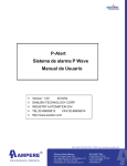
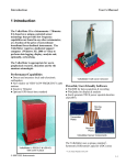
Palert P Wave Alarm System User Manual Version: 1.00 2010/04 SANLIEN TECHNOLOGY CORP. INDUSTRY AUTOMATION DIV. TEL:02-86659813 FAX:02-86659814 http://www.sanlien.com 1 / 40 Palert V1.00 1. Features................................................................................................................................. 6 2. Application Topology .............................................................................................................. 7 3. Hardware information ............................................................................................................ 8 3.1. Wiring .......................................................................................................................... 8 3.2. Information for LED Display ........................................................................................ 8 3.3. Digital Inputs Configurations ....................................................................................... 9 ◎ Reset to Factory Setting ........................................................................................ 9 ◎ Display IP Information.......................................................................................... 10 ◎ Display The Last Earthquake Information ........................................................... 10 3.4. RTD (Real Time Data stream) Output Control .......................................................... 10 3.5. Parameters for Autoexec.bat......................................................................................11 3.6. DOs Wiring and Characteristics .................................................................................11 3.7. DIs Wiring ...................................................................................................................11 3.8. Installation ................................................................................................................. 12 4. Parameters Setup................................................................................................................ 13 4.1. Parameters List ......................................................................................................... 13 4.2. Parameters Description............................................................................................. 17 ◎Address 100, NTP Synchronal and Server Connected Flag................................. 17 ◎Address 101, Real-Time a Axis Acceleration ........................................................ 17 ◎Address 102, Real-Time b Axis Acceleration ........................................................ 17 ◎Address 103, Real-Time c Axis Acceleration......................................................... 17 ◎Address 104, Real-Time Vector Acceleration........................................................ 18 ◎Address 105, a Axis Offset .................................................................................... 18 ◎Address 106, b Axis Offset .................................................................................... 18 ◎Address 107, c Axis Offset .................................................................................... 18 ◎Address 108, Maximum Vector in Earthquake ...................................................... 18 ◎Address 109, Real-Time Earthquake Intensity...................................................... 18 ◎Address 110, Maximum Intensity in Earthquake ................................................... 19 ◎Address 111, Earthquake Indicator........................................................................ 19 ◎Address 112, LTA Ready Indicator ........................................................................ 19 ◎Address 113, Setup Parameters............................................................................ 19 ◎Address 114, Time Zone........................................................................................ 20 ◎Address 115, STA Duration ................................................................................... 20 ◎Address 116, LTA Duration .................................................................................... 20 ◎Address 117, STA/LTA Trigger Threshold.............................................................. 20 ◎Address 118, Operation Mode............................................................................... 20 ◎Address 119, DI/Os Status .................................................................................... 21 2 / 40 Palert V1.00 ◎Address 120, Earthquake Event Sustained Duration ............................................ 22 ◎Address 121, PGA Watch Threshold..................................................................... 22 ◎Address 122, Numbers Of Records For Offset Calculation .................................. 22 ◎Address 123 and 124, DOs Activated Setting ....................................................... 22 ◎Address 125, PGV within 1 Second ...................................................................... 23 ◎Address 126, PGD within 1 Second ...................................................................... 23 ◎Address 127, Information for Last Earthquake...................................................... 23 ◎Address 128, Real-Time STA/LTA ......................................................................... 23 ◎Address 129, Maximum a Axis Acceleration in Earthquake .................................. 23 ◎Address 130, Maximum b Axis Acceleration in Earthquake .................................. 23 ◎Address 131, Maximum c Axis Acceleration in Earthquake .................................. 24 ◎Address 132, Maximum a Axis Acceleration of Vector in Earthquake................... 24 ◎Address 133, Maximum b Axis Acceleration of Vector in Earthquake................... 24 ◎Address 134, Maximum c Axis Acceleration of Vector in Earthquake................... 24 ◎Address 135, PGA Trigger Axis ............................................................................. 24 ◎Address 136, Real-time a AXIS Velocity ............................................................... 24 ◎Address 137, Real-time a Axis Pd......................................................................... 24 ◎Address 138, Real-time a Axisτc ........................................................................... 24 ◎Address 139, Pd Trigger Status............................................................................. 24 ◎Address 140, PGA Within 10 Seconds.................................................................. 25 ◎Address 141, Earthquake Time – Year.................................................................. 25 ◎Address 142, Earthquake Time – Month ............................................................... 25 ◎Address 143, Earthquake Time – Day................................................................... 25 ◎Address 144, Earthquake Time – Hour ................................................................. 25 ◎Address 145, Earthquake Time – Minute .............................................................. 25 ◎Address 146, Earthquake Time – Second............................................................. 25 ◎Address 147, System Time – Year ........................................................................ 25 ◎Address 148, System Time – Month ..................................................................... 25 ◎Address 149, System Time – Day ......................................................................... 25 ◎Address 150, System Time – Hour........................................................................ 25 ◎Address 151, System Time – Minute..................................................................... 26 ◎Address 152, System Time – Second ................................................................... 26 ◎Address 153, Set System Time – Year.................................................................. 26 ◎Address 154, Set System Time – Month ............................................................... 26 ◎Address 155, Set System Time – Day................................................................... 26 ◎Address 156, Set System Time – Hour ................................................................. 26 ◎Address 157, Set System Time – Minute .............................................................. 26 ◎Address 158, Set System Time – Second............................................................. 27 3 / 40 Palert V1.00 ◎Address 159, Real-time a Axis Displacement ....................................................... 27 ◎Address 160, a Axis Displacement Warning Threshold ........................................ 27 ◎Address 161, PGA Warning Threshold.................................................................. 27 ◎Address 162, Pd Warning Threshold..................................................................... 27 ◎Address 163, Trigger Mode and Low Pass Filter Select ....................................... 27 ◎Address 164, Pd Watch Threshold........................................................................ 28 ◎Address 165, Calibration Factor for a Axis at 0 g .................................................. 28 ◎Address 166, Calibration Factor for b Axis at 0 g .................................................. 28 ◎Address 167, Calibration Factor for c Axis at 0 g .................................................. 28 ◎Address 168, Calibration Factor for a Axis at 1 g .................................................. 29 ◎Address 169, Calibration Factor for b Axis at 1g ................................................... 29 ◎Address 170, Calibration Factor for c Axis at 1 g .................................................. 29 ◎Address 171~174, NTP Server IP ......................................................................... 30 ◎Address 175, Weekday ......................................................................................... 30 ◎Address 176~177, TCP Server 0 IP ...................................................................... 30 ◎Address 178~179, TCP Server 1 IP ...................................................................... 30 ◎Address 180~191, Palert Network Address Setting .............................................. 31 ◎Address 192, Available Connections for Host ....................................................... 31 ◎Address 193, Streaming Output Control................................................................ 32 ◎Address 194, Palert Modbus RTU Address setting ............................................... 34 ◎Address 195, Watch and Warning Period ............................................................. 34 ◎Address 196, Maximum Acceleration within 1 Second ......................................... 34 ◎Address 197, a Axis Displacement Watch Threshold ........................................... 34 ◎Address 198, Earthquake Pre-Warning Register .................................................. 34 ◎Address 199, Palert Firmware Number ................................................................. 35 ◎Address 200, Palert Serial Number....................................................................... 35 4.3. Modbus Related Information for Palert ..................................................................... 35 4.4. Palert Operation Time Sequence .............................................................................. 36 4.4.1. Power ON Time Sequence ............................................................................. 36 4.4.2. Parameter Setting Time Sequence ................................................................. 36 4.4.3. Initialization Time Sequence ........................................................................... 37 4.4.4. STA/LTA Trigger Time Sequence .................................................................... 37 4.4.5. Displacement, Pd, and PGA Trigger Time Sequence ..................................... 38 Table 1. Earthquake Intensity Table, Central Weather Bureau, Taiwan. ................................. 39 Appendix 1. EEW Paper by Professor Yih-Min Wu., National Taiwan University.................... 40 4 / 40 Palert V1.00 Revisions Date Description Author 20100418 The first edition 1.00 Ching 20100429 Some phrases correction Ching 20100622 1. Streaming packet size is increased from 1100 to 1200 Ching bytes. 2. Add DI/O status and EEW register in streaming packet. 3. Modify description for DI/O wiring. 4. Add quit program and FTP update description for address 113. 5. Add Pa, Pv and Pd in streaming packet. 6. Add streaming packet type 300, 1191 and 1192. 7. FTP server IP setting 5 / 40 Palert V1.00 1. Features Palert, an advanced technology earthquake P wave alarm embedded Pd technology which is developed by Prof. Yih-Min Wu, National Taiwan University. Design to reduce earthquake damage that an alarm can be issued within 3 seconds after P wave is detected if following shock wave is destructive. Offer four kinds of trigger algorithms Pd, PGA, Displacement and STA/LTA for detect earthquake. The Pd algorithm is developed by Prof. Yih-Min Wu. Please refer to related documents have been published. PGA stands for Peak Ground Acceleration. Palert offers 10 Hz and 20 Hz low pass filter which is selected by user to filter out high frequency components in signal generated by non-earthquake vibration. Component “a” is especially equips with realtime displacement calculation which is able to deploy displacement trigger algorithm in “a” axis. The conventional STA/LTA trigger algorithm is also available on Palert. Intensity standards both for CWB (Central Weather Bureau, Taiwan) and China (GB/T-17742-2008) are available. Other useful earthquake information is stored and ready for retrieved in Palert. These include trigger time, maximum intensity, maximum acceleration for each component and maximum acceleration in vector. The powerful networking capability features streaming real-time data to hosts; automatically connect to up to 2 servers, NTP (Network Time Protocol) time calibration. With these networking functions Palert is a wonderful front end device for EEW (Earthquake Early Warning) system. With PC utility it is possible to record earthquake data for research purpose and have voice warning if needed. Two outputs and supports industrial Modbus TCP/RTU communication standard which make Palert an ideal product for earthquake safety control in numerous applications. 6 / 40 Palert V1.00 2. Application Topology NTP Server SCADA or PC Modbus TCP TCP / IP Relays HMI Palert 緊急關機 RS-232 Standard Configuration SCADA or PC Modbus RTU HMI Only one Modbus RTU host can be connected 7 / 40 Palert V1.00 3. Hardware information 3.1. Wiring Pin Definition Description GND Power Ground Vs+ Power 10~30VDC 300mA D2- COM2, Modbus RTU (RS-485 D-) D2+ COM2, Modbus RTU (RS-485 D+) INIT* For Service only. Please do not connect. TXD1 COM1 TX RXD1 COM1 RX RTS1 COM1 RTS CTS1 COM1 CTS E1 DO PWR DO0 Modbus TCP (10 / 100M Ethernet Port) DC5V Output Relay Output 0 (Photo MOS Relay, Form A) Normal Open , 0.6A/60VDC DO1 Relay Output 1 (Photo MOS Relay, Form A) Normal Open , 0.6A/60VDC DO COM GND Common for Relay Output 0 and 1. 0V DI0 Digital Input 0 (LED display will show IP when grounding) DI1 Digital Input 1(LED display will show last event information when grounding) DI2 Digital Input 2 (RTD Output Mode) DI3 Digital Input 3 (Reserved) 3.2. Information for LED Display Normal Status Display will illustrate three kinds of information periodically which are “YYYY.MM.DD WWW”, “hh.mm” and “.ss.”. It will blink if NTP synchronal function is enabled and Palert is unable to synchronize with NTP server. YYYY : Year MM : Month DD : Day WWW : Weekday hh : Hour 8 / 40 Palert V1.00 mm : Minute ss : Second Earthquake Detected Display will illustrate three kinds of information periodically which are maximum intensity, maximum acceleration and what kinds of earthquake trigger algorithms are set. If Palert is configured as CWB intensity based mode then the information is “IIIII”, “VVVV.V” and “P.d.A.t.”. I : Maximum Intensity VVVV.V : Maximum Acceleration in Gal Unit P. : Pd Event Triggered d. : Displacement Event Triggered A. : PGA Event Triggered t. : STA/LTA Event Triggered If Palert is configured as GB/T 17742-2008 intensity based mode then the information is “I”, “VV.VVV” and “P.d.A.t.”. I : Maximum Intensity VV.VVV : Maximum Horizontal Acceleration in m/sec^2 Unit P. : Pd Event Triggered d. : Displacement Event Triggered A. : PGA Event Triggered t. : STA/LTA Event Triggered Earthquake Pre-warning Information Sent by Server When Palert is deployed as an EEW (Earthquake Early Warning) system front end device, it is possible sending EEW information to Palert in order to have earthquake pre-warning time for people. The information is “II.-99”. II : Expected Intensity -99 : Expected Earthquake Shockwave Arrival Time in Seconds. Attention! This function is only available when Palert is connected to seismologic server which has advanced seismology program. Please consult your local distributor if you have EEW application requirement. User must be noticed to follow the individual countries earthquake dispatch regulations or laws. 3.3. Digital Inputs Configurations ◎ Reset to Factory Setting Palert will restore all parameters to factory default setting if all four DIs are grounding. 9 / 40 Palert V1.00 ◎ Display IP Information When DI0 is grounding Palert will display IP information as “XXX.XXX.XXX.XXX” format. ◎ Display The Last Earthquake Information Palert will display the last earthquake information when DI1 is grounding. The display format is described as below. CWB Intensity Based Mode: “YYYY.MM.DD hh.mm.ss I.I.I.I.I VVVV.V” YYYY : Year MM : Month DD : Day hh : Hour mm : Minute ss : Second I : Maximum Intensity V : Maximum Acceleration in Gal Unit. GB/T 17742-2008 Based Mode: “YYYY.MM.DD hh.mm.ss II VV.VVV” YYYY : Year MM : Month DD : Day hh : Hour mm : Minute ss : Second II : Maximum Intensity V : Maximum Horizontal Acceleration in m/sec^2 Unit. 3.4. RTD (Real Time Data stream) Output Control When DI2 is grounding Palert will enable RTD output function. The data format is described as below. Byte 1 Byte 2 Byte 3 Byte 4 Byte 5 Byte 6 Byte 7 Byte 8 0x0d a High a Low b High b Low c High c Low 0x0a The data output serial port is determined by “autoexec.bat” file in Palert. The communication protocol is “9600, n, 8, 1”. Please refer to next section for more information about “autoexec.bat”. User must be noticed that all DOs will be controlled by RTD serial port and the data are raw without filtered. The DOs control commands are described as below. DO0 ON OFF #ON0#\r #OFF0#\r 10 / 40 Palert V1.00 DO1 #ON1#\r #OFF1#\r \r stands for 0x0d 3.5. Parameters for Autoexec.bat There are two parameters for “autoexec.bat” file for Palert as below. Example: runexe 2 N Parameter 1: Modbus RTU Port Possible options are 1 or 2. RTD output function will be enabled when DI2 is grounding. The RTD serial port is automatically switched to the other port. For this example, Modbus RTU port is 2 and RTD port is 1. Parameter 2: DHCP Client Enable The possible options are “Y” and “N”. Attention! All these two parameters should be maintained by professional with precise setting. Otherwise, it will cause Palert malfunction. 3.6. DOs Wiring and Characteristics DO is acted just like a switch but with contact capacity as 60V 0.6A. Please refer to wiring diagram as below. 3.7. DIs Wiring Please refer to DI wiring diagram as below. 11 / 40 Palert V1.00 3.8. Installation Due to the earthquake trigger algorithm Palert adapted that a axis should be installed as vertical component. It is recommended to have anti-impact transparent housing covered to avoid artificial impact. A backup battery is also good configuration to prevent power failure. 12 / 40 Palert V1.00 4. Parameters Setup The parameters of Palert have been setup optimally. However, due to different installation location and background noise, some adjustments for parameters are necessary. Each function of Palert parameters are described as below. Please notes that below address are zero based. 4.1. Parameters List Palert Modbus Address Mapping Table (400XXX) Address R/W Label Description NTP Server Synchronal and Servers Connected 100 R connection_flag 101 R a_axis Real-Time a Axis Acceleration 102 R b_axis Real-Time b Axis Acceleration 103 R c_axis Real-Time c Axis Acceleration 104 R vector Real-Time Vector Acceleration 105 R a_offset a Axis Offset 106 R b_offset b Axis Offset 107 R c_offset c Axis Offset 108 R vector_gal_max Maximum Vector in Earthquake (Unit : gal) 109 R intensity_now Real-Time Intensity 110 R intensity_max Maximum Intensity in Earthquake 111 R event Earthquake Indicator 112 R lta_flag LTA Ready Indicator Flag Setup Option 113 W data_changed (1 as Update, 2 as Write to EEPROM, 4 as Write IP Address Setting to EEPROM, 8 as Update System Time) 114 RW time_diff GMT Time Zone (Taipei is 8) 115 RW sta_time STA Duration (Unit : 100 ms) 116 RW lta_time LTA Duration (Unit : 100 ms) 117 RW sta_lta_th STA/LTA Trigger Threshold GB/T 17742-2008 Mode, DO Control Mode, 118 RW op_mode Intensity Calculated Standard, Servers Connection and NTP Enable, Streaming Enable 119 R DIO_status DI and DO status 120 RW event_time Earthquake Event Sustained Duration (Unit : 13 / 40 Palert V1.00 Palert Modbus Address Mapping Table (400XXX) second) 121 RW pga_watch_threshold PGA Watch Threshold (Unit: count) 122 RW offset_records Numbers of Records for Offset Calculation 123 RW DO0_gal DO0 Activated Setting (Unit : gal) 124 RW DO1_gal DO1 Activated Setting (Unit : gal) 125 R PGV_1S Peak Ground Velocity (Unit: 0.001 cm/sec) 126 R PGD_1S Peak Ground Displacement (Unit: 0.001 cm) 127 R last_event Information for Last Earthquake 128 R sta_lta Real-Time STA/LTA 129 R a_maximum Maximum a Axis Acceleration in Earthquake 130 R b_maximum Maximum b Axis Acceleration in Earthquake 131 R c_maximum Maximum c Axis Acceleration in Earthquake 132 R vector_max_a 133 R vector_max_b 134 R vector_max_c 135 RW pga_trig_axis PGA Trigger Axis 136 R pv_int Real-Time a Axis Velocity (Unit: 0.001 cm/sec) 137 R pd_int Real-Time a Axis Pd (Unit: 0.001 cm) 138 R tc_int Real-Time a Axis 139 R pd_flag Pd Trigger Status 140 R pga_10s PGA Within 10 Seconds (Unit: count) 141 R e_year Earthquake Time – Year 142 R e_month Earthquake Time – Month 143 R e_day Earthquake Time – Day 144 R e_hour Earthquake Time – Hour 145 R e_minute Earthquake Time – Minute 146 R e_second Earthquake Time – Second 147 R sys_year System Time – Year 148 R sys_month System Time – Month 149 R sys_day System Time – Day 150 R sys_hour System Time – Hour Maximum a Axis Acceleration of Vector in Earthquake Maximum b Axis Acceleration of Vector in Earthquake Maximum c Axis Acceleration of Vector in Earthquake 14 / 40 τc (Unit: 0.001) Palert V1.00 Palert Modbus Address Mapping Table (400XXX) 151 R sys_minute System Time – Minute 152 R sys_second System Time – Second 153 RW set_year Set System Time – Year 154 RW set_month Set System Time – Month 155 RW set_day Set System Time – Day 156 RW set_hour Set System Time – Hour 157 RW set_minute Set System Time – Minute 158 RW set_second Set System Time – Second 159 R displacement Real-Time a Axis Displacement (Unit: 0.001 cm) 160 RW disp_warning_threshold 161 RW pga_warning_threshold PGA Warning Threshold (Unit: count) 162 RW pd_warning_threshold Pd Warning Threshold (Unit: 0.001 cm) 163 RW trig_mode Trigger Mode and Low Pass Filter Select 164 RW pd_watch_threshold Pd Watch Threshold (Unit: 0.001 cm) 165 RW a_0g Calibration Factor for a Axis at 0 g (Unit: 0.1 mg) 166 RW b_0g Calibration Factor for b Axis at 0 g (Unit: 0.1 mg) 167 RW c_0g Calibration Factor for c Axis at 0 g (Unit: 0.1 mg) 168 RW a_1g Calibration Factor for a Axis at 1 g (Unit: 0.1 mg) 169 RW b_1g Calibration Factor for b Axis at 1 g (Unit: 0.1 mg) 170 RW c_1g Calibration Factor for c Axis at 1 g (Unit: 0.1 mg) 171 RW ntp_svr_ip1 NTP Server IP Address 1 172 RW ntp_svr_ip2 NTP Server IP Address 2 173 RW ntp_svr_ip3 NTP Server IP Address 3 174 RW ntp_svr_ip4 NTP Server IP Address 4 175 R week_day System Time – Weekday 176 RW server0_ip12 Server0 IP Address 1, 2 177 RW server0_ip34 Server0 IP Address 3, 4 178 RW server1_ip12 Server1 IP Address 1, 2 179 RW server1_ip34 Server1 IP Address 3, 4 180 RW IP1 Palert IP address 181 RW IP2 Palert IP address 182 RW IP3 Palert IP address 183 RW IP4 Palert IP address A Axis Displacement Warning Threshold (Unit: 0.001 cm) 15 / 40 Palert V1.00 Palert Modbus Address Mapping Table (400XXX) 184 RW Subnet mask 1 Palert IP subnet mask 185 RW Subnet mask 2 Palert IP subnet mask 186 RW Subnet mask 3 Palert IP subnet mask 187 RW Subnet mask 4 Palert IP subnet mask 188 RW Gateway 1 Palert IP gateway 189 RW Gateway 2 Palert IP gateway 190 RW Gateway 3 Palert IP gateway 191 RW Gateway 4 Palert IP gateway 192 R sck_remain Available Connections for TCP Host 193 RW stream_output Streaming Output Control 194 RW rtu_address Palert Modbus RTU Address 195 RW light_sound_duration Watch and Warning Period 196 R vector_gal_now Maximum Acceleration Within 1 Second (Unit: gal) 197 RW disp_watch_threshold a Axis Displacement Watch Threshold 198 RW pre-alarm Earthquake Pre-Warning Register 199 R version Firmware Number 200 R serial_no Palert Serial Number 16 / 40 Palert V1.00 4.2. Parameters Description ◎Address 100, NTP Synchronal and Server Connected Flag bit 0 0: Palert not synchronize with NTP server. 1: Palert has synchronized with NTP server. The synchronal interval is 10 minutes and Palert will try to synchronize with NTP server every 10 seconds if last synchronization failed. The new connection will be established if there is no synchronization within 700 seconds. Regarding the IP address setting for NTP server please refer to addresses 171 to 174. bit 1 0: Indicate that there is no connection with server 0. 1: Indicate that connection between server 0 and Palert has established. Regarding the IP address setting for server 0 please refer to addresses 176 and 177. bit 2: 0: Indicate that there is no connection with server 1. 1: Indicate that connection between server 1 and Palert has established. Regarding the IP address setting for server 1 please refer to addresses 178 and 179. All functions mentioned above will only available when NTP or servers connection is enabled. Please refer to address 118 for related setting. ◎Address 101, Real-Time a Axis Acceleration This address stores real-time a axis acceleration, unit in count. One gal is equal to 16.7184 counts. The throughput is 100 samples / second when connected up to 3 hosts in Ethernet environment. ◎Address 102, Real-Time b Axis Acceleration This address stores real-time b axis acceleration, unit in count. One gal is equal to 16.7184 counts. The throughput is 100 samples / second when connected up to 3 hosts in Ethernet environment. ◎Address 103, Real-Time c Axis Acceleration This address stores real-time c axis acceleration, unit in count. One gal is equal to 16.7184 counts. The throughput is 100 samples / second when connected up to 3 hosts in Ethernet environment. 17 / 40 Palert V1.00 ◎Address 104, Real-Time Vector Acceleration This address stores real-time vector acceleration, unit in count. One gal is equal to 16.7184 counts. The throughput is 100 samples / second when connected up to 3 hosts in Ethernet environment. The equation of vector is described as below. Vector = a 2 + b 2 + c 2 ◎Address 105, a Axis Offset This address stores a axis offset compensation value, unit in count, One gal is equal to 16.7184 counts. The zero point output of accelerometer will be affected by installation or some other issues. This value will only calculate at initialization. Palert equips automatic zero algorithm so it is no need to calculate offset after initialization. Due to installation that a axis will face gravity so there is around -980 gal offset in this axis. ◎Address 106, b Axis Offset This address stores b axis offset compensation value, unit in count, One gal is equal to 16.7184 counts. The zero point output of accelerometer will be affected by installation or some other issues. This value will only calculate at initialization. Palert equips automatic zero algorithm so it is no need to calculate offset after initialization. ◎Address 107, c Axis Offset This address stores c axis offset compensation value, unit in count, One gal is equal to 16.7184 counts. The zero point output of accelerometer will be affected by installation or some other issues. This value will only calculate at initialization. Palert equips automatic zero algorithm so it is no need to calculate offset after initialization. ◎Address 108, Maximum Vector in Earthquake This address stores the maximum vector acceleration in last earthquake, unit as gal. This value will be updated when next earthquake is detected. This value will be calculated as horizontal vector (GB/T 17742-2008) or tri-axes vector based on the setting on address 118. ◎Address 109, Real-Time Earthquake Intensity This address stores real-time intensity as grade from 0 to 7 based on CWB standard (Central Weather Bureau, Taiwan) or from 0 to 11 based on GB/T 17742-2008 standard (China). This number will only meaningful when earthquake indicator (address 111) is set. Palert calculates vector or absolute axes acceleration to determine equivalent earthquake intensity. Please refer to address 118 for related setting. 18 / 40 Palert V1.00 Due to there is no definition for intensity less equal 4 in GB/T 17742-2008. So Palert uses below levels do determine intensity. 1 : <= 0.008 m/sec^2 2 : <= 0.022 m/sec^2 3 : <= 0.080 m/sec^2 4 : <= 0.220 m/sec^2 ◎Address 110, Maximum Intensity in Earthquake This address stores the maximum intensity of the last earthquake, unit as grade form 0 to 7 based on CWB standard (Central Weather Bureau, Taiwan) or from 0 to 11 based on GB/T 17742-2008 standard. Please refer to address 118 for detail setting. ◎Address 111, Earthquake Indicator Related bits of this address will be set correspond to earthquake detected by certain trigger algorithms; otherwise the value will be 0 when there is no earthquake detected by trigger algorithms. When related bits are set, the time needed to clear these bits is defined at address 120. bit 0: a axis Displacement triggered. bit 1: Pd triggered. bit 2: PGA triggered. bit 3: STA/LTA triggered. ◎Address 112, LTA Ready Indicator LTA stands for Long Time Average, which is average of vector in specified long time period. The opposing parameter is STA, which stands for Short Time Average. It will issue earthquake signal when STA divide LTA is great equal to STA/LTA threshold (address 117) and STA/LTA earthquake trigger algorithm is set (address 163 bit 3 is set). Palert needs enough time to accumulate enough data for LTA calculation. This LTA Ready Indicator will become 1 when Palert LTA calculation is completed. In other word, Palert STA/LTA earthquake detecting algorithm can function only this Indicator is 1. ◎Address 113, Setup Parameters Write proper value to this address to refresh Palert when change any parameters. The available setup options are described as below. 2 - Update and write parameters into EEPROM and force Palert to restart. 4 - Update and write Palert its own TCP/IP settings into EEPROM and force Palert to restart. 8 - Update and write system clock. Palert will use time information stored in addresses 153 to 19 / 40 Palert V1.00 158 to update system RTC. 128 – Force Palert to quit program and entering console mode. Caution! This procedure is only for firmware upgrade. 384 – Force Palert to upgrade firmware from SANLIEN FTP server. ◎Address 114, Time Zone This address stores the GMT time zone information for NTP time calibration, for example, Taipei is GMT + 8. It is no function when NTP service is disabled. ◎Address 115, STA Duration STA stands for Short Time Average, which is average of vector in specified short time period. The opposing parameter is LTA, which stands for Long Time Average. It will issue earthquake signal when STA divide LTA is great equal to STA/LTA threshold (address 117) and STA/LTA earthquake trigger algorithm is set (address 163 bit 3 is set). This address represents the duration of STA in 100ms unit. The factory setting of this value is 20 which mean 2 seconds. The larger number the less false trigger is. The maximum value is 1 / 2 of LTA. ◎Address 116, LTA Duration LTA stands for Long Time Average, which is average vector in specified long time period. The opposing parameter is STA, which stands for Short Time Average. It will issue earthquake signal when STA divide LTA is great equal to STA/LTA threshold (address 117) and STA/LTA earthquake trigger algorithm is set (address 163 bit 3 is set). This address represents the duration of LTA in 100ms unit. The factory setting of this value is 800 which mean 80 seconds. The Larger number the more sensitive trigger is. The maximum number of LTA is 2000 which means 200 seconds. ◎Address 117, STA/LTA Trigger Threshold Palert uses STA/LTA as one of earthquake detecting algorithms. It will issue earthquake signal (address 111 bit 3) when STA/LTA trigger algorithm is enabled (address 163 bit 3 is set) and STA divide LTA (Address 128) is great equal to this threshold (The factory preset value is 3). Regarding the DOs activities when earthquake signal is set please refer to address 123 and 124. ◎Address 118, Operation Mode bit 0: Intensity calculation standard. 0: CWB (Taiwan) standard. 1: GB/T 17742-2008 (China) standard. 20 / 40 Palert V1.00 bit 1: GAS_mode 0: Standard DOs control mode. During this mode, The DOs turn on time will be determined by which algorithm is triggered. Please refer to addresses 120, 121, 123, 124, 161, 162, 163, 164 and 195. 1: DOs will only turn on for 2 seconds when earthquake signal is set. This is suitable for gas valve control. bit 2: CWB Intensity calculation mode. 0: Intensity is calculated by maximum acceleration in axes. 1: Intensity is calculated by vector. bit 3: Server 0 connection enable. 0: Disable server 0 connections. 1: Enable server 0 connections. Palert supports 2 servers connection. By enable this function Palert could automatically connect to server 0 which are defined at addresses 176 and 177. This is very useful when Palert is installed at environment with no real IP. It is also the must function for EEW. bit 4: NTP time calibration enable. 0: Disable NTP function. 1: Enable NTP function. Palert equips NTP function which can automatically calibrate its system time every 10 minutes with NTP server which IP is specified at addresses from 171 to 174. bit 6: Server 1 connection enable. 0: Disable server 1 connections. 1: Enable server 1 connections. Palert supports 2 servers connection. By enable this function Palert could automatically connect to server 1 which are defined at addresses 178 and 179. This is very useful when Palert is installed at environment with no real IP. It is also the must function for EEW. ◎Address 119, DI/Os Status The DI/Os status will be updated every second. High byte represents DIs and low byte as DOs. There are 4 DIs map from bit 8 to bit 11 and 2 DOs map from bit 0 to bit 1. It is also possible to use Modus DI and DO commands to read these DI/Os status which their addresses are begin from 100. 21 / 40 Palert V1.00 ◎Address 120, Earthquake Event Sustained Duration When earthquake is detected, Palert will enter earthquake operation mode. Below describe tasks performed during this stage. a. Related earthquake trigger algorithm indicators will be set to 1 (Address 111). b. Maximum acceleration, intensity and time will be update and store in real-time. c. Determining of turn-on or turn-off for both two DOs when use only STA/LTA trigger algorithm. d. Counting down the earthquake event duration timer. Timer will be reset if maximum acceleration occurred. Palert will return to normal operation mode when time is up. This address stores the timer value in second (The factory preset value is 30). Please refer to 4.4.4 earthquake time sequence. ◎Address 121, PGA Watch Threshold This address stores PGA (Peak Ground Acceleration) watch threshold with unit in count. One gal is equal to 16.7184 counts. The recommend value is 67 counts (4 gals). An earthquake signal will be set when PGA triggers is enabled (address 163 bit 2) and PGA is great and equal to this threshold. DO0 also will be enabled during this stage. Please refer to address 123 and 124 for more detail. ◎Address 122, Numbers Of Records For Offset Calculation This address stores the number of records to be averaged for offset calculation during initialization (The factory preset value is 200). ◎Address 123 and 124, DOs Activated Setting These addresses store the activated acceleration threshold for DOs when there is only STA/LTA trigger algorithm enabled. The unit is gal and default setting for DO0 is 10 and DO1 is 50. Please refer to the following table for more detail about DOs activity. The numbers with under line shown on this table are addresses. DO0 DO Status Trigger Mode ON Displacement Trigger 163 bit 1 OFF ON OFF 159 > 160 Timer = 195 Low byte 137 > 162 Timer = 195 Low byte Timer = 195 High byte 159 > 197 163 bit 0 Pd Trigger DO1 OR DO1 ON Timer = 195 High byte 137 > 164 OR DO1 ON 22 / 40 Palert V1.00 DO0 DO Status Trigger Mode PGA Trigger 163 bit 2 ON DO1 OFF 163 bit 3 OFF PGA > 161 Timer = 195 Low byte Timer = 195 High byte OR PGA > 121 DO1 ON 112 = 1 STA/LTA Trigger ON 112 = 1 AND Timer = 120 AND 128 > 117 OR 128 > 117 AND DO1 ON AND 108 > 123 Timer = 120 108 > 124 ◎Address 125, PGV within 1 Second This address stores the maximum real-time three axes PGV (Peak Ground Velocity) within one second. The unit is 0.001 cm/second. ◎Address 126, PGD within 1 Second This address stores the maximum real-time three axes PGD (Peak Ground Displacement) within one second. The unit is 0.001 cm. ◎Address 127, Information for Last Earthquake This address stores the last earthquake triggered information which is the copy of address 111. ◎Address 128, Real-Time STA/LTA Palert uses STA/LTA as one of earthquake detecting algorithms. It will issue earthquake signal (address 111 bit 3) when STA/LTA trigger algorithm is enabled (address 163 bit 3 is set) and this value is great equal to STA/LTA threshold (address 117). Regarding the DOs activities when earthquake signal is set please refer to address 123 and 124 for more detail. ◎Address 129, Maximum a Axis Acceleration in Earthquake Palert will store the information for maximum acceleration during last earthquake. This address stores the maximum acceleration in a axis, unit in count. One gal is equal to 16.7184 counts. ◎Address 130, Maximum b Axis Acceleration in Earthquake Palert will store the information for maximum acceleration during last earthquake. This address stores the maximum acceleration in b axis, unit in count. One gal is equal to 16.7184 counts. 23 / 40 Palert V1.00 ◎Address 131, Maximum c Axis Acceleration in Earthquake Palert will store the information for maximum acceleration during last earthquake. This address stores the maximum acceleration in c axis, unit in count. One gal is equal to 16.7184 counts. ◎Address 132, Maximum a Axis Acceleration of Vector in Earthquake Palert will store the information for maximum acceleration during last earthquake. This address stores the a component acceleration in the maximum vector, unit in count. One gal is equal to 16.7184 counts. ◎Address 133, Maximum b Axis Acceleration of Vector in Earthquake Palert will store the information for maximum acceleration during last earthquake. This address stores the b component acceleration in the maximum vector, unit in count. One gal is equal to 16.7184 counts. ◎Address 134, Maximum c Axis Acceleration of Vector in Earthquake Palert will store the information for maximum acceleration during last earthquake. This address stores the c component acceleration in the maximum vector, unit in count. One gal is equal to 16.7184 counts. ◎Address 135, PGA Trigger Axis This address stores the PGA trigger axis when PGA trigger is enabled and PGA earthquake signal is set. 1 as a axis triggered, 2 as b axis triggered and 3 as c axis triggered, 0 as none. ◎Address 136, Real-time a AXIS Velocity This address stores the real-time a axis velocity which is integrated from a axis acceleration. The unit is 0.001 cm/second. ◎Address 137, Real-time a Axis Pd This address stores the real-time a axis Pd, unit in 0.001 cm. There is a very high possibility when P wave is detected and Pd is great equal to 0.3 cm the following S wave will be very destructive (According to the research of Prof. Yih-Min, Wu. NTU.). Please refer to appendix 1 for more information about Pd. ◎Address 138, Real-time a Axisτc This address stores the real-time a axis τc. Please refer to appendix 1 for more information about Pd. ◎Address 139, Pd Trigger Status This address stores the Pd trigger algorithm working status. 24 / 40 Palert V1.00 bit 4: P wave detected. bit 5: P wave detected. bit 6: Pd is greater and equal to Pd watch threshold. bit 7: Pd is greater and equal to Pd warning threshold. ◎Address 140, PGA Within 10 Seconds This address stores the PGA within 10 seconds with unit in count. One gal is equal to 16.7184 counts. ◎Address 141, Earthquake Time – Year This address stores the last earthquake happened time, year. ◎Address 142, Earthquake Time – Month This address stores the last earthquake happened time, month. ◎Address 143, Earthquake Time – Day This address stores the last earthquake happened time, day. ◎Address 144, Earthquake Time – Hour This address stores the last earthquake happened time, hour. ◎Address 145, Earthquake Time – Minute This address stores the last earthquake happened time, minute. ◎Address 146, Earthquake Time – Second This address stores the last earthquake happened time, second. ◎Address 147, System Time – Year This address indicates the Palert system time, year. ◎Address 148, System Time – Month This address indicates the Palert system time, month. ◎Address 149, System Time – Day This address indicates the Palert system time, day. ◎Address 150, System Time – Hour This address indicates the Palert system time, hour. 25 / 40 Palert V1.00 ◎Address 151, System Time – Minute This address indicates the Palert system time, minute. ◎Address 152, System Time – Second This address indicates the Palert system time, second. ◎Address 153, Set System Time – Year Although Palert embedded with NTP function, user still could use addresses from 153 to 158 to set system time. This address stores the information for set system time, which is year. Palert will update its RTC (system time) by taking time information stored in addresses from 153 to 158 when address 113 is set to 8. ◎Address 154, Set System Time – Month Although Palert embedded with NTP function, user still could use addresses from 153 to 158 to set system time. This address stores the information for set system time, which is month. Palert will update its RTC (system time) by taking time information stored in addresses from 153 to 158 when address 113 is set to 8. ◎Address 155, Set System Time – Day Although Palert embedded with NTP function, user still could use addresses from 153 to 158 to set system time. This address stores the information for set system time, which is day. Palert will update its RTC (system time) by taking time information stored in addresses from 153 to 158 when address 113 is set to 8. ◎Address 156, Set System Time – Hour Although Palert embedded with NTP function, user still could use addresses from 153 to 158 to set system time. This address stores the information for set system time, which is hour. Palert will update its RTC (system time) by taking time information stored in addresses from 153 to 158 when address 113 is set to 8. ◎Address 157, Set System Time – Minute Although Palert embedded with NTP function, user still could use addresses from 153 to 158 to set system time. This address stores the information for set system time, which is minute. Palert will update its RTC (system time) by taking time information stored in addresses from 153 to 158 when address 113 is set to 8. 26 / 40 Palert V1.00 ◎Address 158, Set System Time – Second Although Palert embedded with NTP function, user still could use addresses from 153 to 158 to set system time. This address stores the information for set system time, which is second. Palert will update its RTC (system time) by taking time information stored in addresses from 153 to 158 when address 113 is set to 8. ◎Address 159, Real-time a Axis Displacement This address stores the real-time a axis displacement, unit in 0.001 cm. It is double integrated from a axis acceleration and filter by 0.075 Hz high pass filter. ◎Address 160, a Axis Displacement Warning Threshold This address stores a axis warning threshold, unit in 0.001 cm. The recommended setting is 0.35 cm. The earthquake signal will be set (address 111 bit 0) when displacement trigger algorithm is enabled (address 163 bit 0) and displacement (address 159) is great equal to this threshold. Please refer to addresses 123 and 124 for more information regarding to DOs activity during this stage. ◎Address 161, PGA Warning Threshold This address stores PGA warning threshold, unit in count. The recommended setting is 418 counts (25 gals). The earthquake signal will be set (address 111 bit 2) when PGA trigger algorithm is enabled (Address 163 bit 2) and PGA is great equal to this threshold. Please refer to addresses 123 and 124 for more information regarding to DOs activity during this stage. ◎Address 162, Pd Warning Threshold This address stores Pd warning threshold, unit in 0.001 cm. The recommended setting is 0.3 cm. The earthquake signal will be set (address 111 bit 1) when Pd trigger algorithm is enabled (Address 163 bit 1) and Pd (address 137) is great equal to this threshold. Please refer to addresses 123 and 124 for more information regarding to DOs activity during this stage. ◎Address 163, Trigger Mode and Low Pass Filter Select Palert equipped 4 kinds of earthquake trigger algorithm as below. The recommend trigger algorithms are Pd and STA/LTA. bit 0: Displacement trigger enable. bit 1: Pd trigger enable. bit 2: PGA trigger enable. bit 3: STA/LTA trigger enable. bit 7: Low pass filter selector, 0 as 10 Hz, 1 as 20 Hz. STA/LTA trigger algorithm is the only one needs to wait for the LTA flag is ready (address 112). 27 / 40 Palert V1.00 Other trigger algorithms are able to detect earthquake right after offset calculation. ◎Address 164, Pd Watch Threshold This address stores Pd watch threshold, unit in 0.001 cm. The recommended setting is 0.15 cm. The earthquake signal will be set (address 111 bit 1) when Pd trigger algorithm is enabled (Address 163 bit 1) and Pd (address 137) is great equal to this threshold. Please refer to addresses 123 and 124 for more information regarding to DOs activity during this stage. ◎Address 165, Calibration Factor for a Axis at 0 g Palert is calibrated at factory already, so it is not recommend for user to change these calibration factors stored in addresses 165 to 170. Address 165 stores the zero g calibration factor for a axis. Below describe the calibration procedures. a. Align Palert a axis horizontally. b. Write 0 to this address and force Palert into initiation. c. Find out a axis offset value and write this value by 10 times. For example, write 102 into this address if offset value is 10.2 mg. d. Check if offset value is near by 0. Caution! Any change of this address may trigger earthquake signal, so please make sure Palert disconnect with other system before you make above procedures. ◎Address 166, Calibration Factor for b Axis at 0 g Palert is calibrated at factory already, so it is not recommend for user to change these calibration factors stored in addresses 165 to 170. Address 166 stores the zero g calibration factor for b axis. Below describe the calibration procedures. a. Align Palert b axis horizontally. b. Write 0 to this address and force Palert into initiation. c. Find out b axis offset value and write this value by 10 times. For example, write 102 into this address if offset value is 10.2 mg. d. Check if offset value is near by 0. Caution! Any change of this address may trigger earthquake signal, so please make sure Palert disconnect with other system before you make above procedures. ◎Address 167, Calibration Factor for c Axis at 0 g Palert is calibrated at factory already, so it is not recommend for user to change these calibration factors stored in addresses 165 to 170. Address 167 stores the zero g calibration factor for c axis. Below describe the calibration 28 / 40 Palert V1.00 procedures. a. Align Palert c axis horizontally. b. Write 0 to this address and force Palert into initiation. c. Find out c axis offset value and write this value by 10 times. For example, write 102 into this address if offset value is 10.2 mg. d. Check if offset value is near by 0. Caution! Any change of this address may trigger earthquake signal, so please make sure Palert disconnect with other system before you make above procedures. ◎Address 168, Calibration Factor for a Axis at 1 g Palert is calibrated at factory already, so it is not recommend for user to change these calibration factors stored in addresses 165 to 170. Address 168 stores the 1g calibration factor for a axis. Below describe the calibration procedures. a. Align Palert a axis vertically. b. Write 10000 to this address and force Palert into initiation. c. Find out a axis offset value and write this value by 10 times. For example, write 10208 into this address if offset value is 1020.8 mg. d. Check if real-time value is near by 1 g. Caution! Any change of this address may trigger earthquake signal, so please make sure Palert disconnect with other system before you make above procedures. ◎Address 169, Calibration Factor for b Axis at 1g Palert is calibrated at factory already, so it is not recommend for user to change these calibration factors stored in addresses 165 to 170. Address 169 stores the 1g calibration factor for b axis. Below describe the calibration procedures. a. Align Palert b axis vertically. b. Write 10000 to this address and force Palert into initiation. c. Find out b axis offset value and write this value by 10 times. For example, write 10208 into this address if offset value is 1020.8 mg. d. Check if offset value is near by 1g. Caution! Any change of this address may trigger earthquake signal, so please make sure Palert disconnect with other system before you make above procedures. ◎Address 170, Calibration Factor for c Axis at 1 g Palert is calibrated at factory already, so it is not recommend for user to change these calibration factors stored in addresses 165 to 170. 29 / 40 Palert V1.00 Address 170 stores the 1g calibration factor for c axis. Below describe the calibration procedures. e. Align Palert c axis vertically. f. Write 10000 to this address and force Palert into initiation. g. Find out c axis offset value and write this value by 10 times. For example, write 10208 into this address if offset value is 1020.8 mg. h. Check if offset value is near by 1 g. Caution! Any change of this address may trigger earthquake signal, so please make sure Palert disconnect with other system before you make above procedures. ◎Address 171~174, NTP Server IP Palert equipped with NTP function which could calibrate its system time via network time server. These addresses store NTP server IP information (Factory preset value is 192.43.244.18 which is time.nist.gov). When these addresses are changed user must also write 2 into address 113 to effect the changes. ◎Address 175, Weekday This address indicates the weekday of Palert system time. The number is from 1 to 6 stands for Monday to Saturday, 7 for Sunday. ◎Address 176~177, TCP Server 0 IP Palert has ability to connect with servers automatically. This is an advantage for Palert at the site without real IP. It is also the must function for EEW system. When server 0 connections enable is set (address 118 bit 3). Palert will try to connect to server 0 at all time. The connection status will be indicated at address 100 bit 1. Palert will also send its serial number in ASCII format to the server when connection is established. These addresses store TCP server 0 IP information as the order ip1.ip2.ip3.ip4 as below. ip1: Address 176 high byte ip2: Address 176 low byte ip3: Address 177 high byte ip4: Address 177 low byte When these addresses are changed user must also write 2 into address 113 to effect the changes. ◎Address 178~179, TCP Server 1 IP Palert has ability to connect with servers automatically. This is an advantage for Palert at the 30 / 40 Palert V1.00 site without real IP. It is also the must function for EEW system. When server 1 connections enable is set (address 118 bit 6). Palert will try to connect to server 1 at all time. The connection status will be indicated at address 100 bit 2. Palert will also send its serial number in ASCII format to the server when connection is established. These addresses store TCP server 1 IP information as the order ip1.ip2.ip3.ip4 as below. ip1: Address 178 high byte ip2: Address 178 low byte ip3: Address 179 high byte ip4: Address 179 low byte When these addresses are changed user must also write 2 into address 113 to effect the changes. Server 1 IP address is also the FTP server IP for firmware upgrade. Once user writes 0x180 into address 113 will force Palert to upgrade firmware from FTP server. ◎Address 180~191, Palert Network Address Setting These addresses store IP information for Palert. User must write 4 into address 113 when there is any change for these addresses. The factory preset values are described as below. IP: 192.168.255.1 (Address 180 to 183) Mask: 255.255.0.0 (Address 184 to 187) Gateway: 192.168.0.1 (Address 188 to 191) User could ground DI0 in order to display Palert IP information from 7 segments LED. Please maintain Palert at steady status in case of Palert displays earthquake trigger information. Attention! Improper network address setting may cause Palert malfunction. ◎Address 192, Available Connections for Host Palert offers 3 TCP connections for host simultaneously. This address indicates remain connections. 31 / 40 Palert V1.00 ◎Address 193, Streaming Output Control Palert will stream out data packet continually every second when user writes 1 or 2 into this address. Palert will also send out one additional packet at the moment when below conditions is satisfied. 1. P wave is detected. 2. Exactly three seconds after P wave. 3. Pd great equal Pd watch threshold if Pd trig algorithm is enabled. 4. Pd great equal Pd warning threshold if Pd trig algorithm is enabled. The packet data format is depending on the data 1 or 2. Palert will stop streaming when user writes 0 to this address. Please notice that these kinds of data packets are not standard Modbus protocol so it is not possible to be received by standard PLC. Streaming output is also the must function for EEW system. Regarding to the format of these packets data are describe as below. Mode Mode Integer Description (Value in parentheses indicate Modbus 1 2 Number address) Packet type ▲ ▲ 1: Normal streaming packet 0 119: P wave streaming packet 300: Pd within 3 seconds after P wave 1191: Pd watch streaming packet 1192: Pd warning streaming packet ▲ ▲ 1 Event flag (111) ▲ ▲ 2 system time-year (147) ▲ ▲ 3 system time-month (148) ▲ ▲ 4 system time-day (149) ▲ ▲ 5 system time-hour (150) ▲ ▲ 6 system time-minute (151) ▲ ▲ 7 (high byte) system time-second (152) ▲ ▲ 7 (low byte) system time-10 msecond ▲ ▲ 8 event time-year (141) ▲ ▲ 9 event time-month (142) ▲ ▲ 10 event time-day (143) ▲ ▲ 11 event time-hour (144) ▲ ▲ 12 event time-minute (145) ▲ ▲ 13 (high byte) event time-second (146) ▲ ▲ 13 (low byte) event time-10 msecond ▲ ▲ 14 Serial number (200) ▲ ▲ 15 Displacement watch threshold (197) 32 / 40 Palert V1.00 Mode Mode Integer Description (Value in parentheses indicate Modbus 1 2 Number address) ▲ ▲ 16 PGV within 1 second (125) ▲ ▲ 17 PGD within 1 second (126) ▲ ▲ 18 PGA within 10 seconds (140) ▲ ▲ 19 PGA trig axis (135) ▲ ▲ 20 Pd warning threshold (162) ▲ ▲ 21 PGA warning threshold (161) ▲ ▲ 22 Displacement warning threshold (160) ▲ ▲ 23 Pd flag (139) ▲ ▲ 24 Pd watch threshold (164) ▲ ▲ 25 PGA watch threshold (121) ▲ ▲ 26 Intensity now (109) ▲ ▲ 27 Intensity maximum (110) ▲ ▲ 28 PGA within 1 second ▲ ▲ 29 PGA axis within 1 second (138) ▲ ▲ 30 τc (138) ▲ ▲ 31 Trig mode (163) ▲ ▲ 32 Operation Mode (118) ▲ ▲ 33 Durations for watch and warning (195) ▲ ▲ 34 Firmware version ▲ ▲ 35 ~ 38 IP Address (180~183) ▲ ▲ 39 ~ 40 Server 0 IP address (176~177) ▲ ▲ 41 ~ 42 Server 1 IP address (178~179) ▲ ▲ 43 ~ 46 NTP server IP address (171~174) ▲ ▲ 47 Sockets remain (192) ▲ ▲ 48 Connection flag (100) ▲ ▲ 49 D I/O status (119) ▲ ▲ 50 EEW register (198) ▲ ▲ 51 Pd in a axis (137) ▲ ▲ 52 Pv in a axis ▲ ▲ 53 Pa in a axis ▲ 100 a axis Acceleration of Record 1 ▲ 101 b axis Acceleration of Record 1 ▲ 102 c axis Acceleration of Record 1 ▲ 103 Pd of Record 1 ▲ 104 Displacement of Record 1 33 / 40 Palert V1.00 Mode Mode Integer Description (Value in parentheses indicate Modbus 1 2 Number address) ▲ .. .. ▲ 595 a axis Acceleration of Record 100 ▲ 596 b axis Acceleration of Record 100 ▲ 597 c axis Acceleration of Record 100 ▲ 598 Pd of Record 100 ▲ 599 Displacement of Record 100 Notes: a. Integer format is low byte at first and follow with high byte. b. This streaming function is only available for Modbus TCP. ◎Address 194, Palert Modbus RTU Address setting Factory preset value is 101. The possible number is from 1 to 255. Please write 2 into address 113 when there is change in this address. ◎Address 195, Watch and Warning Period This address stores the watch and warning period for displacement, Pd and PGA trigger algorithms. High byte as watch time in second (recommended value is 10). Low byte as warning time in second (recommended value is 30). ◎Address 196, Maximum Acceleration within 1 Second This address stores the maximum acceleration within 1 second, unit in gal. ◎Address 197, a Axis Displacement Watch Threshold This address stores the displacement watch threshold for a axis, unit in 0.001 cm. The recommended value is 0.2 cm. The earthquake signal will be set (address 111 bit 0) when displacement trigger algorithm is enabled (address 163 bit 0) and real-time a axis displacement (address 159) is great equal to this threshold. Please refer to addresses 123 and 124 for more information regarding to DOs activity during this stage. ◎Address 198, Earthquake Pre-Warning Register This address is designed for received EEW information from EEW server. High byte as predict intensity and low byte as remain seconds for shock wave arrive. When there are data write into this address, two DOs will be turned on and 7 segments LED will display intensity and count down seconds. It will display local earthquake information immediately if Palert detects 34 / 40 Palert V1.00 earthquake later. This function only available when Palert is integrated with EEW system and with seismologist supports. It is also important that the system must obey the individual countries regulations or laws for dispatch earthquake information. ◎Address 199, Palert Firmware Number This address indicates the Palert firmware version. ◎Address 200, Palert Serial Number This Address stores the serial number of Palert. User could change this serial number based on the application needed. The possible range is from 1 to 65535. 4.3. Modbus Related Information for Palert Palert supports Modbus TCP and Modbus RTU simultaneously. ID will be 1 when connected by Modbus TCP. The Modbus RTU communication parameters is “19200, n, 8, 1”. Palert supports Modbus function 1, 2, 3, 6 and 16. Example: Set STA as 2.5 seconds by using Modbus TCP. 2.5 seconds equal to 25 * 0.1 seconds, 25 = 0x0019. Function code is 6 and the register address is 114 = 0x0072 (Palert uses zero based system). The command set will be like this one as below. TID (hex) PID (hex) Field Length (hex) UID (hex) FC (hex) Reg_Offset. (hex) Value (hex) 0001 0000 0006 01 06 0072 0019 TID: Transaction Identifier; PID: Protocol Identifier (Protocol Length); UID: Unit Identifier; FC: Function Code 35 / 40 Palert V1.00 4.4. Palert Operation Time Sequence 4.4.1. Power ON Time Sequence Displacement, Pd, PGA Trigger Ready STA/LTA Trigger Ready LTA Calculation (116) STA Calculation (115) Zero Calculation (122) Power On 4.4.2. Parameter Setting Time Sequence Initialization Data Changed (113) Data Checking and Writing Data Reading 36 / 40 Palert V1.00 4.4.3. Initialization Time Sequence Loading Parameters and Clear Memory Displacement, Pd, PGA Trigger Ready STA/LTA Trigger Ready LTA Calculation (116) STA Calculation (115) Zero Calculation (122) Initialization 4.4.4. STA/LTA Trigger Time Sequence LTA Ready (112) Max. Acceleration STA/LTA (128) > Threshold (117) Earthquake (111) Earthquake Count Down Timer (120) 37 / 40 Palert V1.00 4.4.5. Displacement, Pd, and PGA Trigger Time Sequence Displacement, Pd or PGA > Warning Thresholds (159 > 160), (137 > 161) or (140 > 161) Warning Duration (195 Low byte) DO 1 Displacement, Pd or PGA > Watch Thresholds (159 > 197), (137 > 164) or (140 > 121) Watch Duration (195 high byte) DO 0 Earthquake (111) Earthquake Count Down Timer (120) 38 / 40 Palert V1.00 Table 1. Earthquake Intensity Table, Central Weather Bureau, Taiwan. Intensity Scale 1 2 3 Very minor Minor Light Range of Ground Acceleration Effects on People Effects Indoors Effects Outdoors 0.8~2.5gal Felt only by a few people at rest, vibrates slightly. 2.5~8.0gal Felt by the majority of people. Some awakened from sleeping. Standing vehicles vibrate Hanging lamps and slightly, similar to being objects vibrate passed by a truck, but only slightly. lasts for a short time. 8~25gal Felt by nearly everyone, a few frightened. Buildings shake; dishes, windows, and doors shake making sounds; hanging objects shake visibly. Buildings rock noticeably; unstable Felt by drivers; electric objects topple over; wires sway obviously, felt by heavy furniture people walking. moves; may cause slight damage. Walls crack; heavy furniture may overturn. Standing vehicles vibrate obviously; electric wires sway gently. 4 Moderate 25~80gal Many people are quite frightened, looking for safe shelter. Most people are awakened from sleep. 5 Strong 80~250gal Most people are considerably frightened. 250~400gal Damage to some Drivers have trouble People have trouble buildings; heavy furniture overturns; steering; sand and clay walking due to doors and windows blasts occur. violent rocking. bend. 400gal and above People move with difficulty due to severe rocking. 6 7 Very Strong Great Noticeably felt by drivers; some chimneys and large archways topple over. Severe damage to or collapse of some Landslides and faults buildings; almost all rupture occur; railway bend; furniture moves or underground lines break. falls down. Note: 1gal = 1cm/sec*sec 39 / 40 Palert V1.00 Appendix 1. EEW Paper by Professor Yih-Min Wu., National Taiwan University. 40 / 40 Palert V1.00