1
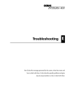
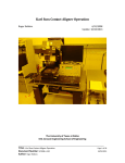
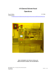
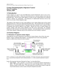
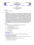
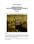
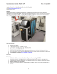
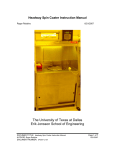
March Asher Operation Roger Robbins 7/31/2006 The University of Texas at Dallas Erik Jonsson Engineering School of Engineering ______________________________________________________________________ TITLE: March Asher Operation Page 1 of 13 Document Number: SU2006-TF-001 7/31/2006 March Asher Operation Roger Robbins 7/31/2006 C:\MyDocuments\CleanRoomGeneral\Equipment\MarchAsher\MarchAsherOperation.doc Table of Contents March Asher Operation ................................................................................................... 3 Introduction .................................................................................................................. 3 Tool Description ........................................................................................................... 3 Reaction Chamber ................................................................................................... 3 Process Controller Module ....................................................................................... 5 RF Power Generator ................................................................................................ 7 Tool Operation ............................................................................................................. 7 Initial Release Philosophy ........................................................................................ 7 Setting Process Parameters ..................................................................................... 8 Conclusion ................................................................................................................... 9 Appendix A.................................................................................................................... 10 Appendix B.................................................................................................................... 12 Appendix C ................................................................................................................... 13 ______________________________________________________________________ TITLE: March Asher Operation Page 2 of 13 Document Number: SU2006-TF-001 7/31/2006 March Asher Operation Roger Robbins 7/31/2006 C:\MyDocuments\CleanRoomGeneral\Equipment\MarchAsher\MarchAsherOperation.doc Introduction This is an interim manual for initial processing release of the PX-250 model March Asher system newly purchased for the UTD Clean Room. This is a highly versatile plasma etch tool that can etch using a direct plasma configuration, a downstream plasma, and a directional plasma (Reactive Ion Etch). Because it is so versatile, we plan to introduce it in stages. The first stage will be Oxygen ash of photoresist. However, even this process is quite complex due to the many resists and thicknesses used in the clean room. Therefore this manual will describe a procedure to set the process parameters for a general use default program, number “1.” The user will have freedom to input parameters to program “1” to handle his particular needs, but we will incorporate standard suggested starting parameters for common substrates and resulting etch rates later. Tool Description This tool is an RF plasma batch etcher designed to create three distinct types of plasma etch conditions. The three plasma types are achieved by adjusting the etch chamber shelves and loading samples onto specific shelves. The process is input through front panel buttons to a microprocessor which then controls the vacuum pump down, establishment and duration of the plasma, and venting back to atmosphere whereupon completion of the process is announced by a beeping enunciator. The tool consists of three parts: 1)a plasma chamber with interchangeable shelves that can be powered, grounded, or floating, 2) a control system for establishing the process flow, and 3) a separate solid state RF power generator which is controlled by the system microprocessor. Reaction Chamber The plasma reaction chamber is about one cubic foot in size and shape with 6 removable shelves seated on sidewall mounted ceramic support posts. The shelves are cleverly designed with electrode “tongues” on one of the rear corners that plugs into either a powered or grounded receiver socket, depending on whether the shelf is inserted right side up or upside down. This arrangement flexibility enables the establishment of the various plasma types. For example our initial configuration will establish a grounded upper shelf and a powered lower shelf for the substrate. This establishes an RIE configuration similar to our other little RIE plasma etcher so that the initial processes will be similar to the currently established ashing processes. Figure 1 shows the reaction chamber. ______________________________________________________________________ TITLE: March Asher Operation Page 3 of 13 Document Number: SU2006-TF-001 7/31/2006 Figure 1. March Asher plasma reaction chamber showing the thin aluminum shelves sitting on ceramic posts emanating from the walls. There is a glass window in the door enabling the user to see the etch progress. Note also that the door has a “storm door” attached to it to cover the window – this reduces the RF emissions and shields the UV light. Figure 2. Photo of the clever process shelves showing the Copper plug at one rear corner for connecting to RF power, or ground to change plasma type. Photos - Left to Right shelf configuration: Power, Ground, Neutral, Plug sockets at rear of plasma chamber. The shelves have a flat Copper male plug on one of the rear corners. If the plug is plugged into the left column of receptacles it will be RF powered, if plugged into the right column, it will be grounded. There is also a “floating” shelf without any electrodes. The shelf configuration can be changed by simply pulling the shelves out and rearranging them, ______________________________________________________________________ TITLE: March Asher Operation Page 4 of 13 Document Number: SU2006-TF-001 7/31/2006 The door latch is a bit peculiar, so note the operation in the photos below. Figure 3. Latch closing operation. The opening procedure is left to the user’s imagination. Process Controller Module The Process Controller monitors and controls the various parameters of the process. The basic ON/OFF portion of the control panel is shown in Figure 4. The parameter input and monitor panel is shown in Figure 5. Figure 4. Basic on/off portion of the control panel. The machine is switched on by pressing the medium sized green button. The big red emergency OFF button is used to turn off the machine. The Key is a lock-out for parameter change operations. For general use, the tool will not be locked. The “Auto/Man” switch enables manual RF tuning to match the plasma impedance with the output impedance of the RF generator. The Alarm beeps at the end of process and the volume knob sets the loudness of the enunciator. The alarm is silenced by pushing the “STOP” button in Figure 5. ______________________________________________________________________ TITLE: March Asher Operation Page 5 of 13 Document Number: SU2006-TF-001 7/31/2006 Figure 5. Parameter input and monitor panel on the upper left of the control panel. The parameter input section of the control panel, Figure 5, consists of 4 sections. The first is the START/STOP buttons, which do just that – start the automatic program or stop it. The second section, “PROGRAM,” is the program selection button. By repeatedly pushing this button you can cycle through all 9 possible programs. When a program is selected it is available for execution by the start button. Parameter input is achieved through the 8 buttons in the upper right section of the panel. The term “L DISP” denotes the “Left Display” lights above the buttons. If the “SET” button is pushed and the LED lights up, you can change the numbers by repeatedly pressing either the DECR or INCR buttons just below the SET button. The particular parameter you are selecting is set by repeatedly toggling the “LDISP” button until the corresponding label is lit. The third set of 4 buttons in the upper right selects the process gas by toggling the “RDISP” (Right Display) “SET” button, and sets the flow in units of “% of Mass flow meter capacity.” There are six gas sources that can be selected by repeatedly pressing the “R DISP” button. Currently we have only one gas available – “GAS 1” which is Oxygen. Pressure is determined by the flow rate as this tool has no vacuum level throttle valve control. Staff will provide a table to correlate pressure with gas flow – See Appendix A. The fourth set of buttons deals with manual operation. These are in the bottom row to the right of the “Manual” toggle button. These buttons are active when the “MAN OP.” light is on, and consist of the “VAC ON” button which toggles the vacuum valve on or off; the “PRESS” button which toggles a valve to expose the vacuum gauge to the vacuum line; the “GAS ON” valve, which toggles the process gas on or off; the “RF ON” button which toggles the RF power on or off; and the “BLEED” button, which pumps the chamber down to a minimum set point, then vents the chamber. CAUTION: Take care not to open the “PRESS” valve when the pressure gauge is at vacuum and the vacuum line is at atmospheric pressure. This will send a pressure shock wave into the vacuum diaphragm triggering a calibration drift and possibly causing damage to the gauge. The proper procedure is to open the valve and wait at least 15 seconds before opening the vacuum line to the gauge. ______________________________________________________________________ TITLE: March Asher Operation Page 6 of 13 Document Number: SU2006-TF-001 7/31/2006 RF Power Generator The RF power generator is a separate unit sitting just to the left of the asher system. It provides the 13.6 MHz RF power to drive the plasma. It is remotely controlled by the process controller microprocessor, therefore the buttons on the front panel of the RF generator are inactive but the power meter indicates the forward and reverse power delivered to the plasma chamber. This meter should indicate mostly forward power and very little reverse power. If you notice the reverse ratio shut off the plasma with the big red EMO button to protect the RF generator from overheating and contact a staff member. Figure 6. RF power generator front panel indicating forward (FWD) and reverse (REV) power. Tool Operation The following is a description of how to setup and operate the March Asher in the initially released mode of operation. This section will discuss inputting samples, program data, and switching to Auto operation to execute a process. Initial Release Philosophy Since the plasma process is a product of complex interacting process parameters and the substrate process requirements are diverse, we will have to set up a changeable process for users to set up whatever process they need. However in the beginning we will restrict this tool to Oxygen ashing processes in the RIE. This seems a logical transition philosophy because it allows an almost one to one transfer of previous Technics RIE processes to the new reactor. However, it also implies that the time, power and pressure must remain variables settable by the user. Therefore it is our intention to allow free parameter input, but we will require that the various programs be run in the automatic mode. The user will input his parameter values into the default program #1 and actually run it in the automatic mode. The reason for this is to prevent runaway processes which may heat up the (un-cooled) substrate shelves to a dangerous temperature, possibly causing damage to the substrate or pose a burn danger to users. ______________________________________________________________________ TITLE: March Asher Operation Page 7 of 13 Document Number: SU2006-TF-001 7/31/2006 Setting Process Parameters The following description is a brief explanation of how to set up the process parameters. PROGRAMMING Press the “PROGRAM” button until program “1” appears in the window above the PROGRAM label. Press the “L DISP” button repeatedly until the “TIME” label lights up o Press the “SET” button to illuminate its LED light o Press the “DECR or INCR” buttons to set the plasma “on” time (sec) by decreasing or increasing the time in the left display above. o When the correct time appears in the display, press the “SET” button again to extinguish the LED light. This saves the value. Press the “L DISP” button to light up the “POWER” label. o Press the “SET” button to illuminate its LED light o Press the “DECR or INCR” buttons to set the plasma power (Watts) by decreasing or increasing the Power in the left display above. o When the correct power appears in the display, press the “SET” button again to extinguish the LED light. This saves the value. Press the “R DISP” button on the right side to illuminate the “GAS1” label. o Press the “SET” button to illuminate its LED light o Press the “DECR or INCR” buttons to set the O2 flow rate, (% of 100 sccm), by decreasing or increasing the value in the right display above. o When the correct flow value appears in the display, press the “SET” button again to extinguish the LED light. This saves the value. o Consult the percent O2 flow vs pressure chart in Appendix B to determine the proper flow value for your process pressure. The actual values may drift somewhat over time as the vacuum pump oil becomes contaminated, so some variance from the table may be required as experience dictates. INSERTING THE SUBSTRATE Press the “MAN OP” button and then press the “BLEED” button to vent the chamber. When the chamber is vented, unlatch the chamber door and insert sample. o For the recommended RIE process condition, set your sample on the RF powered shelf below a grounded shelf – see chamber labels. o Close and latch the chamber door. o Press the “MAN OP” button again to activate the automatic operation mode (“MAN OP” LED light is extinguished for auto operation). RUNNING THE PROCESS Select Program 1 if it is not already indicated by pressing “PROGRAM” button until #1 appears in the display. Press the “START” button in the upper left corner This starts the process: ______________________________________________________________________ TITLE: March Asher Operation Page 8 of 13 Document Number: SU2006-TF-001 7/31/2006 o o o o o o o Chamber is pumped down to 70 millitorr Gas flow is started RF Power is turned on – Note the forward and reflected power values on the RF power supply to the left of the process control module. If the reverse power is more than 50%, shut off the system with the BIG RED EMO button and call a staff member. Time counts down from your set value At the conclusion of the time, the RF power and Gas flow are turned off and the chamber is pumped down to base pressure. After achieving base pressure, the chamber is vented with Nitrogen for 45 seconds. At the conclusion of the vent cycle, a beeper peeps softly. RETREVING YOUR SUBSTRATE At the end of the vent cycle, shut off the beeper by pressing the “STOP” button. Open the door and retrieve your sample. Be careful to note the temperature of the substrate shelf as it can get hot on long runs. When the sample is out, close and latch the chamber door Press the “MAN OP” button and the “VAC ON” button to pump the chamber down again. Allow the vacuum to achieve base pressure and then shut off the “VAC ON” valve. Conclusion This manual has described the basic operating procedures for the initial Oxygen Ash process release condition for the PX250 March Asher. As time goes on and our experience level builds up, more types of processes may be allowed. Note that we have included several appendices to present initial processing information and suggested process flows. ______________________________________________________________________ TITLE: March Asher Operation Page 9 of 13 Document Number: SU2006-TF-001 7/31/2006 Appendix A Chamber Pressure vs Gas Flow Rate Use this chart to decide what approximate gas flow is needed to establish the pressure you need for your plasma. You may have to fine adjust the flow to achieve accurate pressure. As time goes on, the base pump pressure may degrade and shift the lower end of this correlation curve somewhat. Argon mass flow controller maximum flow is 250 sccm, and the Oxygen meter is 100 sccm – thus the large difference in pressure curves. ______________________________________________________________________ TITLE: March Asher Operation Page 10 of 13 Document Number: SU2006-TF-001 7/31/2006 Actual Flow Rate vs Flow Setting This chart calibrates the flow setting to actual flow in units of Standard Cubic Centimeters per Minute (sccm). The Argon Mass Flow Controller maximum flow is 250 sccm, and the Oxygen meter is 100 sccm – thus the large difference in pressure curves. ______________________________________________________________________ TITLE: March Asher Operation Page 11 of 13 Document Number: SU2006-TF-001 7/31/2006 Appendix B Process 1 2 3 4 Initial O2 Ashing Rates for Photomask AZ1518 Resist RF Power O2 Flow Pressure (Watts) (% of 100 sccm) (mTorr) 250 20 178 250 30 230 250 75 603 Etch Rate (A/Min) 2106 2272 2165 This is an initial process result using 250 Watts of RF power on a 2 micron thick film of AZ1518 (resist used on common photomasks). The film thickness etch rate was determined by measuring the untreated thickness and subtracting the thickness remaining after 5 minutes of plasma treatment. ______________________________________________________________________ TITLE: March Asher Operation Page 12 of 13 Document Number: SU2006-TF-001 7/31/2006 Appendix C Leak-back Rate This graph shows several measurements of Leak-back Rate as a function of time. The top curve represents a high leak-back rate developed over two years of use without correction. The middle line represents the leak-back after fixing several leaks in the system that developed over a long time. The bottom curve represents the leak-back after cleaning the chamber by running a high power Oxygen plasma for about a half hour to clean moisture absorbing organics off of the walls. ______________________________________________________________________ TITLE: March Asher Operation Page 13 of 13 Document Number: SU2006-TF-001 7/31/2006