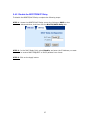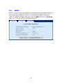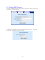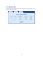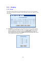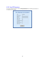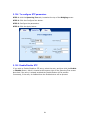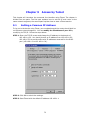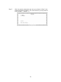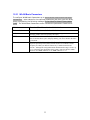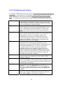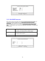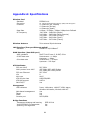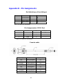
1
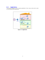
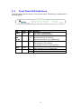
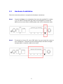
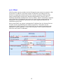
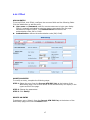
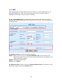
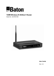
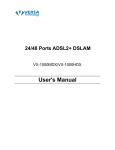
CT-535 Wireless ADSL Router User’s Manual Version A1.1, May 22, 2003 261035-009 i Preface It is designed to provide information to network administrators. It covers the installation, operation and applications of the Wireless ADSL Router Warning Before servicing or disassembling this equipment, always disconnect all power and telephone lines from the wall outlet. Use an appropriate power supply and a UL Listed telephone line cord. Specification of the power supply is stated in Appendix A Specifications. ii TABLE OF CONTENTS CHAPTER 1 1.1 1.2 1.3 1.4 CHAPTER 2 2.1 2.2 CHAPTER 3 3.1 3.2 CHAPTER 4 4.1 4.2 4.3 4.4 4.4.1 4.4.2 4.4.3 4.4.4 4.4.5 4.5 4.6 4.6.1 4.6.2 4.6.3 4.6.4 4.7 4.7.1 4.7.2 4.8 4.9 4.10 INTRODUCTION ............................................................1 Overview............................................................................................ 1 Features .............................................................................................. 2 Application......................................................................................... 3 Front Panel LED Indicators ............................................................... 4 INSTALLATION .............................................................5 Preparing for Hardware Installation................................................... 5 Hardware Installation......................................................................... 6 LOGIN VIA THE WEB BROWSER ....................................9 IP Address.......................................................................................... 9 Login Procedure............................................................................... 10 WEB BASIC CONFIGURATION......................................11 Version Information......................................................................... 11 Change the Password ....................................................................... 11 ADSL Link Status............................................................................ 12 WAN Setup...................................................................................... 13 RFC 1483 Bridged ........................................................................... 13 RFC 1483 Routed ............................................................................ 14 PPPoE .............................................................................................. 15 PPPoA .............................................................................................. 17 MER................................................................................................. 18 LAN IP Address............................................................................... 19 WLAN Configuration ...................................................................... 20 WLAN Basic Parameters................................................................. 21 WLAN Advanced Functions............................................................ 22 WLAN WEP Parameters: ................................................................ 24 Mac Filter......................................................................................... 25 Routing............................................................................................. 26 Enable RIP ....................................................................................... 27 Static route configuration................................................................. 28 Save.................................................................................................. 30 Reboot .............................................................................................. 31 Retrieve default settings................................................................... 32 iii CHAPTER 5 5.1 5.2 5.3 5.3.1 5.3.2 5.3.3 5.3.4 5.4 5.4.1 5.4.2 5.5 5.5.1 5.5.2 5.5.3 5.6 5.6.1 5.6.2 5.6.3 5.7 5.7.1 5.7.2 5.8 5.8.1 5.8.2 5.8.3 5.9 5.9.1 5.9.2 5.9.3 5.9.4 5.9.5 5.9.6 5.10 5.11 5.11.1 5.11.2 5.12 WEB ADVANCED CONFIGURATION ..............................33 ADSL Mode..................................................................................... 33 VLAN .............................................................................................. 33 DHCP............................................................................................... 34 Enable DHCP................................................................................... 34 Disable DHCP.................................................................................. 34 Add a DHCP Entry .......................................................................... 35 Disable DHCP.................................................................................. 35 DHCP Relay..................................................................................... 36 Enable the DHCP Relay................................................................... 36 Disable the BOOTP/DHCP Relay ................................................... 37 SNMP............................................................................................... 38 Modifying SNMP Parameters.......................................................... 39 Modifying Traps .............................................................................. 40 Modifying Communities.................................................................. 41 Firewall ............................................................................................ 42 Enable/Disable the Firewall............................................................. 42 View Firewall Actions ..................................................................... 43 IP Filtering ....................................................................................... 43 NAT ................................................................................................. 45 Static NAT Mapping........................................................................ 45 Static Port Mapping ......................................................................... 46 Configure ......................................................................................... 47 Configure Interface .......................................................................... 48 DNS & Default Gateway ................................................................. 49 NAT ................................................................................................. 50 VCC ................................................................................................. 51 List IPoA.......................................................................................... 51 Delete Encapsulation ....................................................................... 52 Add a VCC....................................................................................... 53 Delete a VCC ................................................................................... 55 Show VCC quality ........................................................................... 55 PPPoE .............................................................................................. 55 PPPoA .............................................................................................. 56 IGMP................................................................................................ 56 Add an IGMP entry.......................................................................... 57 Delete an IGMP entry ...................................................................... 57 Bridging ........................................................................................... 58 iv 5.12.1 5.12.2 5.12.3 5.12.4 5.12.5 5.13 5.13.1 5.13.2 5.13.3 5.13.4 5.13.5 CHAPTER 6 6.1 6.2 6.2.1 6.2.2 6.2.3 6.3 6.3.1 6.3.2 CHAPTER 7 7.1 7.2 Bridge............................................................................................... 58 Spanning tree ................................................................................... 59 View STP Parameters ...................................................................... 60 To configure STP parameters .......................................................... 61 Enable/Disable STP ......................................................................... 61 Filtering............................................................................................ 62 List of filter entries........................................................................... 62 Add a filter entry.............................................................................. 63 Delete a filter entry .......................................................................... 63 Modify a filter entry......................................................................... 63 Flush filter entries ............................................................................ 63 WEB PERFORMANCE MONITORING..............................64 ADSL Link Status............................................................................ 64 System Statistics .............................................................................. 65 Interface Statistics ............................................................................ 65 TCP-IP ............................................................................................. 66 DHCP-Lease .................................................................................... 66 ATM statistics.................................................................................. 67 AAL5 ............................................................................................... 67 Encapsulation................................................................................... 67 WEB DIAGNOSTICS.....................................................68 OAM Loopback ............................................................................... 68 Ping .................................................................................................. 69 CHAPTER 8 FIRMWARE UPGRADE..................................................70 CHAPTER 9 ACCESS BY TELNET .....................................................72 9.1 9.2 CHAPTER 10 10.1 10.2 10.3 10.3.1 10.3.2 10.3.3 Setting a Common IP Address......................................................... 72 Telnet Access ................................................................................... 73 CONSOLE MANAGEMENT .............................................74 Hardware connection ....................................................................... 74 Access by Console ........................................................................... 74 Console WLAN Guide..................................................................... 76 WLAN Basic Parameters................................................................. 77 WLAN Advanced Functions............................................................ 78 WLAN WEP Parameters: ................................................................ 79 APPENDIX A: SPECIFICATIONS ..........................................................80 APPENDIX B - PIN ASSIGNMENTS ......................................................82 v Chapter 1 1.1 Introduction Overview The wireless ADSL router combines cutting-edge wireless technology with routing/bridge functions. It enables multiple users to share a high speed ADSL connection, without connecting any wires. To ensure the security of your valuable data the router employs state-of-the-art security features such as WEP data encryption, L2TP, and IpSec pass through. To provide maximum immunity from broadband interference the router incorporates the latest wireless modulation technology (DSSS). The router is designed for residential and business users who need wireless access through an ADSL router. In addition to wireless connectivity, the wireless ADSL router has four 10/100 Base-T Ethernet ports for LAN connection. It can access the Internet, Corporate LAN, or Video on Demand over one ordinary telephone line, and establish up to 8 concurrent virtual-connections to multiple destinations. 1 1.2 Features The Wireless ADSL Router has the following features: Wireless built-in ADSL router IEEE 802.11b compliance 11Mbps/5.5Mbps/2Mbps/1Mbps data rates with auto-fallback support WEP data encryption Four 10/100 Base-T Ethernet ports for LAN connection Bridge/Router AAL5 for ATM over ADSL UBR/CBR/VBR ATM services VC-based and LLC multiplexing Up to 8 VCs Embedded SNMP agent and RFC MIB II Web-based management OAM F4 and F5 Static route/RIP/RIP v2 routing Dynamic IP assignment and Network Address Translation 2 1.3 Application The following diagram shows a typical application of the router, which can be used for G.lite and G.DMT applications. Figure 1-1 Application 3 1.4 Front Panel LED Indicators The front panel LEDs are shown in the picture below, followed by an explanation in the table below. LED Power Color Green Green LAN 1x~4x WLAN Green ADSL Green ALARM Red Mode On Off On Blink Off Blink Off On On Off On Off Function The router is powered up The router is powered down. Ethernet connection is established. Data transmitting or receiving Ethernet connection is not established. Data transmitting or receiving over WLAN The wireless is not installed. The wireless module is ready and idle. The ADSL connection is established. ADSL connection is not established. The ADSL link is terminated. Normal operating status 4 Chapter 2 2.1 Installation Preparing for Hardware Installation The following equipment may be necessary to install the router: AC power adapter A suitable power adapter is shipped with the router. It is used to provide the necessary power for the router’s operation. LAN connection cable To connect to a hub or PC, use an RJ45 cable. RJ11 cable An RJ11 cable is needed to connect to the LINE port. Optional micro filter and POTS splitter If you wish to connect both the router and a telephone, you will need the optional micro filter or POTS splitter. 5 2.2 Hardware Installation Follow the instructions below to complete the hardware connections. Step 1 Connect the Line port to a telephone-line using the supplied RJ-11 cable; or if you wish to connect both the router and a telephone, connect the ADSL port to a micro filter or POTS splitter with a RJ11 connection cable. Step 2 To connect to a hub or PC, use a RJ45 cable. You can connect the router to four LAN devices. The ports are auto-sensing MDI/X and either straightthrough cable or crossover cable can be used. 6 Step 3 (Optional) In order to manage your device through the console port you will need to use a straight-through cable with an RJ-45 connector to attach to the modem, and a female RS-232 connector to connect to the serial port on a PC. The PC must be equipped with a VT-100 emulation program, such as HyperTerminal 5 or Telix. Step 4 Connect the Power jack to the shipped power cord. 7 Step 5 Attach the power adapter to the wall outlet or other AC source. Step 6 After all connections have been made, turn the power-switch to the on position. After power on, the router performs a self-test. Wait for a few seconds until the test is finished, then the router will be ready to operate. Caution 1: If the router fails to power up, or it malfunctions, first verify that the power supply is connected correctly. Then power it on again. If the problem persists, contact our technical support engineers. Caution 2: Before servicing or disassembling this equipment always disconnect all power cords and telephone lines from the wall outlet. 8 Chapter 3 Login via the Web Browser This section describes how to manage the router via a Web browser from the remote end. You can use a web browser such as Microsoft Internet Explorer, or Netscape Navigator. It is best to set your display resolution to 1024 x 768. To change the resolution you can go to the Microsoft Windows control panel and click on the Display icon, and change the display settings. You will find the display settings there. 3.1 IP Address To log on to the device using a web browser, your workstation and the device should both be on the same network segment. STEP 1: Enter the TCP/IP screen and change the IP address to the domain of 192.168.1.x/24. You should choose an IP address from 192.168.1.132192.168.1.254 to avoid conflict with IP addresses reserved for the DHCP pool (192.168.1.3 to 192.168.1.131). STEP 2: Click OK to submit the settings. STEP 3: Start your Internet browser with the default IP address 192.168.1.1. 9 3.2 Login Procedure To log on to the system from the Web browser, follow the steps below: STEP 1: Start your Internet browser. STEP 2: Type the IP address for the router in the Web address field. For example, if the IP address is 192.168.1.1, type http://192.168.1.1 STEP 3:You will be prompted to enter your user name and password. Type the password, or if the password was not changed, type the default passwords. The default USER name is root, and the default password is 12345 (some versions require a login of 1234). STEP 4:After successfully logging in, you will reach the main menu. 10 Chapter 4 Web Basic Configuration From the Basic menu bar, you can verify the software version, change passwords, configure the WAN/LAN interfaces, set-up routing, save settings, reboot the device, and retrieve the factory default settings. 4.1 Version Information To verify the software version of your router, from the Basic Menu bar, click on Version Information. The information will display as in the screenshot below. 4.2 Change the Password To modify the password, click Change Password from the menu bar. Type the old password and type the new password twice. Click Apply to submit the settings. If you change the password, make sure you keep a record of it in a safe place, as you will require it next time you log-on. 11 4.3 ADSL Link Status To view the ADSL link status, click Link Status from the tool bar. The page includes the following information: ADSL Line Status Shows the current status of the ADSL line ADSL Mode Shows the ADSL standard that is currently configured. The standards are: ANSI, G.DMT, G.LITE, MULTI. Upstream Upstream data rate negotiated by DSL link (Kbit/s) Downstream Downstream data rate negotiated by DSL link (Kbit/s) Attenuation Current attenuation (dB) of both near end and far end. SNR Margin Current SNR margin (dB) HEC Number of ATM cells received with errors, since start of link. Firmware The version number of the firmware 15 min ES counter Number of errored seconds for the current 15 minute period CRC errors Number of errors per second since training 1 day ES counter Number of errored seconds for the current day 12 4.4 WAN Setup Click WAN Setup from the tool bar and configure the WAN interface for these services: RFC1483 Bridged, RFC1483 Routed, PPPoE, PPPoA, and MER. The following are the common settings to set up these services. VPI and VCI LLC Encapsulation: With LLC encapsulation, a link control header is added to the Ethernet packet that identifies the protocol type (Ethernet). This allows multiple protocols to be transmitted over the ATM Virtual Circuit. VC Multiplexing: With VC Multiplexing, no link control header is needed as the ATM Virtual Circuit is assumed to be carrying a single protocol. Enable NAPT: NAPT or Network Address Port Translation, enables the translation of private and public addresses. This feature is available for RFC 1483 Routed, PPPoE, PPPoA, and MER. It is enabled for PPPoE. 4.4.1 RFC 1483 Bridged When using RFC 1483 style bridging, Ethernet frames are “bridged” over ATM Virtual Circuits. The Ethernet frames are encapsulated using either LLC Encapsulation or VC Multiplexing. With LLC encapsulation, a link control header is added to the Ethernet packet that identifies the protocol type (Ethernet). This allows multiple protocols to be transmitted over the ATM Virtual Circuit. With VC Multiplexing, no link control header is needed as the ATM Virtual Circuit is assumed to be carrying a single protocol. Since the Ethernet packets are bridged, the router’s only responsibility is to pass the Ethernet packets to and from the Internet Service Provider and the local network. The IP addresses of the local network are assigned by the ISP either statically or dynamically. ADD AN ENTRY To set up the RFC 1483 Bridged, configure the common fields on the top of the page and click the Add button to add the entry. MODIFY AN ENTRY To modify an entry, complete the following steps: STEP 1: Select the entry from the Current ATM PVC List, at the bottom of the WAN Setup page. The current values of the selected entry will display in the upper section of the page. STEP 2: Change the parameters. STEP 3: Click Modify. 13 DELETE AN ENTRY To delete an entry, Select it from the Current ATM PVC List, at the bottom of the WAN Setup page, and click the Delete button. 4.4.2 RFC 1483 Routed ADD AN ENTRY To set up the RFC 1483 Routed, configure the common settings on the top of the page, click RFC 1483 Routed and configure the specific settings (WAN IP address and WAN subnet mask). Click the Add button to add the entry. MODIFY AN ENTRY To modify an entry, complete the following steps: STEP 1: Select the entry from the Current ATM PVC List, at the bottom of the WAN Setup page. The current values of the selected entry will display in the upper section of the page. STEP 2: Change the parameters. STEP 3: Click Modify. DELETE AN ENTRY To delete an entry, Select it from the Current ATM PVC List, at the bottom of the WAN Setup page, and click the Delete button. 14 4.4.3 PPPoE PPPoE provides service providers similar billing and access control as present in dialup services. In addition, with direct support to Ethernet it provides a low cost solution to supporting multiple hosts at the customer premises. PPPoE provides session authentication using either Password Authentication Protocol (PAP) or Challenge Handshake Authentication Protocol (CHAP). Session accounting is possible and conservation of bandwidth can be done by closing down unused sessions. By utilizing PPP, link and network parameters are easily negotiated between the IAD/Router and the ISP. When using PPPoE, the system is assigned an IP address from the Internet Service Provider as part of establishing the network connection. The system can be configured as a DHCP server for its LAN and NAT can be used to translate private addresses to public addresses. In this way, computers in the LAN do not have to have their own public IP addresses. 15 ADD AN ENTRY To set up PPPoE, click PPPoE, configure the common fields on the top of the page, as well as the following fields. At the bottom of the screen, click the Add button to add the entry. In addition, If the PPPoE mode is set to auto, clicking the MANUAL MODE Enable button will effectively disable auto mode, and require the user to reconnect a terminated PPPoE session by clicking the MANUAL MODE Trigger button. Subsequently, to return to Auto-mode, click on the MANUAL MODE Disable button, which will appear in place of the MANUAL MODE Enable button. User name/Password: used for the remote customers to login during dialup. Mode: Direct and Auto. If the mode is set to AUTO, the PPPoE negotiation automatically starts when the system identifies any traffic required to be transferred on the link. When DIRECT is selected the PPPoE negotiation is started manually using the “pppoestart” command. The default is DIRECT. Idle Timeout: defines the period of idle time (minutes) after which the PPPoE link will be terminated. Authentication: defines the authentication code: PAP, and CHAP Enable DHCP Server: enables the DHCP server. This field is automatically checked when PPPoE is selected. Deselect the field to disable the DHCP server. The DHCP server dynamically allocates network addresses and delivers configuration parameters to hosts. MODIFY AN ENTRY To modify an entry, complete the following steps: STEP 1: Select the entry from the Current ATM PVC List, at the bottom of the WAN Setup page. The current values of the selected entry will display in the upper section of the page. STEP 2: Change the parameters. STEP 3: Click Modify. DELETE AN ENTRY To delete an entry, Select it from the Current ATM PVC List, at the bottom of the WAN Setup page, and click the Delete button. 16 4.4.4 PPPoA ADD AN ENTRY To set up PPPoA, click PPPoA, configure the common fields and the following fields. Click the Add button to add the entry. User name and Password: used for remote customers to login upon dialup. PPPoA is manually activated by entering startup commands from the page: Advanced>Configure PPPoA. The Authentication field defines the authentication code: PAP or CHAP. Authentication: defines the authentication code (PAP, CHAP). MODIFY AN ENTRY To modify an entry, complete the following steps: STEP 1: Select the entry from the Current ATM PVC List, at the bottom of the WAN Setup page. The current values of the selected entry will display in the upper section of the page. STEP 2: Change the parameters. STEP 3: Click Modify. DELETE AN ENTRY To delete an entry, Select it from the Current ATM PVC List, at the bottom of the WAN Setup page, and click the Delete button. 17 4.4.5 MER MAC Encapsulation Routing (MER) enables the ATU-R to route IP addresses on the RFC1483 bridged link. NAPT function is supported to allow multiple private IP addresses on the LAN to share a public IP address. To set up the MER service, configure the common fields, and then enter the IP Address and Subnet Mask under the MER section of the screen. Click the Add button to add the entry. To modify an entry, complete the following steps: STEP 1: Select the entry from the Current ATM PVC List, at the bottom of the WAN Setup page. The current values of the selected entry will display in the upper section of the page. STEP 2: Change the parameters. STEP 3: Click Modify. To delete an entry, Select it from the Current ATM PVC List, at the bottom of the WAN Setup page, and click the Delete button. 18 4.5 LAN IP Address Click LAN Setup from the menu bar to configure the LAN IP address. Type the IP address and subnet mask. Click Apply to submit the settings. When the new IP address is applied, the Web configuration will be interrupted. Use the new IP address to login. 19 4.6 WLAN Configuration Parameters that specifically deal with the wireless functions of your router can be accessed from WLAN Setup on the Basic menu bar. The menu is subdivided into three menus: WLAN Basic, WLAN Advanced, and WLAN WEP. Each of these menus will be covered below. 20 4.6.1 WLAN Basic Parameters To access the WLAN Basic parameters click on the WLAN Basic tab on the WLAN Settings screen. The WLAN Basic Parameters menu includes the parameters listed below. After changing any parameters, click on the Apply button to update the parameters, or click on the Restore button to retain the original settings. IP Address Subnet Mask SSID Channel Enter the IP address for the WLAN interface Enter a subnet mask for the WLAN interface The SSID should match with your client adapters. The SSID (Service Set ID) allows you to uniquely identify your Access Point in the radio environment. The channel should match with client adapters. The Direct Sequence Spread Spectrum (DSSS) channel number is an identifier for the frequency on which your WLAN connectivity is enabled in the WLAN network. Although the configurable DSSS channel number range is from 1 up to 14, restrictions apply depending on the country where the Wireless ADSL-Router is used: FCC: channels 1 to 11 ETSI: channels 1 to 13. 21 4.6.2 WLAN Advanced Functions To access the WLAN Advanced parameters click on the WLAN Advance tab on the WLAN Settings screen. The WLAN Advanced Parameters menu includes the parameters listed below. After changing any parameters, click on the Apply button to update the parameters, or click on the Restore button to retain the original settings. Beacon Interval RTS Threshold Fragmentation DTIM Interval Preamble Type Auth. Type Tx Rates Specify the Beacon Interval value. Enter a value between 1 and 1000. The value represents the time in nano-seconds that Beacon packets are sent by an Access Point to synchronize a wireless network. This value should normally remain at its default setting of 2,432. Should you encounter inconsistent data flow, only minor modifications are recommended. The value must match with remote clients. This field is used to specify the fragmentation threshold. Enter a value between 256 and 2346. If you experience a high packet error rate, try to slightly increase your Fragmentation Threshold. The value should normally remain at its default setting of 2,346. This value must match client adapters. Enter a value between 1 and 65535. This number represents the time between sending delivery traffic identification messages (DTIMs) used for power saving and multicast/broadcast delivery. A DTIM is a countdown informing clients of the next window for listening to broadcast and multicast messages. When the AP has buffered broadcast or multicast messages for associated clients, it sends the next DTIM with a DTIM Interval value. AP Clients hear the beacons and awaken to receive the broadcast and multicast messages. long, short . Should match client adapters. Short enables faster throughput, but it can only be used when all network elements comply with the IEEE 802.11b standard. Open System [no security], Shared Key [select this option if you wish to enable WEP security], if you select both, then both Open System and Shared Key will be simultaneously enabled. The transfer rate of the router should be equal to or greater than the clients, the options are: 1-2-5-11 (Mbps). 22 23 4.6.3 WLAN WEP Parameters: To access the WLAN WEP parameters click on the WLAN WEP tab on the WLAN Settings screen. This screen is used to set-up WEP security. WEP security uses an encryption keyword on all transmitted and received data. The parameters are described below. After changing any parameters, click on the Apply button to update the parameters, or click on the Restore button to retain the original settings. Key Type Disabled, 64 bits, 128 bits. This parameter determines the level of security. Disabled means no security, 128 bits provides the highest security. This parameter must match with the remote-clients. Key Generation Select Passphrase to enable automatic key generation, or Manual to manually enter each key Passphrase Enter a Passphrase if you wish clients to require a Passphrase to connect with the access point. KeySelect Select a Key from 0~3. This key will be the active hexadecimal password for access. If you are using a manual Passphrase enter a hexadecimal password for each key. This hexadecimal password will be required to be set on any wireless client that you wish to connect with your access point. Key 0~3 24 4.6.4 Mac Filter This screen allows access to be restricted/enabled based on a MAC address. Enter the following parameters and then click the Add button. MAC address: Enter the MAC address of the access point. Auth Type: enter Open System to allow unrestricted access to the access point, or Share Key to require confirmation with the parameters of the WEP security keys (Click the WEP tab to verify these settings). To delete an entry select the entry at the bottom of the screen and then click the Delete button, located in the middle of the screen. 25 4.7 Routing Click Routing Setup from the menu bar to configure the routing functions. Routing functions includes RIP and static routing. You can display the RIP information by clicking the RIP information button. 26 4.7.1 Enable RIP To enable the RIP, complete the following steps: STEP 1: Click Routing Setup from the menu bar STEP 2: Select On in the Rip Status field. STEP 3: Select a RIP Version (Version 1 or Version 2) from the Version field. STEP 4: Click Apply to submit the settings. 27 4.7.2 Static route configuration The Routes Configuration field allows you to add, modify, and delete a static route. Type the Destination Network ID, subnet mask, and next hop IP and click a button below to perform the requested function. 28 Add: To add a static route complete the following steps: STEP 1: Click Routing Setup from the menu bar. STEP 2: Enter parameters for Destination Network ID, Subnet Mask, Next Hop IP, and Next Interface (note you must select between entering a Next Hop IP or Next interface). STEP 3: Click the ADD button. Modify: To modify a static route complete the following steps: STEP 1: Select the entry you wish to modify from the List of Static Routes. STEP 2: Change the parameters. STEP 3: Click the Modify button. Delete: STEP 1: Select the entry you wish to delete from the List of Static Routes STEP 2: Change the parameters. STEP 3: Click the Delete button. 29 4.8 Save To save the settings to Flash, click Save & Reboot from the menu bar. In the main pane, click Save. 30 4.9 Reboot To reboot the router, click Save & Reboot from the menu bar. In the main pane, click on Reboot. 31 4.10 Retrieve default settings To retrieve the default settings, click Erase & Reboot from the menu bar. In the main pane, click Erase. 32 Chapter 5 5.1 WEB Advanced Configuration ADSL Mode The ADSL modes are: ANSI, G.DMT, G.LITE, MULTI. MULTI mode enables the device to auto-adjust its mode to match the remote CO DLSAM. You can specify an ADSL mode on this page, and click the Apply button to submit the settings. 5.2 VLAN To configure the VLAN function, click VLAN from the Advanced menu bar. VLAN is disabled by factory default. To enable it, tick Enable and click the Set button. Then you can proceed to create the VLAN groups. The ATU-R supports four VLAN groups, VLAN groups 1 to 4. You can choose and join different Ethernet ports to the PVC running in RFC 1483 bridged mode. Packets will be transmitted or received from these ports to the appointed PVC. The packets of the VLAN groups are not routable. Packets that don’t belong to the VLAN group are routable. Parameters and buttons The PVC field displays the options of the PVCs set up in RFC 1483 Bridged mode (refer to section 5.4, WAN Setup). Click the Set button to apply the settings, or click the Clear button to delete a VLAN group. 33 5.3 DHCP The Dynamic Host Configuration Protocol (DHCP) provides a centralized approach to allocating IP addresses. It allows IP addresses to be dynamically assigned on an as needed basis, from a pool of addresses. The DHCP function of the device is disabled by factory default. 5.3.1 Enable DHCP STEP 1: Click the DHCP tab. STEP 2: Chose the entry and click the Start button 5.3.2 Disable DHCP STEP 1: Click the DHCP tab. STEP 2: Chose the entry and click the Stop button 34 5.3.3 Add a DHCP Entry To add an entry, click the Add button, and fill out the following parameters. Click Apply to submit the settings. Interface: eth0 only. This displays the interface that will provide the DHCP function. Starting IP Address: The first IP address of the address pool in the DHCP server. Note the IP address should be in the same subnet as the router’s LAN IP address. End IP Address: The last IP address of the address pool in the DHCP server. Note the IP address should be in the same subnet as the router’s LAN IP address. Gateway: The gateway IP address Netmask: The subnet mask of the IP network DNS: The IP address of the Domain Name Server Lease Time (in Days): Upon login, the remote workstation will obtain an IP address. This field defines the period of time that the workstation can use this IP address to access the Internet. 5.3.4 Disable DHCP STEP 1: Click DHCP from the menu bar. STEP 2: Choose a DHCP entry, and click Delete. 35 5.4 DHCP Relay The DHCP packet format is based on a BootP packet. As a result, DHCP uses the BootP relay agent to forward DHCP packets. This scheme provides interoperability between existing BootP clients and DHCP servers. The BootP relay agent uses the same criteria and methods for forwarding both DHCP and BootP packets. The DHCP Relay is disabled by default. 5.4.1 Enable the DHCP Relay To enable the BOOTP/DHCP Relay complete the following steps: STEP 1: Access the BOOTP/DHCP Relay screen by clicking on DHCP on the Advanced Menu, and then click the DHCP Relay tab. STEP 2: In the DHCP Relay field, select Enable, and enter the IP Address you want to receive BOOT REQUEST or DHCP packets from clients. STEP 3: Click on the Apply button. 36 5.4.2 Disable the BOOTP/DHCP Relay To disable the BOOTP/DHCP Relay complete the following steps: STEP 1: Access the BOOTP/DHCP Relay screen by clicking on DHCP on the Advanced Menu, and then click the BOOTP/DHCP Relay tab. STEP 2: In the DHCP Relay field, select Disable, and enter the IP Address you want to receive BOOT REQUEST or DHCP packets from clients. STEP 3: Click on the Apply button. 37 5.5 SNMP SNMP is a software entity that responds to information and action request messages sent by a network management station. The messages exchanged enable you to access and manage objects in an active or inactive (stored) MIB on a particular router. To configure the SNMP parameters, click the SNMP button on the Advanced menu bar. The window displays the SNMP parameters. 38 5.5.1 Modifying SNMP Parameters To modify the SNMP parameters, click the Modify button at the bottom of the screen. Click Apply to submit the settings. To configure the SNMP agent, click the Configure SNMP Agent button. After filling out the fields, click Apply to submit the settings. 39 5.5.2 Modifying Traps Click the Traps tab to configure the traps. After filling out the parameters, click Submit to apply the settings. 40 5.5.3 Modifying Communities Click the Communities tab to display the community entry. After filling out the parameters, click Submit to apply the settings. There is no community set up by factory default. To add or modify an entry, click the Configure Community button. To delete an entry, tick the entry and click the Delete button. The following screen displays after clicking the Configure Community button. Enter the parameters and ten click the Apply button. 41 5.6 Firewall The ADSL router provides packet filtering and stateful packet inspection, it has denial of service protection against attacks such as ICMP Flood, Ping of Death, IP spoofing, Port Scans, Land Attack, Tear Drop Attack, IP Source Route and WinNuke Attack. To access the firewall functions, select Firewall from the advanced menu. The screen will display as below, showing a list of the currently configured filter entries. From the Firewall page, you can turn the Firewall Mode On or Off, view Filter Parameters, add a filter, delete a filter, or View Action for filtered packets. Each of theses actions will be discussed below. 5.6.1 Enable/Disable the Firewall To enable the firewall click on the Enable/Disable tab on the Firewall screen and then check the Firewall Enable box and click the Apply button. Conversely, to disable the firewall uncheck the Firewall Enable box and click the Apply button. 42 5.6.2 View Firewall Actions Click View Actions to display the list of currently configured firewall actions. The parameters are as follows: Action ID: Item number Interface: The interface the filtering rule is created on. Firewall Action: The action taken when packets are received that correspond to a filtering rule. Allow will permit packets to pass through the router, Deny will drop corresponding packets. Reject will reject packet with a response, e.g., sending a TCP reset. Reset rejects a packet with a reset flag. 5.6.3 IP Filtering On the Firewall menu, click Add to configure the IP filtering entries. Fill out the parameters below and click Apply to submit the settings. The parameters are as follows: Policy Parameters: Precedence: This number sets the priority level of the rule, smaller numbers have higher priorities, if a conflict between rues occurs, enter a number from 1-65534. Src IP Address: Source IP address of the packet. Src Net Mask: Source Netmask of the packet. Dest IP address: Destination IP address of the packet. Dest Net Mask: Destination Net mask of the packet. Source Port: Source port of the packet (only for TCP/UDP protocol) Destination Port: Destination port of the packet (only for TCP/UDP protocol) Protocol: Select the protocol from the following: Any, TCP, UDP, ICMP, GRE, AH, ESP TCP Flags: Select the TCP FLAG from the following: none, urg, ack, psh, rst, syn, fin. 43 Firewall Parameters Existing Action ID: If an action has already been established, check the box next to Existing Action ID and enter its Action ID. New Action: If a new action is required check the box next to New Action and then enter: Interface Name –the interface the action applies to, FW Action: Enter Allow, to enable packets to pass through the router, Deny to drop corresponding packets, Reject to reject packet with a response, e.g., sending a TCP reset, or Reset to reject a packet with a reset flag. Direction – the direction can be IN – only packets received are affected. OUT –only packets sent are affected or ANY –both packets sent and received are affected. 44 5.7 NAT The NAT function can be accessed by clicking the NAT tab on the Advanced menu. From this screen you can add or delete a Static Wan Address, static NAT mapping or Port Range Mapping. 5.7.1 Static NAT Mapping Any Static NAT mapping entries that are set up will be listed, click on the Add button add a new entry or select an entry and click on the Delete button. Add an Entry To add an entry click on the Add button, enter the Public IP Address you wish to set for NAT, enter the Local Address From (starting point for the range), enter the Local Address To (end point for the range), and then click on the Apply button. 45 5.7.2 Static Port Mapping Any Static WAN address that are set up will be listed, click on the Add button add a new entry or select an entry and click on the Delete button. Add an Entry To add an entry click on the Add button, and then enter the following information, and then click on the Apply button: Public IP Address: Enter the you wish to set the Public port range Public Port From: Enter the starting port for the Public port-range Public Port To: Enter the last port for the Public port-range Local Address: Enter the Local address Local Port From: Enter the starting port for the Local port-range Local Port to: Enter the last port for the Local port-range Protocol: Select UDP or TCP 46 5.8 Configure From this page, you can configure LAN and WAN interfaces, VCC, PPPoE, PPPoA, DNS & Default Gateway, and NAT. 47 5.8.1 Configure Interface To configure an interface, select it by clicking in the round-box on the left in the screen. Then click on the Configure Interface button at the bottom of the screen. Note the following: Interfaces: Interface mer0 usage is reserved; its status is always Down. Interface lo0 is the loopback interface. When an OAM loopback is performed, the status field displays UP. Interfaces Atm1 to Atm7 display the interfaces configured for RFC1483 Bridged mode or RFC 1483 Routed mode. Interfaces pppo to ppp7 display the interfaces configured for PPPoE or PPPoA. Parameters: Dynamic IP address from DHCP: Selects the IP address to be assigned by the DHCP server. Static IP address: Selects the IP address to be statically assigned. Interface: The name of the interface currently selected. IP address: The IP address of the selected interface. Subnet Mask: The subnet mask of the selected interface. MTU: Sets the maximum transmission unit of the interface. The MTU is used to limit the size of packets that are transmitted on an interface. Not all interfaces support the MTU parameter, and some interfaces, like Ethernet, have range restrictions (80 - 1500). Status: UP and Down. When an interface is set to Down, the system will not attempt to transmit messages through that interface. When set to UP, messages can be transmitted through the interface. 48 The following is a screen shot for the ATM interface. 5.8.2 DNS & Default Gateway To configure the DNS and default gateway, complete the following steps: STEP 1: Click on Configure in the menu bar. STEP 2: Click on DNS and default gateway at the bottom of the configuration page. STEP 3: Complete the fields below: Domain Name: user-defined Primary DNS server: Enter the primary server IP address. Secondary DNS server: Enter the secondary server IP address that will be used in the event that the primary server IP address fails or is not available Default Gateway: The gateway IP address of the IP network STEP 4: Submit the settings by clicking Apply. 49 5.8.3 NAT The screen below is accessed by clicking the NAT button on the Configuration screen. To enable NAT check the Enable NAT box and the select the interface that you wish to enable NAT on. 1. Form the configuration menu click on the NAT button at the bottom-right side of the screen. 2. Check the Enable NAT box 3. Select the interface to enable NAT 4. Click the APPLY button 5. Click the CONTINUE button 50 5.9 VCC This screen lists all current VCC entries in the middle of the screen. From this screen you can also: List IPoA, Delete Encapsulation, Add a VCC, Delete a VCC, and Show VCC quality. 5.9.1 List IPoA To list IP over ATM information click on the IPoA button at the bottom-left of the screen. 51 The IPoA entry is set up from Advanced>Configure>VCC, Click the Add button on the List of VCC screen. 5.9.2 Delete Encapsulation To delete encapsulation first select a VCC entry and then click the Delete Encap button. 52 5.9.3 Add a VCC To add a VCC entry, complete the following steps: STEP 1: Click on the Add VCC button, the VCC screen will appear. STEP 2: Enter values for the parameters (explained below). STEP 3: Click the Apply button at the bottom of the page. vpi: vci: Peak Cell rate (cells/sec): Average Cell rate (cells/sec): Burst size (cells): CDVT (cells): Type: Service Type: Virtual Path Identifier (VPI) that identifies this ATM connection. The vpi is integer numbers, which can range from 0 to 4095. Virtual Channel Identifier (VCI) that identifies this ATM connection. The vci is an integer number which can range from 65,535. Defines the fastest rate a user can send cells to the network. It is expressed in units of cells per second. Defines the maximum sustainable/average rate a user can send cells to the network. It is expressed in cells per second. This specifies the bandwidth utilization. This value must always be less than or equal to the Peak Cell Rate. Maximum number of cells the user can send at the peak rate in a burst, within a sustainable rate. Constrains the number of cells the user can send to the network at the maximum line rate. Select data or voice cbr Constant Bit Rate: Supports real-time applications requiring a fixed amount of bandwidth. The applications produce data at regular intervals such as a video stream. The user can specify how much bandwidth they wish to reserve. rtvbr Real Time Variable Bit Rate: Supports time-sensitive applications such as voice. In these applications the rate at which cells arrive are varied. Nrtvbr Non Real Time Variable Bit Rate: Supports applications that have no constraints on delay and delay variation, but still have variable-rate and bursty traffic characteristics. Ubr Unspecified Bit Rate: Best effort service that does not require tightly constrained delay and delay variation. UBR provides no specific quality of service or guaranteed throughput. 53 54 5.9.4 Delete a VCC To delete a VCC entry, select the entry from the list of VCCs and then click on the delete button, at the bottom-right of the page. 5.9.5 Show VCC quality To view information regarding the VCC quality, click on the Show VCC Quality button, at the bottom-right of the page. 5.9.6 PPPoE This section will describe how to start, stop, delete, and set a default PPPoE entry. The PPPoE page can be accessed by clicking on Configure in the Advanced menu bar. To start, stop, delete, or set as default a PPPoE entry first select the entry from the List of PPPoE entries, and then click the corresponding button at the bottom of the page. 55 5.10 PPPoA This section will describe how to start, stop, delete, and set a default PPPoA entry. The PPPoA page can be accessed by clicking on Configure in the Advanced menu bar. To start, stop, delete, or set as default a PPPoA entry first select the entry from the List of PPPoA entries, and then click the corresponding button at the bottom of the page. 5.11 IGMP IGMP (Internet Group Membership Protocol) is a protocol used by IP hosts to report their multicast group memberships to any immediately neighboring multicast routers. 56 5.11.1 Add an IGMP entry To add an IGMP proxy, complete the following steps: STEP 1: Select IGMP Proxy, from the menu bar. STEP 2: Click Add at the bottom of the screen. STEP 3: Select Proxy interface, router interface, or both, by checking the box next to the interface and then use the pull-down menu to the left to select the eth, atm, or ppp Interface. STEP 4: Click Apply to activate the parameters. 5.11.2 Delete an IGMP entry To delete an entry, select an entry from the list, and click Delete. 57 5.12 Bridging 5.12.1 Bridge The Bridge window displays the configured Bridging PVC entries of the interfaces. There are four buttons at the bottom of the main-pane: Group Info, Add PVC, Flush, and Disable. GroupInfo: This configures the LAN packets that will travel through the LAN interface to the selected WAN interfaces. If you wish to change the interfaces that are configured you must first click on the Flush button (to remove the current ocnfiguration), and then click on the Group Info button, select the group interfaces and then click the Apply button. You must select eth0, as eth1 is not enabled for this product version. 58 AddPVC: You can add a PVC to the ATM interface. From the Bridging screen, select an ATM interface Vpi, Vci and Encapsulation type and then click Apply. Flush: Selecting this command from the Bridging screen, will flush all PVC entries. Disable: Selecting this command from the Bridging screen, will disable the PVCs but retain the parameters, so that they can be enabled at a later point. 5.12.2 Spanning tree To access the spanning tree menu click the Spanning Tree tab, located at the top of the Bridging screen. 59 5.12.3 View STP Parameters To view the STP parameters, click the STP parameters tab, located at the bottom of the Spanning Tree screen. 60 5.12.4 To configure STP parameters STEP 1: click the Spanning Tree tab, located at the top of the Bridging screen. STEP 2: Click the Configure Port button. STEP 3: Configure the parameters. STEP 4: Click the Apply button. 5.12.5 Enable/Disable STP If you wish to Enable/Disable a STP entry, select the entry and then click the Enable or Disable Button, which is located at the bottom-right of the Spanning Tree screen. Note that if the entry is already enabled the Disable button will be present. Conversely, if the entry is disabled then the Enable button will be present. 61 5.13 Filtering Filtering is a type of firewall that is useful to increase network security or to limit unwanted traffic. Filters for this device are based on MAC addresses. The page opens with a list of the currently configured filter entries. From this page, you can also view Filter Parameters, add a filter, delete a filter, modify a filter, or flush filter parameters. These functions are described below. 5.13.1 List of filter entries To display a list of filter parameters click the Filter parameters button at the bottom of the Filters page. The following parameters are displayed: Maximum filter entries Total filter entries Total static entries Total dynamic entries The set The The The number of filter entries that can potentially be number of filter entries that are currently set number of static entries that are currently set number of dynamic entries that are currently set 62 5.13.2 Add a filter entry To add a filtering entry, complete the following steps: STEP 1: Click the Add button at the bottom of the Filters page. STEP 2: Enter the MAC address STEP 3: Set the Frame to forward to forward packets which match the MAC address, or Drop, to drop matching packets. STEP 4: Click Apply. 5.13.3 Delete a filter entry To delete a filtering entry Select an entry and then click the Delete button at the bottom of the Filters page. 5.13.4 Modify a filter entry To modify a filter select the entry and then click the Modify button at the bottom of the Filters page. 5.13.5 Flush filter entries To flush all the filtering entries, click the Flush button at the bottom of the Filters page. 63 Chapter 6 6.1 Web Performance monitoring ADSL Link Status To view the ADSL link status, click Link Status on the tool bar. ADSL Line Status Shows the current status of the ADSL line ADSL Mode Shows the ADSL standard that is currently configured. The standards are: ANSI, G.DMT, G.LITE, MULTI. Upstream Upstream data rate negotiated by DSL link (Kbit/s) Downstream Downstream data rate negotiated by DSL link (Kbit/s) Attenuation Current attenuation (dB). SNR Margin Current SNR margin (dB) HEC Number of ATM cells received with errors since start of link. Firmware The version number of the firmware 15 min ES counter Number of errored seconds for the current 15 minute period CRC errors Number of errors per second since training 1 day ES counter Number of errored seconds for the current day 64 6.2 System Statistics To view the system statistics, click on the System Statistics button located near the bottom of the menu-bar. Statistics are recorded regarding Interfaces, TCP-IP, and DHCP-Lease. 6.2.1 Interface Statistics To display the interface statistics, click the Interface tab, located at the top-left of the System Statistics screen. The Interface Statistics page displays statistics for all interfaces. The following information is displayed: Interface Name The name of the interface Admin Status Indicates whether the interface is Up or Down Octets In The number of Octets (bytes) recieved Unicast PktsIn The number of unicast packets received Broadcast PktsIn The number of broadcast packets received Discards In The number of packets received that were discarded Errors In The number of inward errors Octets Out The number of Octets (bytes) transmitted Unicast PktsOut The number of unicast packets transmitted Broadcast PktsOut The number of broadcast packets transmitted Discards Out The number of packets transmitted that were discarded Errors Out The number of outward errors 65 6.2.2 TCP-IP To view TCP-IP statistics click on the TCP-IP tab at the top of the System Statistics page. The TCP-IP page displays the IP statistics, UDP statistics, TCP statistics, and ICMP statistics. 6.2.3 DHCP-Lease To view TCP-IP statistics click on the DHCP-Lease tab at the top of the System Statistics page. The DHCP-Lease page shows the PCs that obtained an IP address from the DHCP pool. 66 6.3 ATM statistics Click on ATM Statistics on the menu-bar to display the ATM Statistics. The ATM Statistics page monitors information for AAL5 and Encapsulation. 6.3.1 AAL5 The AAL5 page shows the AAl5 statistics. 6.3.2 Encapsulation Click on the SNDCP tab to display encapsulation statistics. This page displays the VCs that are running. (SNDCP stands for sub-network dependency convergency protocol). 67 Chapter 7 Web Diagnostics To access the Diagnostics screen, click the Diagnostics button, which is located on the menu bar. The Diagnostics screen has two test functions: OAM Loopback and Ping test. 7.1 OAM Loopback STEP 1: lick the Diagnostics button, on the menu bar. STEP 2: Click the Loopback tab on the Diagnostics screen. STEP 3: Enter the following information to run the OAM loopback: Flow type: F5 SEG (Segment to Segment) and F5 ETE (End-to-End). The SEG loopback is from ATUR to DSLAM. The ETE loopback is from ATUR to the ISP RAS. VPI and VCI: Specify the virtual channel that will run the OAM loopback. Loopback ID: Type the loopback pattern for the loopback STEP 4: Click the Start Loopback button at the bottom of the screen. 68 7.2 Ping A Ping test is used to verify the status of a network connection after the RIP or static route function is enabled. Ping sends a request message to the host and waits for a return message. This diagnostic function can verify if the remote host is reachable. Ping can also measure the round-trip time to the remote host. To access the Ping test screen, click the Ping tab on the Diagnostics screen. Enter the Host Name or IP address of the remote terminal and click Submit to start the ping and display the results. The following is an example of the ping result. The information displayed is as follows: Packets transmitted Packets received The number of packets that were transmitted The number of packets that were received Packets lost The number of packets lost Minimum round trip time The fastest round-trip time Maximum round trip time The slowest round-trip time 69 (transmitted-received) Chapter 8 Firmware Upgrade Follow the steps below to upgrade the firmware version of the wireless router via the FTP: STEP 1: Connect the Router to a PC using the LAN cable. Set the PC to the same subnet as the router (192.168.1.1). STEP 2: Restore the default parameters to the wireless router by holding down the device’s Reset button until the Power LED turns red (about 5 seconds). [Or you can reboot the wireless route by running the device software and going to the Erase and Reboot menu and selecting the ERASE command.]. STEP 3: Start DOS and enter the menu where the new firmware is installed: Example: C:\Upgrade STEP 4: Enter the command: ftp 192.168.1.1 (router’s IP address) STEP 5: At the USER prompt type root (small case) STEP 6: At the Password prompt type 12345 STEP 7: After you see the message User logged in, type: bin 70 STEP 8: After you see the message Type set to I, type: ha STEP 9: After you see the message Hash mark printing, type: put <filename > app.1 (if the file name has extension, also type the extension. Example: put eagle.ct app.1 STEP 10: After a moment, the file should begin transferring, after you see the message Transfer complete, the upgrade process is complete. 71 Chapter 9 Access by Telnet This chapter will introduce the command line interface using Telnet. The chapter is divided into two parts. The first part explains how to set the PC and router to the same network segment, the second part explains how to start a Telnet session. 9.1 Setting a Common IP Address To log on to the device using Telnet, your workstation and the router should both be on the same network segment. You can modify the IP address of your PC by modifying its TCP/IP. Follow the steps below: STEP 1: Enter the TCP/IP screen and change the IP address to the domain of 192.168.1.x/24. You should choose an IP address from 192.168.1.132192.168.1.254 to avoid conflict with IP addresses reserved for the DHCP pool (192.168.1.3 to 192.168.1.131). STEP 2: Click OK to submit the settings. STEP 3: Start Telnet with the default IP address 192.168.1.1. 72 9.2 Telnet Access To access Telnet to manage your router complete the following steps: The default IP address is 192.168.1.1. Use the default IP address to log on to the router if it was not changed. STEP 1 Make sure that the router and your Telnet-PC are on the same network segment. STEP 2 Connect the LAN port of the router to Ethernet or PC with an RJ45 cable. STEP 3 Click Windows Start menu and type Telnet x.x.x.x (x.x.x.x represents the IP address) STEP 4 You will be prompted to enter a User name and Password, enter root for User name and 12345 for the Password. STEP 5 The first screen of the CLI interface will now display. 73 Chapter 10 Console Management This section of the manual deals with console management of the router. 10.1 Hardware connection In order to manage your device through the console port you will need to use a straight-through cable with an RJ-45 connector to attach to the modem, and a female RS-232 connector to connect to the serial port on a PC. The PC must be equipped with a VT-100 emulation program, such as HyperTerminal 5 or Telix. 10.2 Access by Console For access by console, the console PC should be installed with a standard VT-100 emulation program, such as HyperTerminal 5 or Telix. The following steps describe how to establish the console session. Step 1 Step 2 Start a standard VT-100 program such as HyperTerminal (Ver. 5 is recommended), or Telix in the local terminal; and select an open com port. Enter the following port settings: Baud rate: 9600 Data bits: 8 Parity: none Stop bit: 1 Flow control: none 74 Step 3 After the session parameters are set up, as shown in Step 2, the screen will display as below. (For some versions you may need to press the ESC or Enter Key. 75 10.3 Console WLAN Guide Parameters that specifically deal with the wireless functions of your router can be accessed from the WLAN Parameters menu, located at BASIC/WLAN CONFIGURATION. The menu is subdivided into three menus: Basic Settings, Advanced Functions and WEP Functions. Each of these menus will be covered below. 76 10.3.1 WLAN Basic Parameters To configure WLAN basic Parameters go to BASIC/WLAN CONFIGURATIION/BASIC PARAMETERS, enter values for the required parameters and then press the Y key when prompted by the following message Do You Wish To Submit These Values [Y/N]. The WLAN Basic Parameters menu includes the parameters listed below: IP Address Enter the IP address for the WLAN interface Subnet Mask Enter a subnet mask for the WLAN interface Enter a MAC address to limit access to the router (only packets destined for this MAC address will be accepted by the router). The SSID should match with your client adapters. The SSID (Service Set ID) allows you to uniquely identify your Access Point in the radio environment. The channel should match with client adapters. The Direct Sequence Spread Spectrum (DSSS) channel number is an identifier for the frequency on which your WLAN connectivity is enabled in the WLAN network. Although the configurable DSSS channel number range is from 1 up to 13, restrictions apply depending on the country where the Wireless ADSLRouter is used: FCC: channels 1 to 11 ETSI: channels 1 to 13. MAC Address SSID Channel 77 10.3.2 WLAN Advanced Functions To configure WLAN Advance Parameters go to BASIC/WLAN CONFIGURATIION/ADVANCE PARAMETERS, enter values for the required parameters and then press the Y key when prompted by the following message Do You Wish To Submit These Values [Y/N]. The WLAN Advanced Functions menu includes the parameters listed below: Beacon Interval RTS Threshold Fragmentation DTIM Interval Tx Rates Preamble Type Auth. Type Antenna Selection Default =100. Specify the Beacon Interval value. Enter a value between 1 and 1000. The value represents the time in nano-seconds that Beacon packets are sent by an Access Point to synchronize a wireless network. This value should normally remain at its default setting of 2,432. Should you encounter inconsistent data flow, only minor modifications are recommended. The value must match with remote clients. The value must be between 03000. This field is used to specify the fragmentation threshold. Enter a value between 256 and 2346. If you experience a high packet error rate, try to slightly increase your Fragmentation Threshold. The value should normally remain at its default setting of 2,346. This value must match client adapters. The value must be between 256 – 2346 and must be an even number. Enter a value between 1 and 65535, This number represents the time between sending delivery traffic identification messages (DTIMs) used for power saving and multicast/broadcast delivery. A DTIM is a countdown informing clients of the next window for listening to broadcast and multicast messages. When the AP has buffered broadcast or multicast messages for associated clients, it sends the next DTIM with a DTIM Interval value. AP Clients hear the beacons and awaken to receive the broadcast and multicast messages. The transfer rate of the router should be equal to or greater than the clients, the options are: 1(1M), 3(2M), 7(5M), 15(11M), 31(22M) Select 0 (Long Preamble) or 1 (Short Preamble) Should match client adapters. Short enables faster throughput, but it can only be used when all network elements comply with the IEEE 802.11b standard. Select 1 (Open System) or 2 (Shared Key). Open System [no security], Shared Key [select this option if you wish to enable WEP security], if you select both, then both Open System and Shared Key will be simultaneously enabled. Select 1 (Left spread on), 2 (Right spread on), 3 (Diversity spread on). Diversity enables both antennas, or you can select left or right to only enable one antenna. 78 10.3.3 WLAN WEP Parameters: WEP security uses an encryption keyword on all transmitted and received data. To configure WLAN basic Parameters go to BASIC/WLAN CONFIGURATIION/WEP PARAMETERS, enter values for the required parameters and then press the Y key when prompted by the following message Do You Wish To Submit These Values [Y/N]. The WLAN WEP menu includes the parameters listed below: The parameters are as follows: WEP Type 64 bits, 128 bits. This parameter determines the level of security. 128 bits provides the highest security. This parameter must match with the remote-clients. Default Key Enter Valid Value to indicate which key (0~3) to use for encryption and decryption Key 0~3 Enter a hexadecimal key. 79 Appendix A: Specifications Wireless Card Standard Encryption Channels Data Rate RF Frequency Wireless Antenna IEEE802.11b 64, 128-bit Wired Equivalent Privacy (WEP) Data Encryption 11 Channels (US, Canada) 13 Channels (Europe) 14 Channels (Japan) 11Mbps / 5.5Mbps / 2Mbps /1Mbps Auto-Fallback 2412 MHz – 2484 MHz (Japan) 2412 MHz – 2462 MHz (North America) 2412 MHz – 2472 MHz (Europe) 2457 MHz – 2462 MHz (Spain) 2457 MHz – 2472 MHz (France) Twin external Dipole Antenna LAN Interface (Four port Ethernet switch) Standard IEEE802.3 10/100Base-T WAN Interface (One ADSL port) ADSL standard ANSI T1.413 Issue 2, G.DMT, G.lite G.DMT data rate Downstream: 11 Mbps Upstream: 1 Mbps G.lite data rate Downstream: 1.5 Mbps Upstream: 512 Kbps ATM Attributes PPP over AAL5 Multi-protocol over AAL5 PPP over Ethernet VCs AAL type ATM service class ATM UNI support OAM F4/F5 Management LED Indicators Web-based management Telnet SNMP Console port RFC 2364 RFC 2684 (RFC 1483) Bridge RFC 2684 (RFC 1483) Route RFC 2516 8 AAL5 UBR/CBR/VBR UNI3.1 Yes Power, LAN status, LAN ACT, ADSL status, Wireless LAN status, Wireless LAN ACT Yes Yes Yes RS232/DB9 Bridge Functions Transparent bridging and learning VLAN IEEE 802.1q transparent Spanning Tree Algorithm IEEE 802.1d Yes Yes 80 Routing Functions Routing NAT/PAT Security Authentication protocols VPN features Static route, RIP, and RIPv2 Yes PAP, CHAP, MS-CHAP PPTP/L2TP pass through Power Supply 100, or 220 VAC Dimensions 205 * 145 * 48 mm Specifications are subject to change without notice 81 Appendix B - Pin Assignments Pin Definitions of the LAN port Pin number Definition Pin number Definition 1 Transmit data+ 5 NC 2 Transmit data- 6 Receive data- 3 Receive data+ 7 NC 4 NC NC 8 Note: NC means No connection Pin Assignments of RJ11 Port Pin Definition Pin Definition 1 - 4 TIP 2 - 5 - 3 RING 6 - Note: NC means No connection Console cable DB9 End Pins COLOR RJ-45 End Pins N/C WHITE/ORANGE P1 N/C ORANGE P2 P3 (RD) WHITE/GREEN P3 P2 (TD) BLUE P4 N/C WHITE/BLUE P5 N/C GREEN P6 P5 (GRD) WHITE/BROWN P7 N/C BROWN P8 82