1
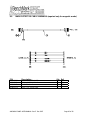
OPERATIONS AND MAINTENANCE MANUAL
WINCH OPERATORS PANEL
AMS4A141
TABLE OF CONTENTS
SECTION
DESCRIPTION
1.0
GENERAL DESCRIPTION
2.0
DETAILED DESCRIPTION OF FEATURES
3.0
MENU OPERATING INSTRUCTIONS
OPEN HOLE MODE
4.0
SYSTEM OPERATING INSTRUCTIONS
5.0
SPARE PARTS LIST
6.0
DRAWINGS AND SETUP PROCEDURES
7.0
INSTALLING NEW SOFTWARE
8.0
CABLE DRAWINGS
AMS4A141 PANEL USER MANUAL Rev E Dec 2007
Page 1 of 42
1.0
INTRODUCTION
1.1
GENERAL DESCRIPTION
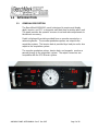
The BenchMark AMS4A141 panel is designed to acquire and display
depth, tension, and CCL or magnetic mark data from a wireline winch unit.
The panel provides the operator a means to set and make adjustments to
the data as necessary.
Depth is displayed from data provided from an encoder mounted on a
measuring device. The encoder quadrature pulses are output to the
acquisition system. The tension data is provided by a load pin and is also
output to the acquisition system.
The encoder quadrature pulses, tension data, and magnetic marks are
passed through to the acquisition system. The output connectors are
compatible with the SDS Warrior system.
AMS4A141 PANEL USER MANUAL Rev E Dec 2007
Page 2 of 42
1.2
FEATURES AND SPECIFICATIONS
--
Digital displays for depth, line speed, tension and magnetic marks, CCL depth
offset, or last detected collar depth.
--
Analog incremental tension meter, 4 inch (108 mm) dia., 270 degree
--
Differential or Incremental tension zero push button switch
--
Excessive tension alarm setting allows operator to set tension alarm to a
predetermined value. Contact closure is provided for winch shutdown
--
Zero Depth button - sets depth to 0. Depressing button again resets depth to
previous setting. Only works when line speed is zero
--
Approaching surface alarm
--
Depth adjust up or down switches. Only works when winch is stopped
--
Load cell zero & calibrate controls. Only works when there is no load on cable
--
Depth & tension saved in non-volatile memory at power loss
--
Outputs for Magnetic Marks, Tension and Encoder to interface to an acquisition
system. Outputs are compatible with SDS Warrior.
--
RS232 Interface for additional control and data outputs.
--
Can be set to display either English or Metric units or a combination of English
and Metric units (i.e. depth in feet, tension in KG).
--
Panel is powered by 12-24vdc. All sensor power (encoder, load pin, MMD,
etc) is provided by the panel. No other power supplies are needed.
AMS4A141 PANEL USER MANUAL Rev E Dec 2007
Page 3 of 42
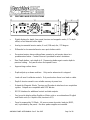
2.0 DETAILED DESCRIPTION OF FEATURES
2.1
FRONT PANEL
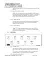
2.1.1 ANALOG TENSION METER
This meter displays either differential or incremental tension. This
provides a more visual display of tension change.
2.1.2 INCREMENTAL/TOTAL TENSION SWITCH
This switch will change the analog meter from Incremental tension to
Differential tension.
Incremental tension provides a high resolution tension scale. It must
be periodically reset as tension increases or decreases to keep it
from pegging out.
Differential tension provides a delta tension reading. The meter will
slowly reset itself to 0 so the reset switch is not necessary.
2.1.3 METER RESET SWITCH
This switch will reset the meter to the 0 (center) position.
2.1.4 DEPTH DISPLAY
This meter provides a digital display of depth.
2.1.5 LINE TENSION DISPLAY
This meter provides a digital display of total line tension.
AMS4A141 PANEL USER MANUAL Rev E Dec 2007
Page 4 of 42
2.1.6 LINE SPEED DISPLAY
This meter provides a digital display of line speed.
2.1.7 MAGNETIC MARK / CCL DISPLAY
This meter provides a digital display of the depth where the last
mark was detected. It can also used as a CCL offset display or the
depth of the last Collar detected.
2.1.8 MAGNETIC MARK RESET
Pressing the MMD reset button clears the last mark setting. The
next mark detected will be used to set the window for any
subsequent marks.
2.1.9 ZERO DEPTH
Pressing this button will reset the depth to 0. Depressing the button
again will reset the depth to the previous setting. The Zero Depth
button will only work when the line speed is zero (i.e. winch not
moving).
2.1.10 MENU
Pressing this button will activate the menu software. The software
feature to be set will be displayed on the DEPTH display. The
features can be toggled through by pressing the menu button until
the desired feature is displayed.
2.1.11 + / - SWITCH
This switch is used for different functions. It is used to change the
depth setting in either an up or down direction. The winch must be
stopped before the depth can be set. In menu mode (see section
3.0) the switch is used to set menu parameters.
2.1.12 APPROACHING SURFACE LED AND ALARM
This LED is lit and an audible alarm is sounded when the depth is
less than 100' (30 m). This is a warning to the hoist operator that
they are approaching surface and should take care to get the
equipment safely out of the well. When the LED is depressed, the
alarm will stop but the LED will continue to blink. Once the depth
AMS4A141 PANEL USER MANUAL Rev E Dec 2007
Page 5 of 42
reading is greater than 100' (30 m), both the alarm and the LED will
turn off.
2.1.13 ENGLISH / METRIC UNITS
These LEDs will indicate if the panel is in English or metric mode. If
the depth is set to English, the English LED will be lit. If the depth is
set to Metric the Metric LED will be lit. The tension can be set to
English (LBS) or Metric (KG) but it will not light the LED.
2.1.14 T-ZERO SWITCH
Use this switch to set the tension to 0 at the start of a logging run.
This will zero out the tension circuit. The line should be slack
through the head at this time.
2.1.15 T-TEST SWITCH
Press T-TEST and verify that the panel tension reads 20000 lbs
(MODE 5) or 5000 lbs (MODE 3). Verify tension is being properly
recorded on acquisition system.
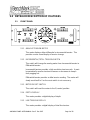
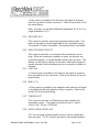
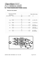
2.2
REAR PANEL
2.2.1 POWER INPUT
This connector supplies dc power for the panel operation (9 VDC
min, 30 VDC max). The panel can operate on either 12 or 24 vdc
(12 vdc is U.S. truck standard voltage, 24vdc is European truck
standard voltage). Pin A is positive, pin B is negative.
2.2.2 ENCODER 1, ENCODER 2,
AMS4A141 PANEL USER MANUAL Rev E Dec 2007
Page 6 of 42
+5 vdc power is provided to the encoders and signal is received
from the encoders on these connectors. Refer to the section 6.0 for
the pinout listing..
Note: encoders can be either differential quadrature (A, B, A/, B/ or
single quadrature (A, B).
2.2.3 ENCODER OUT
This connector provides an encoder quadrature data output. This
data can be used to provide depth data to the acquisition system.
The output PPF data is selectable. No encoder power is provided.
2.2.4 OVER TENSION CONTACT
This connector provides a connection to the overtension circuit
relay. When an overtension condition is active, the two pins are
connected together. In normal position the two pins are open. This
feature can be used to interface to the winch unit control system to
provide automatic hoist shutdown when an overtension condition is
reached.
2.2.5 LOAD PIN
+/- 15vdc power is provided to the load pin and signal is received
from the load pin on this connector. Refer to the section 6.0 for the
pinout listing..
2.2.6 MMD / CCL
+ 15vdc power is provided to the magnetic mark detector and signal
is received from the mark detector on this connector. Refer to the
section 6.0 for the pinout listing..
2.2.7 TENSION OUT
This connector provides a 4-20ma tension data output to the
acquisition system. The output is provided on pins C and D.
4 ma = 0 lbs, 20 ma = 12,500 lbs
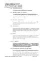
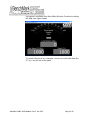
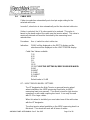
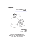
2.2.8 RS232 SERIAL INTERFACE
A PC can be used to display depth, tension, and line speed data
from the panel. The PC can also be used to set panel parameters.
AMS4A141 PANEL USER MANUAL Rev E Dec 2007
Page 7 of 42
A program is available from BenchMark Wireline Products to display
this data (see figure below).
To connect the panel to a computer, connect a serial cable from the
PC to J6 on the rear of the panel.
AMS4A141 PANEL USER MANUAL Rev E Dec 2007
Page 8 of 42
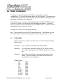
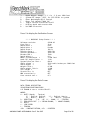
3.0 MENU COMMANDS
This panel has internal software which allows it to be set for various
configurations. To change the settings, press the MENU button. The feature to be
set will be displayed on the DEPTH display. Press the MENU button again until
the feature you want to set is displayed.
The parameters for each feature will be displayed on the LINE TENSION display.
Press the +/- switch to cycle through all the available parameters. When the
value you want to select is displayed, press the MENU button. ACCEPT will then
be displayed. Press + for yes, - for no.
Following is a listing of all the available settings.
Note: These options are for the AM3K measuring head. The software can also
be configured for an AM5K measuring head by removing the jumper on JP3.
3.1
TEN ALARM
When preset tension value is reached, alarm sounds and tension display
flashes value
Procedure:
Use +/- switch to set the tension alarm setting.
Indication:
TALARM will be displayed on the DEPTH display and the
value will be displayed on the TENSION display as it is being
set.
Selection:
Each cable size will have a corresponding Tension Alarm
setting. Only the setting for the cable size selected (see
menu option 1) can be adjusted.
Default Values
7-32
9-32
5-16
3-8
7-16
15-32
15-32HT
SLAM
SLAMHT
S-SLAM
1500
2400
2400
2400
2400
2400
2400
2400
2400
2400
AMS4A141 PANEL USER MANUAL Rev E Dec 2007
Page 9 of 42
3.2
S-SLAMHT 2400
DELTA TENSION ALARM
When the delta tension setting is reached the alarm sounds. In incremental
mode, you must periodically press meter reset or this alarm will sound when
the tension reaches the set value. In differential mode, the meter will reset
itself and the alarm will only sound on a quick change of tension. The Alarm
Reset switch must be pressed to reset the over tension relay.
3.3
Procedure:
Use +/- switch to set the Delta Tension setting.
Indication:
DTALRM will be displayed on the DEPTH display and the
value being set will be displayed on the TENSION display as
it is being adjusted.
TENSION SHUTDOWN
When value is reached, alarm sounds, tension display flashes value, and
tension contact closure switch is closed. This can be used to provide a
signal to automatically stop the winch.
Procedure:
Use +/- switch to set tension shutdown setting
Indication:
OVRTEN will be displayed on the DEPTH display and the
value will be displayed on the TENSION display as it is being
set.
Selection:
Each cable size will have a corresponding Tension Alarm
setting. Only the setting for the cable size selected can be
adjusted.
Default Values
7-32
9-32
5-16
3-8
7-16
15-32
15-32HT
SLAM
SLAMHT
S-SLAM
S-SLAMHT
2000
3000
3500
3500
3500
3500
3500
3500
3500
3500
3500
AMS4A141 PANEL USER MANUAL Rev E Dec 2007
Page 10 of 42
3.4
CABLE SIZE
Cable size selection automatically sets load pin angle setting for the
selected cable size.
In mode 3, wheel size is also automatically set for the selected cable size.
If other is selected, the LCA value needs to be entered. This value is
based on the bend angle of the cable over the tension wheel. This value is
empirically derived and must be furnished by the measuring head
manufacturer.
Procedure:
Use +/- switch to select cable size.
Indication:
CABLE will be displayed on the DEPTH display and the
selections will be displayed on the LINE TENSION display.
Cable Size Values available
7-32
9-32
5-16
3-8
7-16
15-32
15-32HT USE THIS SETTING W/ DEEP GROOVED WHEEL
SLAM
SLAMHT
S-SLAM
S-SLAMHT
OTHER
Default value is SLAM
HT – HIGH TENSION WHEEL SETTINGS
The HT designates the High Tension or grooved tension wheel
when installed on the AM5K measuring head (refer to AM5K
measuring head user manual). This wheel is used for high tension
operations or with cable requiring less bend. It can only be used
with 15-32 or large cables.
When this wheel is installed, you must select one of the cable sizes
with the HT designator.
The other tension wheel available on the AM5K measuring head is a
flat wheel. This wheel will work will all sizes of cables.
AMS4A141 PANEL USER MANUAL Rev E Dec 2007
Page 11 of 42
OTHER
If you select the "OTHER" setting, you will be allowed to change the
measuring wheel circumference and the load cell factor. This allows
the panel to with a different type of measuring head or a different
load cell, such as a derrick mounted load cell.
When "OTHER" is selected, two additional inputs will be required:
LCFACTOR and WHLCIR.
LCFACT (Load Cell Factor). This setting determines the ratio
between the input signal and the tension value displayed. A
setting of 2 will decrease the tension value by ½. A setting of
.5 will double the tension reading.
Default value is 1.
WHLCIR (Wheel Circumference). This value is set to the
circumference of the measuring wheel to ensure the depth is
measured correctly. Default value is 2.0 ft.
3.5
DEPTH ADJUST (Shim)
The shim amount selected will automatically be added or subtracted from
the depth input.
3.6
Procedure:
Use +/- switch to set the shim setting.
Indication:
DP-ADJ will be displayed on the DEPTH display and the
value will be displayed on the TENSION display as it is being
set. The values are feet / thousand.
Default value is 0.
DEPTH ALARM
When Alarm depth value is reached, the alarm will sound and LED will
flash. Pressing the LED will turn off alarm but the light will continue to
flash.
Procedure:
Use +/- switch to set the depth alarm value.
Indication:
DALARM will be displayed on the DEPTH display and the
value will be displayed on the TENSION display as it is being
set. Default value is 100’
AMS4A141 PANEL USER MANUAL Rev E Dec 2007
Page 12 of 42
3.7
MMD or CCL
Either MMD or CCL can be selected. MMD provides a the ability to detect
magnetic marks. CCL provides a means to display the offset between the
CCL depth and the bull plug depth.
Procedure:
Use +/- switch to select either MMD or CCL.
3.7.1 CCL
The CCL depth will be displayed on the MMD meter. This makes it
easier to monitor CCL depth in addition to bottom of tool depth. The
following menu options are available.
CCL OFFSET
The CCL depth will be displayed on the MMD meter. This
makes it easier to monitor CCL depth in addition to bottom of
tool depth.
Procedure:
Use +/- switch to set the CCL offset depth
Indication: CCL will be displayed on the DEPTH display and the
value will be displayed on the TENSION display as it is being set.
OFFSET
Use +/- switch to set the CCL offset depth
LOG
The following menu options are available:
LOG CCL
Displays latest 100 collars. Will overwrite the oldest collar
after 100.
CCL DLY
Use +/- switch to set delay from 1.0 to -0.1 Adds or subtracts
to detected collar depth.
CCL_BP
Turns detected CCL audio on or off.
STRCOR (stretch correction)
Use +/- switch to toggle between ON or OFF
AMS4A141 PANEL USER MANUAL Rev E Dec 2007
Page 13 of 42
When STRETCH Correction is on, the panel will automatically
correct depth to compensate for cable stretch. The following
information will then be requested:
TOOLWT
The weight of the tool string at the end of the cable. Default
value is 1000 lbs.
FLUIDW
The fluid weight of the well bore fluids. Default value is 8.3
lbs.
Stretch in the wireline is compensated in the following
manner:
As the tool is lowered into the well the depth traveled is measured
using the optical encoders 10 times a second. The tension is used
to “back out” the stretch on the wireline for that segment and a non
stretched depth is calculated by keeping a tally of all of the
segments. This summed value is used in the following manner to
calculate the depth:
If the tension is less than the calculated line weight the tool is
assumed to be floating or supported in some other manner. The
tension is due to the line weight so the stretch added is = summed
depth * tension * Ks * 1/2 where Ks is the stretch coefficient. If the
tension is greater than the line weight the stretch due to the line
weight is calculated as above and all other weight is assumed to be
acting over the entire length of the cable or = sum depth *((line
weight * ½) + (tension-line weight)) * Ks
CCL LOG
Press the +/- switch and you will be able to see the depth at
which each casing collar was detected. The MMD/CCL
display will display the depth of each collar when the switch is
pressed.
3.7.2 MMD
The following menu options are available.
MMDCOR (MMD Correction)
Use +/- switch to toggle between ON or OFF
AMS4A141 PANEL USER MANUAL Rev E Dec 2007
Page 14 of 42
If MMD is set to ON the panel will automatically correct depth
to correspond to magnetic mark spacing. When depth is
automatically added or subtracted it will be done evenly at a
rate of 1’ per 10’.
STR CORR (Stretch Correction)
Stretch Correction works differently depending if MMD
correction is ON or OFF.
If MMD Correction is ON and STRCORR is ON, the panel will
automatically correct the MMD WINDOW depth to
compensate for cable stretch. The Mark Window will change
as the cable stretches to make sure the window is always set
properly.
STRCORR can be turned off by selecting OFF. No stretch
will be added in this case.
If MMD Correction is OFF or STRCORR is off, no stretch will
be calculated.
If STRCORR is turned ON, the following information will be
requested:
TOOLWT
The weight of the tool string at the end of the cable.
Default value is 1000 lbs.
FLUIDW
The fluid weight of the well bore fluids.
Default value is 8.3 lbs.
SPACNG
This is to set the spacing at which the magnetic marks were
installed on the wireline.
Use +/- switch to toggle between 100, 25 M, 50 M.
WINDOW
The MMD window determines when the next mark can be
detected. The cable must travel at least the distance of the
AMS4A141 PANEL USER MANUAL Rev E Dec 2007
Page 15 of 42
mark spacing (100’, 50m or 25m) – the window setting,
before a mark can be detected. Marks can only be detected
if they occur within this window. If the window is set for 5'
and the mark spacing is 100’, the cable must travel no less
than 95' and no more than 105’ from the last mark before a
new mark can be detected.
The MMD Depth display will blink when the depth is within the
mark Window.
The Window is disabled after the MMD Reset button is
pressed and will not be enabled until the first mark is
detected.
Procedure:
Use +/- switch to change MMD window value.
Indication:
MMD will be displayed on the DEPTH display
and the window value will be displayed on the
TENSION display as it is being set.
Pressing the MMD reset button clears the last
mark setting.
MMD LOG
The depth of the first 25 detected marks is stored in memory
and can be displayed.
Procedure:
Use +/- switch to toggle through all of the marks
that have been detected. This starts from the
last mark detected. Pressing depth 0 will clear
all the stored marks.
Indication:
MMD DP will be displayed on the DEPTH
display and the mark depth will be displayed on
the TENSION display.
AMS4A141 PANEL USER MANUAL Rev E Dec 2007
Page 16 of 42
3.8
ENCODER SELECT
This function allows the user to change encoders by selecting
a different encoder connected to the panel.
Procedure:
Use +/- switch to select which encoder input on the rear panel
will be used.
Indication:
ENCSEL will be displayed on the DEPTH display and the
encoder selected appears on the Depth display.
a. ENC 1
b. ENC 2
c. BOTH
If BOTH is selected, the depth will be a composite of ENC 1
or 2. The two encoders are compared 10 times per second
and the encoder that moves the furthest at each comparison
will be used to increment the composite depth.
Note: Encoder 1 will always turn the opposite direction from encoder 2. In
direct mode (see section 3.11), the encoder output will be in the same
direction as encoder 1.
3.9
ENCODER PULSES PER REVOLUTION
The value selected will automatically be used as the encoder input pulses
per revolution (PPR) setting.
3.10
Procedure:
Use +/- switch to set the ENCODER Pulse Per Revolution
setting.
Indication:
ENCDOR will be displayed on the DEPTH display and the
value will be displayed on the TENSION display as it is being
set. Default value is 1200.
ENCODER DIRECTION
The value selected will toggle the encoder direction between UP and
Down.
Procedure:
Use +/- switch to set the ENCODER direction setting.
Indication:
ENCDIR will be displayed on the DEPTH display and either
UP or DN value will be displayed on the TENSION display.
Default value is UP.
AMS4A141 PANEL USER MANUAL Rev E Dec 2007
Page 17 of 42
3.11
ENCODER OUT – SYSTEM PULSES PER FOOT
This setting determines the encoder pulse rate that will be output to the
acquisition system.
3.12
Procedure:
Use +/- switch to set the encoder output value.
Indication:
SYSPPF will be displayed on the DEPTH display and the
value will be displayed on the TENSION display as it is being
set.
DEPTH UNITS
The depth values will be displayed in the units selected.
3.13
Procedure:
Use +/- switch to set the DEPTH UNITS setting.
Indication:
DEPTH will be displayed on the DEPTH display. The
selection can be toggled between FEET or METERS. The
selection will be displayed on the TENSION display. The
ENGLISH (green) LED display will be lit when FEET is
selected and the METRIC (red) LED will be lit when
METERS is selected.
TENSION UNITS
The tension value will be displayed in the units selected.
Procedure:
Use +/- switch to set the TENSION UNITS setting.
Indication:
TENSION will be displayed on the DEPTH display. The
selection can be toggled between POUNDS and KILOGM.
The selection will be displayed on the TENSION display.
AMS4A141 PANEL USER MANUAL Rev E Dec 2007
Page 18 of 42
4.0 SYSTEM OPERATING INSTRUCTIONS
4.1
Power up panel and verify it is working properly.
4.2
Verify the panel is configured to match the system (head type, system
output, encoder, etc.)
4.3
Set up acquisition system:
4.4
Press T-Zero and verify that panel tension reads 0. Verify tension is
recorded on acquisition system.
4.5
Set line size to match cable size installed in head (refer to section 3).
4.6
Set Tension Alarm value (refer to section 3).
4.7
Set depth adjust value (refer to section 3).
4.8
Install cable in measuring head and lay it slack on the ground.
4.9
Press T-Zero to zero the tension value.
4.10
Press T-Test and verify that panel tension reads 10000 lbs. Verify tension
is being properly recorded on acquisition system.
4.11
Pull tool to depth 0 position. Press D-Zero and verify that panel depth
reads 0. Set acquisition system depth to 0 at this time.
AMS4A141 PANEL USER MANUAL Rev E Dec 2007
Page 19 of 42
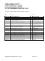
5.0 RECOMMENDED SPARE PARTS LIST
AMS4A141 PANEL WINCH OPERATOR DISPLAY PANEL
P/N
Description
Qty Reference
AMS4P134E
AMS4P110
AMS4P128
ACMU1P06
ACMU1P11
AMS4P020
AMS4P018
PC BOARD AMS40 REV E
METER ANALOG DIFF TENSION (+/- 1000 LBS)
DISPLAY LED .5" SERIAL 2"X3.5"
LED RED DIALIGHT 5V
SONALERT #SC628D MALLORY
SWITCH MTL-106D ALCO LOCKING
SWITCH MPA-106F ALCO PUSH MOM
1
1
4
1
1
2
5
AMS4P044
AMS4P021
SWITCH TOGGLE DPDT MOM OFF MOM
SWITCH CAPS ALCO C-22 BLACK
1
3
AMS7P017
ACMU3P01
ACMU3P02
SWITCH CAP ALCO C-22 RED
CONN MS3102E-14S-9P RECEPT
CONN MS3102E-14S-9S RECEPT
1
1
1
MOTHER BOARD
M1
D1 – D4
APPROACHING SURF
ALARM
POWER ON/OFF
MENU,T-ZERO,T-TEST,DZERO,METER RESET
+/T-ZERO,D-ZERO,METER
RESET
D-ZERO, MENU
POWER IN
OVER TENSION OUT
AMS4P037
AMS7P013
AMS4P170
AMS4P038
AMS4P041
AMS4P042
AMS4P043
CONN MS3102E-16S-1P 7 PIN RCP
CONN MS3102E-18-9P LOAD CELL
CONN KPSE02E12-10P RECEPTACLE
CONN MS3102E-16S-1S 7 SOC RCP
SWITCH PUSHBUTTON LIGHTED SPST
LENS RED C&K SWITCH
LED RED FOR C&K PUSHBUTTON SW
1
1
1
2
1
1
1
ENCODER OUT
LOAD PIN IN
J5 - MMD
ENCODER1,2 IN
APPROACHING SURF
RED LENS
RED LED
AMS4A141 PANEL USER MANUAL Rev E Dec 2007
Page 20 of 42
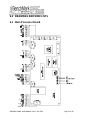
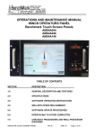
6.0 DRAWINGS AND WIRE LISTS
6.1 Main Processor Board
AMS4A141 PANEL USER MANUAL Rev E Dec 2007
Page 21 of 42
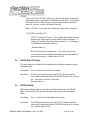
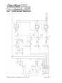
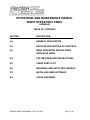
6.1.1
ENCODER AND MMD INPUTS
AMS4A141 PANEL USER MANUAL Rev E Dec 2007
Page 22 of 42
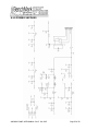
6.1.2
ENCODER OUTPUT AND COM PORT I/O
AMS4A141 PANEL USER MANUAL Rev E Dec 2007
Page 23 of 42
6.1.3
LOAD PIN AND TENSION I/O
AMS4A141 PANEL USER MANUAL Rev E Dec 2007
Page 24 of 42
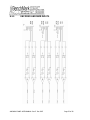
6.1.4 JUMPERS – BUTTONS
AMS4A141 PANEL USER MANUAL Rev E Dec 2007
Page 25 of 42
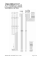
6.1.5 POWER SUPPLIES
AMS4A141 PANEL USER MANUAL Rev E Dec 2007
Page 26 of 42
6.2 BACK PANEL CONNECTOR PINOUT
POWER IN A
POWER IN B
12 - 24 VDC IN
12 - 24 VDC GROUND
ENC
ENC
ENC
ENC
ENC
ENC
1
1
1
1
1
1
A
B
C
D
E
F
ENCODER
ENCODER
ENCODER
ENCODER
ENCODER
ENCODER
QUADRATURE
QUADRATURE
QUADRATURE
POWER - +5
QUADRATURE
IN GROUND
IN PHASE
IN PHASE
IN PHASE
VDC
IN PHASE
A
B
B*
ENC
ENC
ENC
ENC
ENC
ENC
2
2
2
2
2
2
A
B
C
D
E
F
ENCODER
ENCODER
ENCODER
ENCODER
ENCODER
ENCODER
QUADRATURE
QUADRATURE
QUADRATURE
POWER - +5
QUADRATURE
IN GROUND
IN PHASE
IN PHASE
IN PHASE
VDC
IN PHASE
A
B
B*
ENC
ENC
ENC
ENC
ENC
OUT
OUT
OUT
OUT
OUT
ENCODER
ENCODER
ENCODER
ENCODER
ENCODER
QUADRATURE
QUADRATURE
QUADRATURE
QUADRATURE
OUT GROUND
OUT
OUT
OUT
OUT
A
B
C
E
F
-
A*
A*
PHASE
PHASE
PHASE
PHASE
O-TEN A
TENSION CONTACT RELAY COMMON
O-TEN B
TENSION CONTACT RELAY N.O.
LOAD
LOAD
LOAD
LOAD
LOAD
LOAD
PIN
PIN
PIN
PIN
PIN
PIN
B
C
D
E
F
G
A
B
B*
A*
+15 VDC LOAD PIN POWER
-15 VDC LOAD PIN POWER
GROUND
LOAD PIN SIGNAL+
LOAD PIN SIGNALSHUNT CAL
AMS4A141 PANEL USER MANUAL Rev E Dec 2007
Page 27 of 42
MMD/CCL
MMD/CCL
MMD/CCL
MMD/CCL
MMD/CCL
MMD/CCL
-
C
D
E
F
G
B
MARK+
MARKMMD POWER +
COMMON
CCL +
CCL -
RS232 2
RS232 3
RS232 5
SERIAL PORT TRANSMIT
SERIAL PORT RECEIVE
SERIAL PORT GND
TEN OUT B
0 – 10V TENSION OUTPUT SIGNAL
TEN OUT C
TEN OUT D
TENSION OUTPUT SIGNAL GROUND
4 – 20 MA TENSION OUTPUT SIGNAL
AMS4A141 PANEL USER MANUAL Rev E Dec 2007
Page 28 of 42
6.3 FUSE BOARD AND POWER WIRING
Refer to 5.2 for wirelist
AMS4A141 PANEL USER MANUAL Rev E Dec 2007
Page 29 of 42
6.4
DIGITAL DISPLAY SETUP
The four digital displays can be set for address, baud rate, and brightness.
The button nearest the connector selects the parameter (address, baud rate,
brightness).
The center button increments the parameter up
The end button increments the parameter down.
After the parameter is set, press the parameter button again to store it.
The addresses should be set as follows:
Line Tension = 1
Line Speed = 2
Depth = 3
MMD = 4
Set Baud Rate to 9600
Set Brightness to 15
6.5 RS232 SERIAL INTERFACE
The wiring is as follows:
DB9 PIN OUT: 2 = TRANSMIT, 3 = RECEIVE, 5 = GROUND
Run a program such as MS Windows HyperTerm using the following
parameters
BAUD
BITS
PARITY
STOP
38,400
8
N
1
Press H or ? to display the help screen
* * * AMS4A141 Help Screen * * *
H,?
D
L
P
V
W
Z
U
A
N
M
-
-
This screen.
Display units, direction, depth, speed, and tension.
Modify load cell angle (factor) Usage: L1.2
Modify encoder pulses/revolution. Usage: P600
Verify WDDU setup status.
Modify wheel size (line other) (feet) Usage: W4.0
Preset depth.Usage: Z0.0 |_|--> New depth.
Modify units of measure UE or UM
Depth Alarm. Usage: A100 |_|--> Depth Alarm.
Line Size N0 7/32; N1 9/32; N2 5/16; N3 3/8;N4 7/16;
N5 15/32; N6 15/32HT; N7 SLAM N8 SLAMHT; N9 SSLAM
Tension Alarm. Usage: 'M2500' for 2500 pound alarm.
AMS4A141 PANEL USER MANUAL Rev E Dec 2007
Page 30 of 42
J
S
B
T
k
p
m
-
Depth Adjust. Usage: 'J-1' for -1 ft per 1000 feet
System PPF Usage: 'S125' for 125 PPFoot to system
Enter Mud Weight B12.3 lbs/gal
Enter Tool Weight T1000 lbs
Toggle stretch correction on/off
Display depth and stretch data
Use MMK Correction
Press V to display the Verification Screen
* * * AMS4A141 Setup Status * * *
Software revision
Line Size =
Depth Units =
Depth Units =
Depth alarm =
Tension alarm =
Tension shutdown =
Encoder PPR =
Depth Adjust =
Wheel Circumference =
Load Cell Angle Factor =
System Pulse per Foot =
Cable volume =
Cable weight =
Weight fluid =
Cable weight fluid =
Tool weight =
Stretch Corr is
MMK correction is
Line stretch tool =
S4100.01
slam
Feet
Pounds
100 ft
2400 lbs
3500 lbs
1200
0.0
2.000 feet
1.00
600.0
2118 cubic inches per 1000 feet
1.0
8.300
1.000
1000
OFF
OFF
8.3
Press D to display the Data Screen
DATA STRING DESCRIPTION
12345678901234567890123456
U D Zddddd.d ssss.s tttttt<CR><LF>
WHERE:
U – UNITS (Depth,
Tension)
'E' - English, English,
'G' - English, Metric,
'M' - Metric, Metric,
'F' - Metric, English
D - DIRECTION
('U' - UP; 'D' - DOWN; 'S' - STOPPED)
Z - ZERO DEPTH REF. ('+' BELOW GROUND; '-' ABOVE GROUND)
d - DEPTH
s - LINE SPEED
t - TENSION
<CR> - CARRIAGE RETURN, <LF> - LINEFEED
AMS4A141 PANEL USER MANUAL Rev E Dec 2007
Page 31 of 42
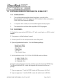
INSTALLING NEW SOFTWARE
7.1
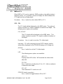
SOFTWARE MODIFICATION BY REPLACING THE EPROM
The software that controls this panel is stored in an EPROM Integrated Circuit
located at U2 (see drawing on next page). To upgrade the software to a new
version, simply remove the eprom I.C. and install a new eprom I.C. (be careful not
to bend the legs during installation).
After new software is installed, make sure and "reboot" the panel by turning off the
panel, depressing the T-ZERO and T-TEST buttons simultaneously then turn the
power back on while the buttons are depressed.
J1 = DEPTH UNITS, ON = METERS, OFF = FEET
J2 = TENSION UNITS, ON = KG, OFF = POUNDS
J3 = HEAD TYPE, ON = AM3K, OFF = AM5K
AMS4A141 PANEL USER MANUAL Rev E Dec 2007
Page 32 of 42
7.2
SOFTWARE MODIFICATION USING THE SERIAL PORT
7.2.1 PREREQUISITES:
1.
The real-time data acquisition board must have a socket for the
MicroController and a CPU piggy-back PCB installed in that socket with a
DS98C450 MicroController installed.
2.
A computer with a serial port, and installed Hyperterminal program.
3.
The new revision real-time data acquisition HEX file program.
7.2.2 PROCEDURE:
1. Transfer the new revision HEX file to a PC with a serial port or a USB to serial
adapter.
2. Turn power on to the Hoistman’s panel.
3. Connect your PC to the serial port at the rear of the panel.
4. Open a Hyperterminal session. Use the following settings:
Serial Port: COM1
Baud Rate: 57600
Data Bits: 8
Parity: None
Stop Bits: 1
Flow Control: None
5. Set the switches on the CPU PCB to PROGRAM mode as follows:
1 - AWAY FROM CPU
2 – AWAY FROM CPU
3 - TOWARD CPU
6.Open the Hyperterminal connection and then press the keyboard ENTER key.
The MicroController ROM Loader will respond with a banner and then a '>'
prompt.
7. Type an uppercase 'K' and the ROM Loader will Klean-erase the Flash.
8. Type an uppercase 'L' and the ROM Loader will wait to Load a HEX file.
AMS4A141 PANEL USER MANUAL Rev E Dec 2007
Page 33 of 42
9. Pull down the Hyperterminal TRANSFER menu and choose: Send Text File.
The file browser will open, so ensure that the file filter is set to:
Files of type - All files (*.*) and then go to the C:\ root directory and choose the
new revision HEX file to transfer.
10. The ROM Loader will begin programming the Flash and will report a GOOD
status for the duration of the programming procedure as follows:
GGGGGGGGGGGGGGGGGGGGGGGGGGGGGGGGGGGGGGGGGGGGGGGGGG
GGGGGGGGGGGGGGGGGGGGGGGGGGGGGGGGGGGGGGGGGGGGGGGGGG
GGGGGGGGGGGGGGGGGGGGGGGGGGGGGGGGGGGGGGGGGGGGGGGGGG
GGGGGGGGGGGGGGGGGGGGGGGGGGGGGGGGGGGGGGGGGGGGGGGGGG
GGGGGGGGGGGGGGGGGGGGGGGGGGGGGGGGGGGGGGGGGGGGGGGGGG
GGGGGGGGGGGGGGGGGGGGGGGGGGGGGGGGGGGGGGGGGGGGGGGGGG
GGGGGGGGGGGGGGGGGGGGGGGGGGGGGGGGGGGGGGGGGGGGGGGGGG
GGGGGGGGGGGGGGGGGGGGGGGGGGGGGGGGGGGGGGGGGGGGGGGGGG
GGGGGGGGGGGGGGGGGGGGGGGGGGGGGGGGGGGGGGGGGGGGGGGGGG
GGGGGGGGGGGGGGGGGGGGGGGGGGGGGGGGGGGGGGGGGGGGGGGGGG
GGGGGGGGGGGGGGGGGGGGGGGGGGGGGGGGGGGGGGGGGGGGGGGGGG
GGGGGGGGGGGGGGGGGGGGGGGGGGGGGGGGGGGGGGGGGGGGGGGGGG
GGGGGGGGGGGGGGGGGGGGGGGGGGGGGGGGGGGGGGGGGGGGGGGGGG
GGGGGGGGGGGGGGGGGGGGGGGGGGGGGGGGGGGGGGGGG
11. After the ROM Loader is finished programming the Flash set the switches on
the CPU piggy-back PCB as follows:
1 - TOWARD CPU
2 - TOWARD CPU
3 - AWAY FROM CPU
12. To operate from an EPROM instead of the Micro-Controllers internal memory,
set the switches on the CPU piggy-back PCB as follows:
1 - TOWARD CPU
2 – TOWARD CPU
3 - TOWARD CPU
AMS4A141 PANEL USER MANUAL Rev E Dec 2007
Page 34 of 42
8.0
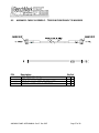
8.1
CABLE DIAGRAMS
AMS8A024 CABLE ASSEMBLY – TENSION FROM MEASURING HEAD TO
PANEL
P/N
AMS4P221
AMS8P057
AMS7P014
AMS8P059
AMS8P060
AMS1P029
Description
Qty Ref
20 FT
CABLE 20/8C ALPHA 25468 BLACK
CONN KPT06A16-8S STR PLUG, LOAD PIN END 1 EA
1 EA
CONN MS3106E-18-9S LOAD PIN, PANEL END
1 EA
CLAMP CONN MS3057-10A W/BUSH
1 EA
DUST CAP CANNON SHELL SIZE 16
1 EA
DUST CAP MS25042
AMS4A141 PANEL USER MANUAL Rev E Dec 2007
Page 35 of 42
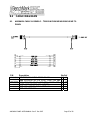
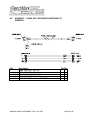
8.2
AMS4A105 CABLE ASSEMBLY - ENCODER FROM MEASURING HEAD TO
PANEL
P/N
AMS1P028
AMS4P183
AMS4P221
AMS7P040
Description
CONN MS3106F-18-1S ENCODER END
CONN MS3106F-16S-1P PANEL END
CABLE 20/8C ALPHA 25468 BLACK
DUST CAP AMPHENOL 97-60-18
AMS4A141 PANEL USER MANUAL Rev E Dec 2007
Qty Ref
1
1
20
1
EA
EA
FT
EA
Page 36 of 42
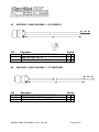
8.3
AMS4A111 CABLE ASSEMBLY – TENSION FROM PANEL TO WARRIOR
P/N
AMS4P186
AMS4P185
AMS7P061
AMS7P064
Description
CONN MS3106E-14-5
CONN MS3106E-14-5P
CABLE 16-2 SJ CORD BELDEN 8472
BUSHING #9779-513-8 AMPHENOL
AMS4A141 PANEL USER MANUAL Rev E Dec 2007
Qty Ref
1 EA
1 EA
10 FT
2 EA
Page 37 of 42
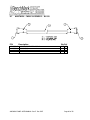
8.4
AMS4A107 – CABLE ASSY ENCODER FROM PANEL TO
WARRIOR
P/N
AMS4P184
AMS4P183
AMS7P059
AM5KP113
AMS7P064
Description
CONN MS3106E-16S-1S
CONN MS3106E-16S-1P
CABLE 20/6 BELDEN 8426
DUST CAP MS25042-16DA
BUSHING #9779-513-8 AMPHENOL
AMS4A141 PANEL USER MANUAL Rev E Dec 2007
Qty Ref
1
1
20
1
2
EA
EA
FT
EA
EA
Page 38 of 42
8.5
AMS7A022 CABLE ASSEMBLY – DC POWER IN
A=+
B=P/N
Description
AMS7P061 CABLE 16-2 SJ CORD BELDEN 8472
AMS7P044 CONN MS3106E-14S-9S
AMS7P063 BUSHING #9779-513-6 AMPHENOL
8.6
P/N
Qty Ref
5 FT
1 EA
1 EA
AMS7A023 CABLE ASSEMBLY – OT SHUTDOWN
Description
AMS7P061 CABLE 16-2 SJ CORD BELDEN 8472
AMS7P045 CONN MS3106E-14S-9P
AMS7P063 BUSHING #9779-513-6 AMPHENOL
AMS4A141 PANEL USER MANUAL Rev E Dec 2007
Qty Ref
5 FT
1 EA
1 EA
Page 39 of 42
8.7
AMS7A024 CABLE ASSEMBLY – RS232
P/N
AMS7P062
AMS7P016
AMS7P015
AMS7P067
Description
CABLE 24/2P STNDED PE/PVC
CONN DE-9P
CONN DE-9S
CONNECTOR AMP CABLE CLAMP
AMS4A141 PANEL USER MANUAL Rev E Dec 2007
Qty Ref
20 FT
1 EA
1 EA
2 EA
Page 40 of 42
8.8
CCL CABLE AMS4A137
P/N
Description
AMS4P179 CABLE COAX BELDEN 8259
AMS4P180 CONN KPSE06J12-10S STR PLUG
ALS1P030 CONN BNC PLUG
AMS4A141 PANEL USER MANUAL Rev E Dec 2007
Qty Ref
15 FT
1 EA
1 EA
Page 41 of 42
8.9
MARK DETECTOR CABLE AMS4A109 (required only for magnetic marks)
P/N
ACMU2P21
AMS4P180
AM5KP093
ACMU2P24
Description
CONN MS3106E-20-27S
CONN KPSE06J12-10S
CABLE 20/8
DUST CAP 25042-20DA
AMS4A141 PANEL USER MANUAL Rev E Dec 2007
Qty Ref
1
1
20
1
EA
EA
FT
EA
Page 42 of 42