1
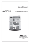
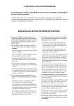
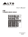
User's Manual
S-8
8-CHANNEL MIXING CONSOLE
STEREO AUX RETURN
MIC 2
MIC 1
MIC 3
MIC 4
LEFT(MONO)
2-TRACK IN/OUT
AUX SEND
RIGHT
L
2
1
2
3
1
2
3
1
2
3
LTO
S-8
8-CHANNEL MIXING CONSOLE
1
3
R
TAPE IN
LINE IN 5/6
LINE IN 1
LINE IN 2
LINE IN 3
LINE IN 4
TRIM
TRIM
TRIM
TRIM
2
TAPE OUT
LINE IN 7/8
1
3
TRIM
EQ
EQ
EQ
EQ
EQ
EQ
2
1
AUX
RETURN
1
AUX
2
1
AUX
2
1
AUX
2
PAN
1
AUX
2
PAN
1
AUX
2
PAN
1
AUX
2
PAN
BAL
BAL
4
LEVEL
1
LEVEL
2
LEVEL
3
LEVEL
4
LEVEL
5/6
LEVEL
MAIN MIX
LEVEL
7/8
www.altoproaudio.com
Version 1.2.Aug.2008
English
IMPORTANT SAFETY INSTRUCTION
CAUTION
RISK OF ELECTRIC SHOCK
DO NOT OPEN
TO REDUCE THE RISK OF ELECTRIC SHOCK
PLEASE DO NOT REMOVE THE COVER OR
THE BACK PANEL OF THIS EQUIPMENT.
THERE ARE NO PARTS NEEDED BY USER
INSIDE THE EQUIPMENT. FOR SERVICE,
PLEASE CONTACT QUALIFIED SERVICE
CENTERS.
WARNING
To reduce the risk of electric shock
and fire, do not expose this equipment
to moisture or rain.
Dispose of this product should
not be placed in municipal waste
and should be separate collection.
11. Move this Equipment only with a cart,
stand, tripod, or bracket,
This symbol, wherever used, alerts you to the
specified by the
presence of un-insulated and dangerous voltages
manufacturer, or
within the product enclosure. These are voltages that
sold with the
may be sufficient to constitute the risk of electric
Equipment. When
shock or death.
a cart is used, use
This symbol, wherever used, alerts you to
caution when
important operating and maintenance instructions.
moving the cart /
Please read.
equipment
Protective Ground Terminal
combination to
∼ AC mains (Alternating Current)
avoid possible
Hazardous Live Terminal
injury from tip-over.
ON: Denotes the product is turned on.
12. Permanent hearing loss may be caused by
OFF: Denotes the product is turned off.
exposure to \ extremely high noise levels.
CAUTION
The US. Government's Occupational Safety
Describes precautions that should be observed to
and Health Administration (OSHA) has
prevent damage to the product.
specified the permissible exposure to noise
1. Read this Manual carefully before operation.
level.
2. Keep this Manual in a safe place.
These are shown in the following chart:
3. Be aware of all warnings reported
with this symbol.
HOURS X DAY SPL EXAMPLE
4. Keep this Equipment away from water and
90 Small gig
8
moisture.
92 train
6
5. Clean it only with dry cloth. Do not use
95 Subway train
4
solvent or other chemicals.
97 High level desktop monitors
3
6. Do not damp or cover any cooling opening.
100 Classic music concert
2
Install the equipment only in accordance with
102
the Manufacturer's instructions.
1,5
105
1
7. Power Cords are designed for your safety. Do
110
0,5
not remove Ground connections! If the plug
does not fit your AC outlet, seek advice from
0,25 or less 115 Rock concert
a qualified electrician. Protect the power
According to OSHA, an exposure to high SPL in
cord and plug from any physical stress to
excess of these limits may result in the loss of
avoid risk of electric shock. Do not place
heat. To avoid the potential damage of heat, it is
heavy objects on the power cord. This could
cause electric shock or fire.
recommended that Personnel exposed to
equipment capable of generating high SPL use
8. Unplug this equipment when unused for long
hearing protection while such equipment is
periods of time or during a storm.
under operation.
9. Refer all service to qualified service personnel
The apparatus shall be connected to a mains
only. Do not perform any servicing other than
those instructions contained within the
socket outlet with a protective earthing
User's Manual.
connection.
10. To prevent fire and damage to the product,
use only the recommended fuse type as
indicated in this manual. Do not short-circuit
the fuse holder. Before replacing the fuse,
make sure that the product is OFF and
disconnected from the AC outlet.
The mains plug or an appliance coupler is used
as the disconnect device, the disconnect device
shall remain readily operable.
IN THIS MANUAL:
1. INTRODUCTION.......................................................................1
2. FEATURES..............................................................................2
3. READY TO START?....................................................................2
4. CONTROL ELEMENTS.................................................................3
5. INSTALLATION AND CONNECTION..........................................12
6. FOR THE EXPERTS WHO WANT TO KNOW MORE......................14
7.BLOCK DIAGRAM..................................................................15
8.TECHNICAL SPECIFICATION....................................................16
9.WARRANTY...........................................................................17
1. INTRODUCTION
Thank you for choosing the ▲LTO S-8 8-Channel Mixing Console, which is the
result of our ▲LTO AUDIO TEAM's endeavours. For the ▲LTO AUDIO TEAM,
music and audio is more than a profession, it is a passion and an obsession!
We have, in fact, been designing professional audio products for a number of
years in cooperation with many of the world's major brands.
The ▲LTO line represents unparalleled analogue and digital products made by
musicians, for musicians. With our design centres in Italy, the Netherlands,
and the United Kingdom we provide you with world-class designs, while our
software development teams continue to develop an impressive range of audio
specific algorithms. By purchasing our ▲LTO products you become the most
important member of our ▲LTO AUDIO TEAM. We would like to share with you
our passion for what we design and invite you to make suggestions, which will
aid us in developing future products for you. We guarantee you our commitment
for quality, continual research and development, and of course the best prices.
The ▲LTO S-8 is an extremely flexible, ultra-low noise 8-channel console,
configured with 4 mono and 2 stereo input channels, each channel is equipped
with a variety of key features including a warm, natural sounding EQ, Peak LEDs
and PAN/BAL control etc..We would like to thank all the people who made the
▲LTO S-8 8-Channel Mixing Console possible, especially to our designers and
▲LTO staff. It is their passion for music and professional audio that has made
it possible for us to offer you, our most important team member, our continued
support.
1
2. FEATURES
▲ 5 Input for Microphone and line provided with balanced 1/4" jack and XLR.
Channel 5 features stereo Line input
▲1 additional input for Line level signal provided with balanced TRS 1/4" jacks
▲ The Microphone preamplifiers are Ultra Low Noise and are provided with
+48 Volt Phantom Power
▲ Precise 3 bands graphic equalizer (LOW, MID and HI) on each input channel
▲ Pre-fader and post-fader Auxiliary bus
▲ Single Led indicating signal Peaks on each input channel
▲ Low-cut filter on all mono MIC channels
▲ 2-track input featuring RCA sockets assignable alternatively to each output
group
▲12 Segments Led Meter for optimum reading of the output signal
▲Main Output and Control Room outputs are unbalanced type
SP
OT
LI
GH
T
3. READY TO START?
3.1 Please check the AC Voltage available in your Country before connecting
your S-8 to the AC socket.
3.2 Be sure that the main power switch is turned off before connecting the
Mixer to the AC socket. Also, you should make sure that all Input and
Output Controls are turned down. This will avoid damages to your speakers
and avoid excessive noise.
3.3 Before turning on the S-8 you shall connect it to a power amplifier and
urn-on the mixer BEFORE the power ampifier. Once you have finished your
working session you shall turn the mixer off AFTER the power amplifier.
3.4 Before disconnecting the S-8 always turn-off the Power switch.
3.5 Do not use solvents to clean your S-8. A dry and clean cloth will be OK.
2
4. CONTROL ELEMENTS
FRONT PANEL
STEREO AUX RETURN
MIC 2
MIC 1
MIC 3
MIC 4
LEFT(MONO)
2-TRACK IN/OUT
AUX SEND
RIGHT
L
2
1
2
3
1
2
3
1
2
3
LTO
S-8
8-CHANNEL MIXING CONSOLE
1
3
R
TAPE IN
LINE IN 5/6
LINE IN 1
LINE IN 2
LINE IN 3
LINE IN 4
TRIM
TRIM
TRIM
TRIM
2
TAPE OUT
LINE IN 7/8
1
3
TRIM
EQ
EQ
EQ
EQ
EQ
EQ
2
1
AUX
RETURN
1
AUX
2
1
AUX
2
1
AUX
2
PAN
1
AUX
2
PAN
1
AUX
2
PAN
1
AUX
2
PAN
BAL
BAL
4
LEVEL
1
LEVEL
2
LEVEL
3
LEVEL
4
LEVEL
5/6
LEVEL
MAIN MIX
LEVEL
7/8
3
4. CONTROL ELEMENTS
1 The Mono MIC/LINE Channels
These are Channel 1 through Channel 4. You
can connect balanced, low impedance microphones to the XLR socket. On the 1/4" phone
jack you can connect either a microphone or
a line level instrument. You shall never connect
an unbalanced microphone to the XLR socket
if you do not want to damage both the Microphone and the Mixer.
MIC 1
2
1
3
2 Input Level Setting
1
This Control is provided with 2 different
indication rings: One is for the Microphone
and the other for the Line levels. When you
use a microphone you shall read the outside
ring (0-60 dB), When you use a Line level
instrument you shall read the INSIDE ring
(+15~-45 dB). For optimum operation you
shall set this control in a way that the peak
LED will blink also occasionally in order to
avoid distortion on the input channel.
BAL OR
UNBAL
LINE IN 1
TRIM
2
+15dB
0dB
-45dB LINE
60dB MIC
LOW CUT
75Hz
18dB/Oct
3
3 Low-cut Filter
By pressing this button you will activate a
75 Hz low frequency filter with a slope of
18 dB per octave. You can use this function
to reduce hum and stage rumble when
using microphones.
4 48 Volt Phantom Power
POWER
It is available only to the XLR Mic sockets.
Never plug in a microphone when phantom
power is already on. Before turning phantom
power on, make sure that all faders are all
the way down. In this way you will protect
your Stage Monitors and Main Loudspeakers.
4
PHANTOM
ON
OFF
4
4. CONTROL ELEMENTS
5 STEREO INPUTS
These are Channel 5 through 8. They
are organised in stereo pair (5&6 pair
also features XLR Mic Input) and they
are provided with 1/4" TRS phone
sockets. If you connect only the left
jack, the input will operate in mono
mode.
2
LINE IN 5/6
LINE IN 7/8
LEFT(MONO)
LEFT (MONO)
RIGHT
RIGHT
1
3
MIC (MONO)
TRIM
0dB
60dB MIC
The 3 BANDS EQUALISER
5
A 3-band equaliser is provided for all
input channels with a wide range of
frequency adjustment.
6 HI
EQ
This is the Treble control. You can use it to
get rid of high frequency noises or to boost
the sound of cymbals or the high harmonics
of the human voice. The gain range goes
from -15dB to +15dB with a centre
frequency of 12 kHz.
-15
-12
7 MID
6
MID
2.5kHz
7
LOW
80Hz
8
+12
+15
1
AUX
-
8
PRE
+15
2
POST
(PRE)
-
8
This is the Midrange control. It can affect
most fundamental frequencies of all musical
instruments and human voice. An attentive
use of this control will give you and very
wide panorama of sound effects. The gain
range goes from -12dB to +12dB and the
centre frequency is 2.5 kHz.
-15
HI
12kHz
+15
+15
PAN
8 LOW
LEFT
RIGHT
PEAK
-
8
This is the Bass control. Boost male voice
or kickdrum and bass guitar. Your system
will sound much bigger than what it is. The
gain range goes from -15dB to +15dB and
the centre frequency is 80 Hz.
+15
LEVEL
5
4. CONTROL ELEMENTS
9 AUX SENDS
These two controls will send the audio signal out to
Auxiliary busses. AUX 1 is configured as PRE-FADER.
It means that the signal is sent out before reaching
the main Fader. This will be used for stage monitors.
AUX 2 is configured as POST-FADER; therefore, the
audio signal will be affected by the Main Channel Fader.
This will be used for effects and sound processors.
However, Aux 2 can also be configured as Prefader
through any internal modification. (Please see "MODIFICATIONS" later in this Manual.)
EQ
HI
12kHz
-15
+15
MID
2.5kHz
-12
+12
LOW
80Hz
-15
+15
1
AUX
11 PEAK
Inside your S-8 the audio signal is monitored in several
different stages and then sent to the PEAK Led. When
this Led blinks, it warns you that you are reaching signal
saturation and possible distortion. The PEAK Led will blink
with a level that is 6dB before actual clipping.
12 LEVEL
This Control will adjust the overall level of this channel
and set the amount of signal sent to the Main output.
6
9
+15
2
-
8
POST
(PRE)
+15
PAN
10
LEFT
RIGHT
11
PEAK
12
-
8
This is the PANORAMA control, or balance control.
You can adjust the stereo image of the signal via
this Control. Keep this control in center position and
your signal will be positioned in the middle of stage.
Turn this control fully counterclockwise and the signal
will be present only on the left speaker and vice-versa.
Of course a wide number of intermediate positions is
available.
-
8
PRE
10 PAN
+15
LEVEL
4. CONTROL ELEMENTS
13 INSERT
CHANNEL INSERT
(PRE-FADER/PRE-EQ TIP SEND/RING RETURN)
CH4
CH3
17
2
1
+15
AUX RETURN
8
-
POWER
EFX TO AUX1
CLIP
MAX
PHONES /
CONTROL
ROOM
-
2TK TO
CONTROL ROOM
20
16
PHANTOM
2TK TO MIX
L
+15
8
18
This Control sets the amount
of signal sent either to the
Main Out socket or to the
Tape Output.
15 LED METER
CH1
13
MASTER SECTION
14 MAIN MIX LEVEL
CH2
8
Insert points are provided for
the Mono Mic Channels. When
you insert a jack in the insert
socket, the signal will be taken
out after the Input Gain Control
(Trim), sent to an external
processor such a compressor
limiter, and returned into the
channel strip immediately before
the EQ section. Of course, these
jacks used must be stereo
(Tip Send/Ring Return).
R
19
10
7
This stereo 12 segments Led
Meter will indicate the level of
the overall output signal.
4
2
0
-2
15
-4
-7
-10
16 2 TRACK signal path
-20
-30
If you push down the 2TK TO
CONTROL ROOM button, the
2 TRACK IN signal will be routed
into the Control Room output
-
8
OUTPUT LEVEL
+15
MAIN MIX
LEVEL
14
7
4. CONTROL ELEMENTS
and the level will be adjusted in level by the Control Room knob. If you push
down the 2TR TO MIX button, the 2 TRACK IN signal will be routed into the
MAIN output and will be adjusted in level by the MAIN MIX LEVEL knob.
17 AUX RETURN
The Auxiliary Return 1 and 2 are in fact two additional stereo Line inputs.
AUX RETURN 1 is configured to be assigned permanently to the Main Mix.
(It operates in Mono Mode if you connect only the left jack).The EFX TO AUX1
button is used to switch the signal from AUX RETURN 2 between MAIN MIX
and AUX SEND 1. If a signal is routed to AUX RETURN 1 and no signal is
connected to AUX RETURN 2, depressing the EFX TO AUX 1 will route the
signal to AUX SEND 1, which level will be controlled by AUX RETURN 2.
Without doubt, this feature will be very useful for you.
18 PHONES/CONTROL ROOM
This Control sets the amount of signal sent to the Control Room and
headphone.
19 PHANTOM
This LED indicates when the Phantom Power is switched on.
20 POWER
This LED indicates when the Power is on in your S-8.
23
STEREO AUX RETURN
LEFT(MONO)
2-TRACK IN/OUT
AUX SEND
RIGHT
1
1
L
22
LEFT
21
RIGHT
2
2
R
TAPE IN
8
TAPE OUT
4. CONTROL ELEMENTS
21 2-TRACK IN/OUT
Input
Use the Tape input if you wish to listen to your Mix from a Taper Recorder or
DAT, You can assign the signal coming form the Taper Recorder either to a pair
of studio monitor using the Control Room assignment on the front panel or you
can also send the signal directly to the Main Mix.
Output
These 1/4" TRS sockets will route the main mix into a tape recorder.
22 STEREO AUX RETURN
Use these stereo 1/4" phone socket to return the sound of an effect unit or
sound processor to the Main Mix. Alternatively you can use them as an extra
auxiliary input.
23 AUX SEND 1 and 2
These 1/4" phone sockets are used to send out the signal from the AUX Bus to
external devices such as effects and sound processors.
PHONES
24
24 PHONES
This socket will send out the signal mix to a pair of headphones.
9
4. CONTROL ELEMENTS
REAR PANEL
25
4
POWER
PHANTOM
CAUTION
CAUTION:
ON
RISK OF ELECTRIC SHOCK
DO NOT OPEN
REPLACE WITH THE SAME TYPE FUSE AND RATING
DISCONNECT SUPPLY CORD BEFORE CHANGING FUSE WARNING: SHOCK HAZARD - DO NOT OPEN
AVIS: RISQUE DE CHOC ELECTRIQUE - NE PAS OUVRIR
OFF
MAIN MIX OUTPUT
(BAL/UNBAL)
LEFT
RIGHT
Use only with a 250V fuse
2
CONTROL
ROOM OUTPUT
1
2
3
1
LEFT
LEFT
RIGHT
RIGHT
3
AC INPUT
EUROPE
210-240V∼50Hz
Fuse:T250mAL
RATED POWER CONSUMPTION: 18W
26
USA / Canada
100-120V ∼ 60Hz
Fuse:T500mAL
UK / Aust
240V ∼ 50Hz
Fuse:T250mAL
27
28
25 POWER
This switch is used to turn the Main Power ON and OFF.
4 PHANTOM
This switch will apply +48 Volt Phantom Power only to the 5 XLR microphone
inputs. Never connect microphones when the Phantom Power is on already.
26 AC INLET WITH FUSE HOLDER
Use it to connect your S-8 to the Main AC with the supplied AC cord. Please
check the Voltage available in your Country and make sure the voltage is
identical to the values marking on the product. Replace the fuse with the
same type by the qualified personnel only
27 MAIN MIX OUTPUT
This stereo output is supplied both with XLR and 1/4" jack socket and it is
controlled by the Main Mix Level on the front panel. It will send the audio
signal to an amplifier. The output level can be varied from -∞ to +15dB.
28 CONTROL ROOM OUTPUT
These 1/4" phone sockets will be used to send the signal to Studio Monitor
speakers or to a second set of PA.
10
5. INSTALLATION AND CONNECTION
Ok, you have got to this point you are now in the position to successfully
operate your S-8. However, we advise you to read carefully the following
section to be the real Master of your own Mix. Not paying attention enough
to the Input signal level, to the routing of the signal and the assignment of
the signal will result in unwanted distortion, a corrupted signal or no sound
at all. So you should follow this procedure for every single channel:
˙Turn down all Input and Output Gain Controls.
˙Connect phantom powered microphones before switching on the +48Volt
Phantom Power switch.
˙If you have a power amplifier connected to your S-8 set the Level of the
amplifier at no more than 70%.
˙Now, set the CONTROL ROOM/PHONES level at no more than 50%. In this
way you will be able to hear later what you are doing connecting a pair of
headphones or a pair of powered studio monitor speakers.
˙Position HI, MID and LOW eq controls on middle position.
˙Position panoramic (PAN) control on centre position.
˙ With a headphone or studio monitor speakers connected apply a Line Level
input signal so that the PEAK Led does not light up.
˙ At this point increase the input gain so that the PEAK led will blink occasionally.
In this way you will maintain good headroom and ideal dynamic range.
˙ Now connect a microphone and ask the singer to sing loud into the microphone.
Turn slowly the Gain Control clockwise and have the PEAK Led blink only
occasionally.
˙ Now repeat the same sequence for all input channels. The Main Led Meter
could move up into the red section. In this case you can adjust the overall
output level through the MAIN MIX control.
11
5. INSTALLATION AND CONNECTION
Ring=Right Signal
Tip
Sleeve
Ring
Strain Clamp
Tip=Left Signal
Sleeve=Ground/Screen
Use for Headphone, Stereo Return
1/4" Stereo (TRS) Jack Plug
Sleeve
Tip
Tip=Signal
Strain Clamp
Sleeve=Ground/Screen
Use for Mono Line In, Mono 1/4"Jack Plugs
1/4" Mono (TS) Jack Plug
Sleeve
Ring=Return Signal
Tip
Ring
Strain Clamp
Tip=Send Signal
Sleeve=Ground/Screen
Use for Pre-Gain Channel Inserts
1/4" Stereo (TRS) Jack Plug
2=Hot(+)
2
1
3
1=Ground/Screen
3=Cold(-)
12
2=Hot(+)
2
1
3
1=Ground/Screen
3=Cold(-)
Use for Balanced Mic Inputs
(For unbalanced use, connect pin 1 to 3)
Use for Main output
(For unbalanced use, leave pin 3 unconnected)
3-pin XLR Male Plug
3-pin XLR Line Socket
(seen from soldering side)
(seen from soldering side)
5. INSTALLATION AND CONNECTION
Ring=Return Signal (Connected together)
To Channel Insert
Sleeve=Ground/Screen
Tip=Signal
To Tape or FX Input
Sleeve=Ground/Screen
'Tapped' Connection Direct Output Lead
(Enables the Insert to be used as a Direct Output
while maintaining the channel signal flow)
To Processor Input
Sleeve=Ground/Screen
Tip=Send Signal
Tip
To Channel Insert
Sleeve
Ring
Ring=Return Signal
To Processor Output
Y-Stereo lead for insert Connection
(To be used when the processor does not employ a
single jack connection for the In/Out Connections)
13
6. FOR THE EXPERTS WHO WANT TO KNOW MORE
As we have told you previously in this Manual, the Aux Send 2 Control both on
Mono and stereo channels is factory wired as POST-FADER. If you have some
skill in electronic components soldering you can modify this setting and have all
your AUX sends configured as PRE-FADER.
Aux
Aux
(PRE)
(PRE)
Disconnect
the POST route
POST
Before
Solder the PRE route
POST
After
Modification on mono and stereo channels
14
7. BLOCK DIAGRAMS
15
8. TECHNICAL SPECIFICATION
Mono input channels
Microphone input
Frequency response
Distortion (THD & N)
Gain range
SNR (Signal to Noise Ratio)
Line input
Frequency response
Distortion (THD & N)
Sensitivity range
Stereo input channels
Line input
Frequency response
Distortion (THD & N)
Impedances
Microphone input
Channel Insert return
All other inputs
Tape out
All other output
Equalization
Hi shelving
Mid bell
Low shelving
Low Cut filter
Main Mix Section
Noise (Bus noise)
Max output
AUX Return gain range
AUX Sends max out
Power supply
Main voltage
Power Consumption
Fuse
Main connection
Physical
Dimension (W×D×H)
Net weight
Shipping weight
16
Electronically balanced, discrete input configuration
10Hz to 55kHz, +/–3dB
0.005% at +4dBu, 1kHz
0dB to 60dB (MIC)
115dB
Electronically balanced
10Hz to 55kHz, +/– 3dB
0.005% at +4dBu, 1kHz
+15dBu to–45dBu
Balanced
10Hz to 55kHz, + /– 3dB
0.005% at +4dBu, 1kHz
1.4kOhm
2.5kOhm
10kOhm or greater
1kOhm
120Ohm
+/–15dB @12kHz
+/–12dB @2.5kHz
+/–15dB @80Hz
75Hz, 18dB/oct.
Fader 0 dB, channels muted:– 100dBr (ref.:+4dBu)
Fader 0dB, all input channels assigned
and set to UNITY gain:–90dBr (ref.:+4dBu)
+22dBu balanced XLR,
+22dBu unbalanced, 1/4" jacks
-∞ to +15dB
+22dBu
USA/Canada
100–120V~, 60Hz
Europe
210–240V~, 50Hz
U.K./Australia
240V~, 50Hz
18W
100– 120V~ : T500mAL
210–240V~ : T250mAL
Standard IEC receptacle
245×268×24/73mm (9.64"×10.54"×0.94"/2.87")
2.4Kg (5.29lb)
3.5Kg (7.72lb)
9. WARRANTY
1. WARRANTY REGISTRATION CARD
To obtain Warranty Service, the buyer should first fill out and return the enclosed
Warranty Registration Card within 10 days of the Purchase Date.
All the information presented in this Warranty Registration Card gives the
manufacturer a better understanding of the sales status, so as to provide a
more effective and efficient after-sales warranty service. Please fill out all the
information carefully and genuinely, miswriting or absence of this card will void
your warranty service.
2. RETURN NOTICE
2.1 In case of return for any warranty service, please make sure that the
product is well packed in its original shipping carton, and it can protect your
unit from any other extra damage.
2.2 Please provide a copy of your sales receipt or other proof of purchase with
the returned machine, and give detail information about your return address
and contact telephone number.
2.3 A brief description of the defect will be appreciated.
2.4 Please prepay all the costs involved in the return shipping, handling and
insurance.
3. TERMS AND CONDITIONS
3.1 ▲LTO warrants that this product will be free from any defects in materials
and/or workmanship for a period of 1 year from the purchase date if you
have completed the Warranty Registration Card in time.
3.2 The warranty service is only available to the original consumer, who purchased
this product directly from the retail dealer, and it can not be transferred.
3.3 During the warranty service, ▲LTO may repair or replace this product at its
own option at no charge to you for parts or for labor in accordance with the
right side of this limited warranty.
3.4 This warranty does not apply to the damages to this product that occurred
as the following conditions:
˙Instead of operating in accordance with the user's manual thoroughly, any abuse
or misuse of this product.
˙Normal tear and wear.
˙The product has been altered or modified in any way.
˙Damage which may have been caused either directly or indirectly by another
product / force / etc.
˙Abnormal service or repairing by anyone other than the qualified personnel or
technician.
And in such cases, all the expenses will be charged to the buyer.
3.5 In no event shall ▲LTO be liable for any incidental or consequential damages.
Some states do not allow the exclusion or limitation of incidental or
consequential damages, so the above exclusion or limitation may not apply to
you.
3.6 This warranty gives you the specific rights, and these rights are compatible
with the state laws, you may also have other statutory rights that may vary
from state to state.
17
SEIKAKU TECHNICAL GROUP LIMITED
NO. 1, Lane 17, Sec. 2, Han Shi West Road, Taichung 40151, Taiwan
www.altoproaudio.com Tel: 886-4-22313737
email: [email protected] Fax: 886-4-22346757
All rights reserved to ALTO. All features and content might be changed
without prior notice. Any photocopy, translation, or reproduction of part of this
manual without written permission is forbidden. Copyright c 2008 Seikaku Group