1
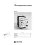
 The information in this user's manual is subject to change without notice.
WARNING
ONLY QUALIFIED ELECTRICAL PERSONNEL WHO ARE FAMILIAR WITH THE
CONSTRUCTION AND OPERATION OF THIS EQUIPMENT AND THE HAZARDS
INVOLVED SHOULD INSTALL, ADJUST, OPERATE, AND/OR SERVICE THIS
EQUIPMENT. READ AND UNDERSTAND THIS MANUAL IN ITS ENTIRETY
BEFORE PROCEEDING. FAILURE TO OBSERVE THIS PRECAUTION COULD
RESULT IN SEVERE BODILY INJURY.
WARNING
INSERTING OR REMOVING THIS PRODUCT OR ITS CONNECTING CABLES MAY
RESULT IN UNEXPECTED MACHINE MOTION. POWER TO THE MACHINE
SHOULD BE TURNED OFF BEFORE INSERTING OR REMOVING THE PRODUCT
OR ITS CONNECTING CABLES. FAILURE TO OBSERVE THIS PRECAUTION
COULD RESULT IN BODILY INJURY.
AutoMax, AutoMate, and Reliance are registered trademarks of Reliance Electric
ąąCompany or its subsidiaries.
Belden is a registered trademark of Belden, Inc.
Table of Contents
1.0
Introduction . . . . . . . . . . . . . . . . . . . . . . . . . . . . . . . . . . . . . . . . . . . . . . . 1Ć1
1.1 Additional Information . . . . . . . . . . . . . . . . . . . . . . . . . . . . . . . . . . . . 1Ć1
1.2 Related Hardware and Software . . . . . . . . . . . . . . . . . . . . . . . . . . . 1Ć2
2.0
Mechanical/Electrical Description . . . . . . . . . . . . . . . . . . . . . . . . . . . 2Ć1
2.1 Mechanical Description . . . . . . . . . . . . . . . . . . . . . . . . . . . . . . . . . . . 2Ć1
2.2 Electrical Description . . . . . . . . . . . . . . . . . . . . . . . . . . . . . . . . . . . . . 2Ć3
3.0
Installation . . . . . . . . . . . . . . . . . . . . . . . . . . . . . . . . . . . . . . . . . . . . . . . .
3.1 Wiring . . . . . . . . . . . . . . . . . . . . . . . . . . . . . . . . . . . . . . . . . . . . . . . . . .
3.2 InitialăInstallation . . . . . . . . . . . . . . . . . . . . . . . . . . . . . . . . . . . . . . . .
3.3 Module Replacement . . . . . . . . . . . . . . . . . . . . . . . . . . . . . . . . . . . . .
3Ć1
3Ć1
3Ć2
3Ć6
4.0
Programming . . . . . . . . . . . . . . . . . . . . . . . . . . . . . . . . . . . . . . . . . . . . . .
4.1 Analog Rail Module in AutoMate Systems . . . . . . . . . . . . . . . . . . .
4.1.1 Configuring the AutoMate Processor for
Use with the Analog Rail Module . . . . . . . . . . . . . . . . . . . . .
4.1.2 AutoMate Programming in Rail Mode . . . . . . . . . . . . . . . . .
4.1.3 AutoMate Programming in Local Head Mode . . . . . . . . . .
4.1.4 Analog In (AIN) and Analog Out (AOUT)
Instruction Blocks . . . . . . . . . . . . . . . . . . . . . . . . . . . . . . . . . .
4.2 Analog Rail Module in DCS 5000/AutoMax Systems . . . . . . . . . .
4.2.1 Configuring the Analog Rail Module with a
DCS 5000/AutoMax Remote I/O Head . . . . . . . . . . . . . . . .
4.2.2 Configuring the Analog Rail Module with a
Power Module Interface Processor Host . . . . . . . . . . . . . . .
4.2.3 DCS 5000/AutoMax Programming . . . . . . . . . . . . . . . . . . . .
4Ć1
4Ć1
4Ć11
4Ć11
Diagnostics and Troubleshooting . . . . . . . . . . . . . . . . . . . . . . . . . . . .
5.1 Both LEDs on the Faceplate are Off . . . . . . . . . . . . . . . . . . . . . . . .
5.2 The COM OK" LED is Off . . . . . . . . . . . . . . . . . . . . . . . . . . . . . . . . .
5.3 Incorrect Data . . . . . . . . . . . . . . . . . . . . . . . . . . . . . . . . . . . . . . . . . . .
5.4 Constant UnderĆRange . . . . . . . . . . . . . . . . . . . . . . . . . . . . . . . . . . .
5Ć1
5Ć1
5Ć3
5Ć3
5Ć4
5.0
4Ć2
4Ć7
4Ć8
4Ć9
4Ć10
4Ć10
I
Figure 1.1
Ć Analog Rail Module Hardware Configuration . . . . . . . . . . . . . . 1Ć3
Figure 2.1
Figure 2.2
Figure 2.3
Ć Analog Rail Module Faceplate . . . . . . . . . . . . . . . . . . . . . . . . . . 2Ć2
Ć Typical Output Circuit . . . . . . . . . . . . . . . . . . . . . . . . . . . . . . . . . . 2Ć4
Ć Typical Input Circuit . . . . . . . . . . . . . . . . . . . . . . . . . . . . . . . . . . . 2Ć4
Figure 3.1
Figure 3.2
Ć Mounting Dimensions . . . . . . . . . . . . . . . . . . . . . . . . . . . . . . . . . 3Ć2
Ć Typical Recommended Input and Output Shielding
Methods . . . . . . . . . . . . . . . . . . . . . . . . . . . . . . . . . . . . . . . . . . . . . 3Ć5
Figure 4.1
Figure 4.2
4Ć1
Ć Input Signal Conversion . . . . . . . . . . . . . . . . . . . . . . . . . . . . . . .
Ć Configuration for Analog Rail Module
with AutoMate 20 . . . . . . . . . . . . . . . . . . . . . . . . . . . . . . . . . . . . .
Figure 4.3 Ć Sample Configurations for Analog Rail Module
Connected Directly to AutoMate 30 or 40 . . . . . . . . . . . . . . . . .
Figure 4.4 Ć Sample Configuration for Analog Rail Module Connected
to AutoMate 30 or 40 Through Local I/O Head . . . . . . . . . . . .
Figure 4.5 Ć Sample Configuration for Analog Rail Module with
AutoMate Local I/O Processor . . . . . . . . . . . . . . . . . . . . . . . . . .
Figure 4.6 Ć Sample Configuration for Analog Rail Module with
AutoMate Remote I/O Head . . . . . . . . . . . . . . . . . . . . . . . . . . . .
Figure 4.7 Ć Rail Mode Register Image for Input Channels . . . . . . . . . . . . .
Figure 4.8 Ć Rail Mode Register Image for Output Channels . . . . . . . . . . .
Figure 4.9 Ć Local Head Mode Register Image for Input Channels . . . . . .
Figure 4.10 Ć Local Head Mode Register Image for Output Channels . . . .
Figure 4.11 Ć AIN Instruction Block . . . . . . . . . . . . . . . . . . . . . . . . . . . . . . . . . .
Figure 4.12 Ć AOUT Instruction Block . . . . . . . . . . . . . . . . . . . . . . . . . . . . . . . .
Figure 5.1
Figure 5.2
4Ć2
4Ć3
4Ć4
4Ć5
4Ć6
4Ć7
4Ć7
4Ć8
4Ć8
4Ć9
4Ć10
Ć Disassembling the Module to Replace the 32mA Fuse . . . . . 5Ć5
Ć Replacing the 32mA Fuse . . . . . . . . . . . . . . . . . . . . . . . . . . . . . . 5Ć6
III
fafadfdfdasfdsfdsdsdfdsfdsfdsfsdfdsa
afdfdsfdsfdfdsfdsfsadfda
asfdfaddfdd
1.0 INTRODUCTION
The products described in this instruction manual are manufactured
by Reliance Electric Industrial Company.
The 2ĆIn/2ĆOut 4Ć20mA Analog Rail module allows you to connect
two input and two output 4Ć20mA analog signals to AutoMater,
AutoMaxr and DCS 5000 systems. Typically, the Analog Rail module
is used with potentiometers, valve actuators, pressure or flow
transducers, and meters in both drive control systems and process
control systems.
The Analog Rail module is hardwareĆconfigurable by means of a
faceplate switch to emulate one of two types of devices, AutoMate
Rails or AutoMate Local Heads. In some hardware configurations,
the type of interface device available for the Analog Rail module will
determine the mode of operation that can be selected (see
figure 1.1).
The Analog Rail module operates in Local Head mode when it is
connected directly to one of the processor's four I/O ports in
AutoMate systems, to an AutoMate Local I/O Processor, or to one of
the four I/O ports of the DCS 5000/AutoMax Remote I/O Head in
DCS 5000/AutoMax systems. The Analog Rail data will take up four
registers in the host when operating in Local Head mode.
The module operates in Rail mode when it is connected to one I/O
port of a Local I/O Head, which in turn is connected to one I/O port
of an AutoMate processor. The Analog Rail module will occupy one
register of the host in Rail mode. The Rail mode is used to expand
the I/O address space available through the front I/O port of the
processor by multiplexing each group of four analog points through
one register. Note that the Analog Rail module cannot be used with
the Local I/O Head in DCS 5000/AutoMax systems.
The Analog Rail module operates in Rail mode when it is connected
to one I/O port of the Power Module Interface (PMI) Processor
(B/M 60000), which is in turn connected to a Universal Drive
Controller (UDC) module (M/N 57552) which resides in an AutoMax
rack.
The remainder of this manual describes the functions and
specifications of the module. It also includes a detailed overview of
installation and troubleshooting procedures, as well as examples of
configuration and programming.
1.1
Additional Information
You must become familiar with the instruction manuals which
describe your system configuration. This may include, but is not
limited to, the following:
D JĆ3031
AutoMate 30 PROCESSOR HARDWARE INSTRUCTION
MANUAL
D JĆ3033
AutoMate LOCAL I/O PROCESSOR INSTRUCTION
MANUAL
D JĆ3037
AutoMate REMOTE I/O HEAD INSTRUCTION MANUAL
D JĆ3063
AutoMate PROGRAMMING EXECUTIVE INSTRUCTION
MANUAL
1Ć1
JĆ3120
AutoMate 20 USER'S MANUAL
JĆ3141
AutoMate 40 CONTROL PROCESSOR INSTRUCTION
MANUAL
JĆ3150
AutoMate 30/40 SOFTWARE REFERENCE MANUAL
JĆ3649
DCS 5000/AutoMax CONFIGURATION TASK
INSTRUCTION MANUAL
JĆ3630
AutoMax PROGRAMMING EXECUTIVE INSTRUCTION
MANUAL
JĆ3600
DCS 5000 ENHANCED BASIC LANGUAGE
INSTRUCTION MANUAL
JĆ3675
AutoMax ENHANCED BASIC LANGUAGE
INSTRUCTION MANUAL
JĆ3601
DCS 5000 CONTROL BLOCK LANGUAGE
INSTRUCTION MANUAL
JĆ3676
AutoMax CONTROL BLOCK LANGUAGE
INSTRUCTION MANUAL
JĆ3602
DCS 5000 CONTROL BLOCK LANGUAGE
INSTRUCTION MANUAL
JĆ3677
AutoMax LADDER LOGIC LANGUAGE INSTRUCTION
MANUAL
JĆ3671
AutoMate LOCAL I/O HEAD INSTRUCTION MANUAL
JĆ3750
ReSource AutoMax PROGRAMMING EXECUTIVE
INSTRUCTION MANUAL VERSION 3.0
J2Ć3045 AutoMax PROGRAMMING EXECUTIVE VERSION 3.3
SĆ3006
DĆC DRIVE CONFIGURATION AND PROGRAMMING
INSTRUCTION MANUAL
SĆ3008
POWER MODULE INTERFACE RACK INSTRUCTION
MANUAL
Your personal computer and DOS operating system manual(s).
IEEE 518 GUIDE FOR THE INSTALLATION OF ELECTRICAL
EQUIPMENT TO MINIMIZE ELECTRICAL NOISE INPUTS TO
CONTROLLERS
1Ć2
The 2ĆIn/2ĆOut 4Ć20mA Analog Rail module, M/N 61C351, contains
the following:
1. One 2ĆIn/2ĆOut 4Ć20mA Analog Rail module
2. One I/O Rail cable: M/N 45C5
3. Two plug connectors: 12Ćpoint connector part no. 419434Ć2R
ă4Ćpoint connector part no. 419434Ć1R
4. One .25A fuse (installed in the module): part no. 64676Ć23J
5. One .75A fuse (required for operation on 24 VDC):
part no. 64676Ć23Q
6. Two cable retainer clips
7. Two 32mA fuses (installed in the module): part no. 64676Ć44A
8. Two spare 32mA fuses: part no. 64676Ć44A
The Analog Rail module can be configured with the hardware
(purchased separately) listed in figure 1.1.
DCS 5000/AutoMax
Remote I/O Head
M/N 57C330
Local Head
AutoMate 20, 20E
M/N 45C20, 45C21,
45C220, 45C221,
45C224, 45C225
Local Head or Rail *
AutoMate 30, 30E
M/N 45C301, 45C305,
45C307
Local Head or Rail *
AutoMate 40, 40E
M/N 45C410, 45C411
Local Head or Rail *
AutoMate Local
I/O Processor
M/N 45C200B
(and later versions)
Local Head
AutoMate
Remote I/O Head
M/N 45C37, 45C38
Local Head
Power Module
Interface Processor
B/M 60000
Rail
* Direct connection to the Processors (Local Head mode) or connection
through an AutoMate Local I/O Head, M/N 45C22, 61C22, 61C22A, or
61C23 (Rail mode). Note that it is also permissible to configure the Analog
Rail module for Rail mode even if it is connected directly to an AutoMate
20, 30, or 40 Processor.
Figure 1.1 Ć Analog Rail Module Hardware Configuration
1Ć3
fafadfdfdasfdsfdsdsdfdsfdsfdsfsdfdsa
afdfdsfdsfdfdsfdsfsadfda
asfdfaddfdd
2.0 MECHANICAL/ELECTRICAL
DESCRIPTION
The following sections describe the mechanical and electrical
characteristics of the Analog Rail module.
2.1
Mechanical Description
The Analog Rail module is a selfĆcontained electronic module
containing two input channels multiplexed to an analogĆtoĆdigital
converter and a dual digitalĆtoĆanalog converter for two output
channels. The module is housed in a protective metal enclosure
designed for panel mounting. See figure 2.1.
2Ć1
Analog Rail
61C351
4 to 20 mA IN/OUT
Input
PWR COM
OK
OK
Local
Head
Mode
Rail
Analog I/O
IĆOUT
CH
0
CH
1
Common
IĆOUT
Common
IĆIN
CH
2
CH
3
Common
IĆIN
Common
Input Power
DCDC+
L2
L1
24
VDC
120
VAC
Fuse Type
250V MDQ
24 VDC:
Use 0.75A
120 VAC:
Use 0.25A
GND
Figure 2.1 Ć Analog Rail Module Faceplate
2Ć2
The faceplate of the module contains three electrical connectors
labeled Input", Analog I/O", and Input Power" (reading top to
bottom). The top connector is used for connection to the I/O port. A
cable (M/N 45C5) is provided for this purpose. The second
connector, labeled Analog I/O", is a numbered, 12Ćpoint removable
plug connector with screwĆtype terminal points. Three successive
terminal points are reserved for each channel's connection to
external hardware. The top 6 points are reserved for the two output
channels (channel 0 and channel 1) and the bottom 6 are reserved
for the two input channels (channel 2 and channel 3). The Analog
I/O" terminals are designed for 14Ć22 AWG wire.
The third connector on the faceplate, also a removable plug
connector with screwĆtype terminal points, is used for input power.
The terminal points are labeled. The top two points are used if the
power source is 24 VDC. The bottom two points are used if the
power source is 120 VAC. The Input Power" terminals are designed
to use 14 AWG wire. A terminal stud for connecting a grounding
conductor is provided on the bottom of the rightĆhand mounting
flange.
The module faceplate also contains two LEDs, a mode switch, and a
fuse holder and fuse. The LED labeled PWR OK" indicates that the
I/O port, the external power source, and the internallyĆgenerated
voltages necessary for operation of the module are present. The
COM OK" LED indicates whether all four channels are successfully
communicating with the host.
The switch labeled Mode" is used to select between Local Head"
and Rail" mode. Note that the position of the switch is read only
once at the time power is turned on to the Reliance device that is
connected to the Analog Rail module. The mode will remain fixed as
long as this device is powered up.
As shipped from the factory, the fuse holder on the bottom of
the faceplate contains a .25A fuse for 120 VAC input power. If
input power will be 24 VDC, you need to replace the fuse with
the .75A fuse included along with the Analog Rail module.
2.2
Electrical Description
The Analog Rail module contains two analog input channels that
convert 4Ć20mA analog input signals to proportional values between
0 and 4095, equal to 12 bits of digital data. Input channels are
protected with a 32mA userĆreplaceable fuse. Input signals are
filtered through a second order lowĆpass filter. The module also
contains two output channels that can output 4Ć20mA analog
signals proportional to an input value of 0 to 4095. A userĆsupplied
power supply in series with the external hardware is required for the
output channels. Note that at a digital output = 4096, the output
rolls over to zero again. Negative output values cannot be
accommodated.
The A/D and D/A conversions are triggered by the actual I/O update
sequences. The conversion rate is therefore dependent upon the
scan time of the application task. See figure 2.2 for a typical output
circuit. See figure 2.3 for a typical input circuit.
2Ć3
DAC
RFB
IĆOUT
0.416 2.083 V
+10.000 V
104.167
I-OUT
Figure 2.2 Ć Typical Output Circuit
+10.000 V
to A/D
converter
IĆIN
32 mA
( 250 )
277.778 IĆCommon
Figure 2.3 Ć Typical Input Circuit
The Analog Rail module is factory calibrated and requires no
offset/gain adjustment. All four analog I/O channels are referenced
to the same common. This common is isolated from both the
external power supply and the I/O port connection.
The module incorporates extensive diagnostics. In Rail mode, check
bits are monitored for accuracy on every transfer of data between
the processor and the module. In Local Head mode, parity bits are
monitored for accuracy on every transfer of data. A Rail fault LED on
the processor, Remote Head, or Local Head will be illuminated if the
check bits or parity bits are wrong and all transmission will stop after
n retries, where n is a value determined by the host's software
(average n = 4 for AutoMax; AutoMate n = 2).
In the event of a rail fault, all outputs will be set to 0. The COM OK"
LED on the module will go off. If any power required by the module,
i.e., the +5 Volts from the I/O port required for communication, the
external power supply, or the power required by the Analog I/O
section, is not within specified limits, all outputs will be set to 0 and
the PWR OK" LED will go off.
2Ć4
3.0 INSTALLATION
This section describes how to install and replace the Analog Rail
module. Note that analog signals are sensitive to variations in
temperature. The Analog Rail module is designed to perform
optimally at room temperature, approximately 25oC. In all cases, the
ambient temperature of the installation must be maintained in the
range specified in Appendix A to ensure the highest possible
accuracy.
DANGER
THE USER IS RESPONSIBLE FOR CONFORMING WITH THE NATIONAL
ELECTRICAL CODE AND ALL OTHER APPLICABLE LOCAL CODES. WIRING
PRACTICES,
GROUNDING,
DISCONNECTS,
AND
OVERĆCURRENT
PROTECTION ARE OF PARTICULAR IMPORTANCE. FAILURE TO OBSERVE THIS
PRECAUTION COULD RESULT IN SEVERE BODILY INJURY OR LOSS OF LIFE.
DANGER
DO NOT TOUCH THE CONNECTORS ON THE FACEPLATE IF THERE IS POWER
ON THE WIRES ATTACHED TO THE PLUG CONNECTOR SCREW TERMINALS.
ALWAYS TURN OFF POWER BEFORE HANDLING A CONNECTOR THAT IS
WIRED. FAILURE TO OBSERVE THIS PRECAUTION COULD RESULT IN SEVERE
BODILY INJURY OR LOSS OF LIFE.
WARNING
UNEXPECTED OUTPUT CHANGES MAY RESULT IF AN ANALOG RAIL IS
PLUGGED INTO A LOCAL I/O HEAD THAT IS COMMUNICATING WITH A
PROCESSOR. ANY HARDWARE CONFIGURATION CHANGES MUST BE MADE
ONLY WITH THE LOCAL I/O INTERFACE CABLE (M/N 45C8) DISCONNECTED.
FAILURE TO OBSERVE THIS PRECAUTION COULD RESULT IN BODILY INJURY.
CAUTION
THE ANALOG RAIL MODULE IS DESIGNED TO BE POWERED BY EITHER 24 VDC
OR 120 VAC. CONNECT THE PROPER POWER SOURCE TO THE MODULE.
FAILURE TO OBSERVE THIS PRECAUTION COULD RESULT IN DAMAGE TO OR
DESTRUCTION OF THE EQUIPMENT.
3.1
Wiring
To reduce the possibility of electrical noise interfering with the
proper operation of the control system, exercise care when installing
the wiring between the module and the external hardware.
Use shielded twisted pair for all wiring between the Analog Rail
module and the external hardware. Belden 8761 or an equivalent
cable type is recommended. For detailed recommendations refer to
IEEE 518.
3Ć1
Use the following procedure to install the Analog Rail module.
Step 1.
Using the mounting dimensions shown in figure 3.1,
prepare the necessary mounting provisions on the panel.
The module is designed to be mounted vertically using
four #10 or M5 bolts or studs. Multiple modules should
be mounted side by side. The flange width of two
modules side by side is sufficient to dissipate the heat
produced by the modules. The modules can also be
mounted one above the other, but since this hardware
configuration does not allow the most efficient heat
dissipation, the minimum clearance between the module
chassis is 3". See figure 3.1.
2.44"
7.0"
9.25"
2.94"
3.0"
Depth: 7.75"
Diameter of mounting holes: 7/32"
Figure 3.1 Ć Mounting Dimensions
3Ć2
Step 2.
If the power supply you are using is 24 VDC, replace the
factoryĆinstalled .25A fuse with the .75A fuse that came in
the shipping box with the module. Use a screwdriver to
release the fuse holder located on the Analog Rail
module faceplate. Pull the fuse holder out of the module.
Take the .25A fuse out of the fuse holder and replace it
with the .75A fuse. ReĆinsert the fuse holder into the
module. Turn the screwdriver clockwise while pressing
down on the fuse holder. The fuse holder must be flush
against the faceplate.
Step 3.
Mount the Analog Rail on the panel and attach it securely
to the wall with #10 (M5) studs or bolts.
Step 4.
Make certain that no voltage is present on the wires that
will be used to provide 120 VAC or 24 VDC power to the
Analog Rail module. Use either a 120 VAC or 24 VDC
power supply, but not both.
Step 5.
Using 14 AWG wire, connect input power to the screw
terminals on the Input Power" plug connector on the
faceplate as shown below. Strip off approximately 5/16"
of insulation from the wires.
24 VDC Power
Signal
24 VDC 24 VDC +
Terminal Label
DCDC+
Terminal Number
1
2
120 VAC Power
Signal
120 VAC - (neutral)
120 VAC + (hot)
Step 6.
Terminal Label
L2/N
L1
Terminal Number
3
4
Use the stud marked GND" (ground) on the bottom right
flange of the module to connect a ground wire.
DANGER
THE USER IS RESPONSIBLE FOR CONFORMING WITH THE NATIONAL
ELECTRICAL CODE AND ALL OTHER APPLICABLE LOCAL CODES. WIRING
PRACTICES,
GROUNDING,
DISCONNECTS,
AND
OVERĆCURRENT
PROTECTION ARE OF PARTICULAR IMPORTANCE. FAILURE TO OBSERVE THIS
PRECAUTION COULD RESULT IN SEVERE BODILY INJURY OR LOSS OF LIFE.
Step 7.
Turn off all power to any external hardware that will
provide input signals to the module or be powered by the
module.
Step 8.
Attach a retainer clip to the connector at each end of the
I/O Rail cable (M/N 45C5). Note that faceplate connectors
have slots that correspond to the part of the retainer clip
that protrudes away from the cable connector. The
retainer clip is used to assure a tight connection between
the cable and faceplate connectors.
Step 9.
Using 14Ć22AWG wire, connect external hardware to the
Analog I/O" plug connector on the faceplate as shown
below. Strip off approximately 5/16" insulation from the
wires.
3Ć3
0
1
2
3
IĆOUT
Common
(no label)
4-20mA+ output
common
(shield; no connection)*
1
4
5
6
IĆOUT
Common
(no label)
4-20mA+ output
common
(shield; no connection)*
2
7
8
9
IĆIN
Common
(no label)
4-20mA+ input
common
(shield; no connection)*
3
10
11
12
IĆIN
Common
(no label)
4-20mA+ input
common
(shield; no connection)*
*This terminal makes no electrical connection to the Analog Rail printed circuit
board.
3Ć4
Step 10.
For each of the two output channels, connect a shield
wire from the external hardware to the third terminal
(terminals 3 and 6, respectively). The shield wire at the
external hardware end of the cable should be connected
to the source reference point. See figure 3.2.
Step 11.
For each of the two input channels, connect a shield wire
from the external hardware to the third terminal (terminals
9 and 12, respectively). The shield wire at the external
hardware end of the cable should be connected to the
source reference point. See figure 3.2.
Channel 0
IĆOut
1
Source
Load
-
+
Common 2
+
-
3
Channel 1
IĆOut
4
Source
Load
-
+
Common 5
+
-
6
Source
Channel 2
IĆIn
7
Common 8
+
-
9
Source
Channel 3
IĆIn
10
Common 11
+
-
12
Figure 3.2 Ć Typical Recommended Input and Output Shielding Methods
Step 12.
Turn off power to the Reliance device that will be
connected to the Analog Rail module.
Step 13.
Set the Mode" switch on the faceplate of the Analog Rail
module to the desired position.
Step 14.
Connect the I/O Rail cable between the Analog Rail
connection labeled Input" and an I/O port on the
Reliance device that will communicate with the module.
Turn on power to the Reliance device that will
communicate with the Analog Rail module. Recall that the
Mode switch is read each time the Reliance device
connected to the module is powered up.
Step 15
The Analog Rail installation is now ready for testing.
Inspect all work to assure that the installation has been
performed properly.
Step 16.
Turn on power to the Input Power" wiring. Turn on power
to the external hardware. Recall that external hardware
being powered by the output of the Analog Rail module
must be in series with an external power supply. See
figure 3.2. See Appendix A for the power supply
specifications.
3Ć5
Step 17.
Verify that the hardware has been installed correctly.
Before testing, insure that the external hardware will not
respond to output signals from the Analog Rail module.
WARNING
BE CAREFUL WHEN WRITING TO THE OUTPUTS TO INSURE THAT NO
UNEXPECTED MACHINE MOTION WILL RESULT. FAILURE TO OBSERVE THIS
PRECAUTION COULD RESULT IN BODILY INJURY OR DAMAGE TO EQUIPMENT.
For AutoMate systems, you must configure the AutoMate
processor using the AutoMate Programming Executive
(APX) before testing. See section 4.0 for more
information. After configuring the module, use the APX
Point Monitor function to test the module. You can test the
Analog Rail module output channels by writing a value
between 0 and 4095 to those channels and, with an
ammeter, verifying that the output on the terminal points
(4Ć20mA) is proportional. To test input channels, verify
that the input signal in the channel (4Ć20mA) is
proportional to an ammeter reading at the terminal points.
For DCS 5000, AutoMax, or Distributed Power DĆC Drive
systems, use the DCS 5000 or AutoMax Programming
Executive software I/O Monitor function, respectively. Test
output channels by writing a value between 0 and 4095 to
those channels and using an ammeter to verify that the
signal on the terminal points (4Ć20mA) is proportional. To
test input channels, verify that the input signal in the
channel (4Ć20mA) is proportional to a ammeter reading at
the terminal points.
3.3
Module Replacement
Use the following procedure to replace the module.
3Ć6
Step 1.
Stop any application programs that are running.
Step 2.
Turn off power to the external hardware connected to the
input and output channels on the faceplate of the
module.
Step 3.
Turn off power to the Analog Rail module (120 VAC or
24 VDC).
Step 4.
Turn off power to the Reliance device connected to the
Analog Rail module.
Step 5.
Disconnect the I/O Rail cable from the Analog Rail
module.
Step 6.
Without disconnecting the wiring, remove the 12Ćpoint
terminal from the faceplate and set aside.
Step 7.
Without disconnecting the wiring, remove the 4Ćpoint
terminal from the faceplate and set aside. Disconnect the
ground wire from the bottom of the rightĆhand flange.
Step 8.
Loosen the screws that hold the Analog Rail module to
the panel and remove the module.
Step 9.
If the power supply you are using is 24 VDC, you need to
replace the factoryĆinstalled .25A fuse in the new module
with the .75A fuse that came in the shipping box with the
module. Use a screwdriver to release the fuse holder
located on the Analog Rail module faceplate. Pull the fuse
holder out of the module.
Remove the .25A fuse from the fuse holder and replace it
with the .75A fuse. ReĆinsert the fuse holder into the
module. Turn the screwdriver clockwise while pressing
down on the fuse holder at the same time. The fuse
holder must be flush against the faceplate.
Step 10.
Remove the two plug connectors from the faceplate of
the new module by pulling them firmly away from the
faceplate.
Step 11.
Place the new module over the pattern drilled and attach
it securely to the panel with #10 or M5 studs or bolts.
Step 12.
Attach the original 12Ćpoint and 4Ćpoint connectors with
wiring to the faceplate of the module. Use the stud
marked GND" (ground) on the bottom right flange of the
module to connect a ground wire.
Step 13.
Set the Mode" switch on the faceplate to the desired
position.
Step 14.
Connect the I/O Rail cable between the Analog Rail
connection labeled Input" and the I/O port. Turn on
power to the Reliance device connected to the Analog
Rail module. Recall that the Mode switch is read each
time the Reliance device connected to the module is
powered up. If applicable, reĆconnect the cable between
the Local I/O Head, or the DCS 5000 Remote I/O Head,
and the host.
Step 15.
Turn on power to the Analog Rail module Input Power"
connections.
Step 16.
Turn on power to the external hardware connected to the
Analog Rail module.
Step 17.
Verify that the hardware has been installed correctly.
Before testing, insure that the external hardware cannot
respond to output signals from the Analog Rail module.
WARNING
BE CAREFUL WHEN WRITING TO THE OUTPUTS TO INSURE THAT NO
UNEXPECTED MACHINE MOTION WILL RESULT. FAILURE TO OBSERVE THIS
PRECAUTION COULD RESULT IN BODILY INJURY OR DAMAGE TO EQUIPMENT.
For AutoMate systems, use the APX Point Monitor
function to test the module. You can test the Analog Rail
module output channels by writing a value between 0 and
4095 to those channels and, with an ammeter, verifying
that the output on the terminal points (4Ć20mA) is
proportional. To test input channels, verify that the input
signal in the channel (4Ć20mA) is proportional to an
ammeter reading at the terminal points.
3Ć7
For DCS 5000, AutoMax, or Distributed Power DĆC Drive
systems, use the DCS 5000 or AutoMax Programming
Executive software I/O Monitor function, respectively. Test
output channels by writing a value between 0 and 4095 to
those channels and using an ammeter to verify that the
signal on the terminal points (4Ć20mA) is proportional. To
test input channels, verify that the input signal in the
channel (4Ć20mA) is proportional to an ammeter reading
at the terminal points.
3Ć8
This section describes how the data is organized in the module and
provides examples of how the module is accessed by application
programs.
When creating application programs, the programmer must estimate
the magnitude of input signals and output data because both must
be in the specified range of the Analog Rail module (4Ć20mA). Input
signals greater than 20mA will be clamped at 4095. Signals greater
than approximately 22.6mA will also cause the overĆrange bit (12
decimal; 14 octal) to be set to 1. Input signals less than 4mA are
clamped at zero (0). Signals less than approximately 2.5mA will also
cause the underĆrange bit (13 decimal; 15 octal) to be set to 1. See
figure 4.1.
Counts
>22.6 = overĆrange
4095
0
4
<2.5 = underĆrange
20
mA
Figure 4.1 Ć Input Signal Conversion
Recall that at a digital output = 4096, the output rolls over to zero
again. The programmer must include limits in the application
software to ensure that the data sent to output channels is always in
the specified range (allowable range = 0 to 4095).
This section describes how the Analog Rail is used with AutoMate
systems. Local Head mode allows all four channels on the module
to be updated at the end of the scan (normal I/O update rate in this
configuration), or during the scan using AIN and AOUT blocks (see
section 4.1.4). Rail mode allows only one channel to be updated at
the end of the scan (normal I/O update rate in this configuration), or
all four channels to be updated during the scan if AIN and AOUT
blocks are used.
4Ć1
Configuration is the process of describing in software how the
hardware and software in the system are related. The Analog Rail
module is configured using the AutoMate Programming Executive
(APX) software, M/N 45C130 or 45C131. Select CONFIGURE
SYSTEM from the main menu to create the configuration.
Note that the Analog Rail module can also be configured using the
AutoMate Programming System (APS) software, M/N 45C134,
45C141, 45C142, or 45C143. Refer to instruction manual J2Ć3041 for
additional information.
The Analog Rail module is configured depending upon the mode in
which it is being used. See figures 4.2, 4.3, 4.4, 4.5, and 4.6 for how
to configure the Analog Rail for use with AutoMate processors. The
sample configurations are shown as they appear on the APX screen.
Unless otherwise noted, all references to the AutoMate 20, 30, and
40 will also apply to the 20E, 30E and the 40E, respectively.
Analog Rail Module with AutoMate 20
(Local Head Mode or Rail Mode)
AutoMate 20 registers reserved for port configuration:
2734
2735
2736
2737
Port 0 of AutoMate 20
Port 1 of AutoMate 20
Port 2 of AutoMate 20
Port 3 of AutoMate 20
Local Head Mode
Enter the value 64XX for the register representing the port to which the Analog
Rail module is connected, where XX is a value from 00Ć14*. The XX value repreĆ
sents the first register in a set of four contiguous registers that will be used to
store data for the port.
Rail Mode
Enter the value 16XX for the register representing the port to which the Analog
Rail module is connected, where XX is a value from 00Ć17*. The XX value repreĆ
sents the register that will be used to multiplex data through the I/O port.
*Values are in octal notation.
Figure 4.2 Ć Configuration for Analog Rail Module with AutoMate 20
4Ć2
Analog Rail Module Connected Directly to AutoMate 30 or 40
(Local Head Mode or Rail Mode)
The following sample configuration shows two Analog Rail modules connected
directly to an AutoMate 30 or 40 Processor in Local Head mode:
MSLT DROP TYP RSLT CARD CH0 REGISTER CH1 REGISTER CH2 REGISTER CH3 REGISTER
ă1
A/M
LHD ăă0Ć3
LHD ăă4Ć7
NU
NU
The following sample configuration shows two Analog Rail modules connected
directly to an AutoMate 30 or 40 Processor in Rail Mode :
MSLT DROP TYP RSLT CARD CH0 REGISTER CH1 REGISTER CH2 REGISTER CH3 REGISTER
ă1
A/M
RAIL ăăă0
RAIL ăăăă1
NU
NU
Figure 4.3Ć Sample Configurations for Analog Rail Module
Connected Directly to AutoMate 30 or 40
4Ć3
Analog Rail Module Connected to AutoMate 30 or 40 Through a Local I/O Head
(Rail Mode Only)
The following sample configuration shows two Analog Rail modules connected to
an AutoMate 30 or 40 through a Local I/O Head:
MSLT DROP TYP RSLT CARD CH0 REGISTER CH1 REGISTER CH2 REGISTER CH3 REGISTER
ă2
A/M
LHD ăăă0Ć3
NU
NU
NU
Figure 4.4 Ć Sample Configuration for Analog Rail Module Connected
to AutoMate 30 or 40 Through Local I/O Head
4Ć4
Analog Rail Module with AutoMate Local I/O Processor (Local Head Mode Only)
The following sample configuration shows three Analog Rail modules connected
to a Local I/O Processor in a remote rack:
MSLT DROP TYP RSLT CARD CH0 REGISTER CH1 REGISTER CH2 REGISTER CH3 REGISTER
ă2
ă1
RRK ăă2 LIOP LHD ăăă0Ć3
LHD ăăă4Ć7
LHD ăă10Ć13
NU
Figure 4.5 Ć Sample Configuration for Analog Rail Module
with AutoMate Local I/O Processor
4Ć5
Analog Rail Module with AutoMate Remote I/O Head (Local Head Mode Only)
The following sample configuration shows one Analog Rail module connected to
an AutoMate Remote I/O Head:
MSLT DROP TYP RSLT CARD CH0 REGISTER CH1 REGISTER CH2 REGISTER CH3 REGISTER
ă1
ă0
RHD
LHD ăăă0Ć3
NU
NU
NU
Figure 4.6 Ć Sample Configuration for Analog Rail Module
with AutoMate Remote I/O Head
4Ć6
In Rail mode, the Analog Rail module is imaged in one I/O register of
the processor. Data from one of the four channels will occupy the
register as a function of the channel select bits. The active channel
is updated at the end of each scan. For input channels, the two
channel select bits in the register must be set to the appropriate
input channel number. After the I/O update, the register contains the
data in the format shown in figure 4.7. For output channels, the data
in the register must be in the format shown in figure 4.8 prior to the
I/O update.
Octal
MSB LSB ăCH#
ă0ąą0 = CH 0
ă0ąą1 = CH 1
ă1ąą0 = CH 2
ă1ąą1 = CH 3
17 16 15 14 13 12 11 10
7
6
5
4
3
2
1
0
1
0
12 bits of converted analog data
overĆrange (1=overĆrange)
underĆrange (1=underĆrange)
channel being read: LSB
channel being read: MSB
Figure 4.7 Ć Rail Mode Register Image for Input Channels
Octal
MSB LSB ăCH#
ă0ąą0 = CH 0
ă0ąą1 = CH 1
ă1ąą0 = CH 2
ă1ąą1 = CH 3
17 16 15 14 13 12 11 10
7
6
5
4
3
2
12 bits of analog output data
not used
not used
channel being modified: LSB
channel being modified: MSB
Figure 4.8 Ć Rail Mode Register Image for Output Channels
The Analog Rail module data may also be accessed in the middle of
the scan (as opposed to the end of the scan, which is the normal
mode of operation for digital rail I/O) using the appropriate number
of Analog In (AIN) and Analog Out (AOUT) blocks. The AIN block
will check whether the overĆrange or underĆrange bits have been set
by the module and the error coil will be energized, if applicable. The
AOUT block will set the channel select bits appropriately. See
section 4.1.4 for more information about the AIN and AOUT blocks.
Note that the AIN and AOUT blocks are supported by the AutoMate
20E M/N 45C224 and 45C225, but not the AutoMate 20 (M/N 45C20,
45C21, 45C220, 45C221) by APX Version 3.0.
4Ć7
For processors that do not support the AIN and AOUT blocks, you
can use the MOVE block to move data in and out of the registers
assigned and to determine the channel select bits. OverĆrange and
underĆrange bits should be used as inputs to error coils. The I/O
update will occur automatically at the end of each scan. See
Appendix C for a sample AutoMate program that writes to and reads
from the Analog Rail module without using AIN and AOUT blocks.
In Local Head mode, the module is imaged in four I/O registers of
the processor. Data from all four channels is always available and
will be updated at the end of each scan. For input channels, it is not
necessary to select the channel. After the I/O update, the register
contains the data in the format shown in figure 4.9. For output
channels, the data in the register must be in the format shown in
figure 4.10 prior to the I/O update.
Octal
17 16 15 14 13 12 11 10
7
6
5
4
3
2
1
0
12 bits of converted analog data
overĆrange (1=overĆrange)
underĆrange (1=underĆrange)
not used
not used
Figure 4.9 Ć Local Head Mode Register Image for Input Channels
Octal
17 16 15 14 13 12 11 10
7
6
5
4
3
2
1
0
12 bits of analog output data
not used
not used
not used
not used
Figure 4.10 Ć Local Head Mode Register Image for Output Channels
The Analog Rail module data may also be accessed in the middle of
the scan (as opposed to the end of the scan) using the appropriate
number of Analog In (AIN) and Analog Out (AOUT) blocks. The AIN
block will set the overĆrange or underĆrange bits if applicable. See
section 4.1.4 for more information about the AIN and AOUT blocks.
Note that the AIN and AOUT blocks are supported by the AutoMate
20E (M/N 45C224 and 45C225), but not the AutoMate 20 (M/N
45C20, 45C21, 45C220, 45C221) by APX Version 3.0.
4Ć8
For processors that do not support the AIN and AOUT blocks, you
can use the MOVE block to move data in and out of the registers
assigned. OverĆrange and underĆrange bits should be used as
inputs to error coils. The I/O update will occur automatically at the
end of each scan. See Appendix C for a sample AutoMate program
that writes to and reads from the Analog Rail module without using
AIN and AOUT blocks.
4.1.4
Analog In (AIN) and Analog Out (AOUT) Instruction
Blocks
The AIN and AOUT blocks are used, respectively, to read inputs
from and write outputs to the Analog Rail module. AIN and AOUT
blocks are supported for the 20E processor. The AIN and AOUT
blocks make it possible to update the channels on the Analog Rail
module during the scan instead of at the end of the scan (the
standard AutoMate I/O update). The blocks also make it possible to
update all four channels during the scan in Rail mode, a hardware
configuration which would otherwise allow only one channel on the
module to be updated. The format of the two blocks is shown in
figures 4.11 and 4.12.
AIN Instruction Block
The example below shows an AIN block for an Analog Rail module connected to
port 2 of an AutoMate Processor.
AIN
12
.01
[ ]
EN
AIN
IOPORT:
LHPORT:
CHAN:
DEST:
VALUE:
AutoMate 20E
with ports
0, 1, 2, and 3
0
1
2
3
IOPORT Ć
2
0
3
2000
EN
13
.01
( )
ER
76
.00
( )
Analog Rail with
channels 0, 1, 2, and 3
In Rail Mode
Chan 0
Chan 1
Chan 2
Chan 3
Processor port to which the Analog Rail is connected (directly or
indirectly); value range 0Ć3.
LHPORT Ć Local I/O Head port to which the Analog Rail is connected; value
range 0Ć3. If a Local I/O Head is not used, the value is 0.
CHAN Ć
Channels on the Analog Rail module to read; value range 2 or 3.
DEST Ć
Register number where the value of the channel is stored.
Figure 4.11 Ć AIN Instruction Block
4Ć9
AOUT Instruction Block
The example below shows an AOUT block for an Analog Rail module connected
to port 2 of a Local I/O Head, which in turn is connected to port 3 of an AutoMate
Processor. Data from register 2000 is used in this example.
AOUT
13
12
.01
.01
EN
EN
( )
[ ]
AOUT
SRC:
VALUE:
IOPORT:
LHPORT:
CHAN:
AutoMate 20E
with ports
0, 1, 2, and 3
0
1
2
3
Local Head
with ports
0, 1, 2, and 3
2000
3
2
1
ER
76
.00
( )
Analog Rail with
channels 0, 1, 2, and 3
In Rail Mode
0
1
2
3
Chan 0
Chan 1
Chan 2
Chan 3
SRC Ć
Register number from which the data to output will be taken.
IOPORT Ć
Processor port to which the Analog Rail is connected (directly or
indirectly); value range 0Ć3.
LHPORT Ć Local I/O Head port to which the Analog Rail is connected; value
range 0Ć3. If a Local I/O Head is not used, the value is 0.
CHAN Ć
Channel on the Analog Rail module to write; value range 0 or 1.
Figure 4.12 Ć AOUT Instruction Block
4.2
Analog Rail Module in DCS 5000/AutoMax
Systems
This section describes how the Analog Rail is used with
DCS 5000/AutoMax systems.
4.2.1
Configuring the Analog Rail Module with a
DCS 5000/AutoMax Remote I/O Head
The Analog Rail module is used in the Local Head mode when the
host is a DCS 5000/AutoMax Remote I/O Head. For AutoMax
Version 3.0 and later, the Analog Rail module is configured using the
AutoMax Programming Executive. Refer to instruction manual
JĆ3750 for more information. For DCS 5000 or AutoMax Version 2.1
or earlier, the module is defined in the configuration task for the
master rack using the DCS 5000 or AutoMax Programming
Executive software. See instruction manual JĆ3649 for more
information on the configuration task.
4Ć10
For DCS 5000 or AutoMax Version 2.1 or earlier, use the RIODEF
statement to define each channel on the Analog Rail module as a
separate register. Note that in addition to defining each channel as a
register, you can also define the overĆrange and underĆrange bits for
each channel separately. These bits can also be defined using the
RIODEF statement. Use the following format for the RIODEF
statement:
nnnnn RIODEF name[MASTER_SLOT=m, DROP=d, SLOT=s, REGISTER=r, BIT=b]
where:
nnnnn Ć Configuration task line number; range 1Ć32767.
name Ć Symbolic name of channel, ending with % (integer) for
registers, @ (booleans) for bits.
4.2.2
m
Ć Slot in rack containing DCS 5000/AutoMax master remote
I/O module; range 0Ć15.
d
Ć Drop number of DCS 5000/AutoMax Remote I/O Head;
range 1Ć7.
s
Ć Communication port on the DCS 5000/AutoMax
Remote I/O
Head to which the Analog Rail module is connected;
range 0Ć3.
r
Ć Register number; range 0Ć3.
b
Ć Optional field defining the bit position within the register
number; range 0Ć15.
Configuring the Analog Rail Module with a Power
Module Interface Processor Host
The Analog Rail module is used in the Rail mode when the host is a
Power Module Interface (PMI) Processor. Beginning with AutoMax
Version 3.3, the Analog Rail module is configured using the AutoMax
Programming Executive. Refer to instruction manual J2Ć3045 for
more information.
4.2.3
DCS 5000/AutoMax Programming
When programming the Analog Rail module, it is recommended that
you monitor the state of the overĆrange and underĆrange bits for the
input channels. You can check the status of the appropriate bits
directly if they were defined in the configuration. You can also use
the BASIC expression AND with the variable name assigned to the
input channel to mask off the 12 bits of analog data and read the
values in the overĆrange and underĆrange bits. Any nonĆzero result
means that the value is out of range. See the following three
statements for examples of how to detect values out of range. Use
the hexadecimal values shown to mask off the analog data.
The value in the channel defined as CHANNEL_2 is either
overĆrange or underĆrange:
10000 RANGE_ERROR@ = CHANNEL_2 AND 3000H
The value in the channel defined as CHANNEL_2 is overĆrange:
11000 OVER_ERROR@ = CHANNEL_2 AND 1000H
The value in the channel defined as CHANNEL_2 is underĆrange:
12000 UNDER_ERROR@ = CHANNEL_2 AND 2000H
4Ć11
fafadfdfdasfdsfdsdsdfdsfdsfdsfsdfdsa
afdfdsfdsfdfdsfdsfsadfda
asfdfaddfdd
5.0 DIAGNOSTICS AND
TROUBLESHOOTING
DANGER
THE REMAINING STEPS ARE MADE WITH POWER ON. EXERCISE EXTREME
CAUTION BECAUSE HAZARDOUS VOLTAGE EXISTS. FAILURE TO OBSERVE
THIS PRECAUTION COULD RESULT IN SEVERE BODILY INJURY OR LOSS OF
LIFE.
WARNING
ONLY QUALIFIED ELECTRICAL PERSONNEL FAMILIAR WITH THE
CONSTRUCTION AND OPERATION OF THIS EQUIPMENT AND THE HAZARDS
INVOLVED SHOULD INSTALL, ADJUST, OPERATE, AND/OR SERVICE THIS
EQUIPMENT. READ AND UNDERSTAND THIS MANUAL IN ITS ENTIRETY
BEFORE PROCEEDING. FAILURE TO OBSERVE THIS PRECAUTION COULD
RESULT IN BODILY INJURY.
WARNING
INSERTING OR REMOVING THIS PRODUCT OR ITS CONNECTING CABLES MAY
RESULT IN UNEXPECTED MACHINE MOTION. POWER TO THE MACHINE
SHOULD BE TURNED OFF BEFORE INSERTING OR REMOVING THE PRODUCT
OR ITS CONNECTING CABLES. FAILURE TO OBSERVE THIS PRECAUTION
COULD RESULT IN BODILY INJURY.
This section explains how to troubleshoot the Analog Rail module. If
you cannot correct the problem using the instructions below, the
unit is not userĆserviceable.
5.1
Both LEDs on the Faceplate are Off
Problem: The PWR OK" and COM OK" LEDs on the faceplate are
off. This problem can indicate that the unit is not receiving the +5V
from the processor or Local or Remote Head, the 120 VAC or 24
VDC from the external power supply, or both within the specified
ranges. This problem can also indicate that the external power
supply fuse (.75A or .25A) has blown or that the module is
malfunctioning.
Step 1.
Stop any application programs or tasks that are running.
Use a voltmeter to measure the input power (120 VAC or
24 VDC) to the module. Verify that the power source is
providing 120 VAC or 24 VDC, whichever is appropriate.
DANGER
VOLTAGE IS PRESENT ON THE PLUG CONNECTOR TERMINALS. DISCONNECT
THE POWER AT THE SOURCE BEFORE TOUCHING THE PLUG CONNECTOR
TERMINALS. FAILURE TO OBSERVE THIS PRECAUTION COULD RESULT IN
SEVERE BODILY INJURY OR LOSS OF LIFE.
5Ć1
DANGER
DO NOT TOUCH THE CONNECTORS ON THE FACEPLATE IF THERE IS POWER
ON THE WIRES ATTACHED TO THE PLUG CONNECTOR SCREW TERMINALS.
ALWAYS TURN OFF POWER BEFORE HANDLING A CONNECTOR THAT IS
WIRED. FAILURE TO OBSERVE THIS PRECAUTION COULD RESULT IN SEVERE
BODILY INJURY OR LOSS OF LIFE.
Step 2.
Turn off power to the module. Verify that the input power
connector is connected securely to the faceplate. Verify
that the I/O Rail cable connections are tight at both ends.
Step 3.
Turn on power to the module. If LEDs are still off, try
replacing the I/O Rail cable. Check that the pins on the
input connector are not bent.
Step 4.
If the LEDs are still off, turn off power to the module and
replace the power supply fuse on the front panel
following the directions below.
CAUTION
MAKE CERTAIN THAT THE ANALOG RAIL MODULE CONTAINS THE PROPER
FUSE FOR THE POWER SUPPLY BEING USED. USE A .25 A FUSE FOR 120 VAC
POWER AND A .75A FUSE FOR 24 VDC POWER. FAILURE TO OBSERVE THIS
PRECAUTION COULD RESULT IN DAMAGE TO OR DESTRUCTION OF THE
EQUIPMENT.
a) Use a screwdriver to release the fuse holder located
on the Analog Rail module faceplate. Pull the fuse
holder out of the module.
b) Take the old fuse out of the fuse holder and replace it
with the new fuse. Use a .25A fuse for 120 VAC power
and a .75A fuse for 24 VDC power. See Appendix A for
the fuse type and rating.
c) ReĆinsert the fuse holder into the module. Turn the
screwdriver clockwise while pressing down on the
fuse holder. The fuse holder must be flush against the
faceplate.
Step 5.
5Ć2
Turn on power to the module. If both LEDs still do not
light, replace the module.
5.2
The COM OK" LED is Off
Problem: The COM OK" LED on the faceplate is off. This LED
signifies whether there is communication between the Analog Rail
and the host. The LED should be on if communication is taking
place. The possible causes of this problem are incorrect
configuration, a disconnected or malfunctioning I/O Rail cable, a
malfunctioning host, or a malfunctioning Analog Rail module. After
verifying that the configuration of the Analog Rail is correct, follow
the steps below to isolate the problem.
Step 1.
Stop any application tasks or programs that are running
and turn off power to the Analog Rail module.
DANGER
VOLTAGE IS PRESENT ON THE PLUG CONNECTOR TERMINALS. DISCONNECT
THE POWER AT THE SOURCE BEFORE TOUCHING THE PLUG CONNECTOR
TERMINALS. FAILURE TO OBSERVE THIS PRECAUTION COULD RESULT IN
SEVERE BODILY INJURY OR LOSS OF LIFE.
DANGER
DO NOT TOUCH THE CONNECTORS ON THE FACEPLATE IF THERE IS POWER
ON THE WIRES ATTACHED TO THE PLUG CONNECTOR SCREW TERMINALS.
ALWAYS TURN OFF POWER BEFORE HANDLING A CONNECTOR THAT IS
WIRED. FAILURE TO OBSERVE THIS PRECAUTION COULD RESULT IN SEVERE
BODILY INJURY OR LOSS OF LIFE.
5.3
Step 2.
Verify that the connections on both ends of the I/O Rail
cable are tight. Check that the pins on the input
connector are not bent.
Step 3.
Turn on power to the module. The COM OK" LED should
be illuminated if communication is taking place. If the LED
still does not illuminate, turn off power to the module and
replace the I/O Rail cable.
Step 4.
If applicable, try to reset the condition by disconnecting
and then reĆconnecting the cable between the host and
the Local I/O Head, the AutoMate Remote I/O Head, or
the DCS 5000/AutoMax Remote I/O Head. Troubleshoot
the host if necessary. If the problem is still not corrected,
replace the Analog Rail module.
Incorrect Data
Problem: The data (signal) being read or written is always on,
always off, or different than expected. The possible causes of this
problem are incorrect configuration, a programming error, a
disconnected or malfunctioning I/O Rail cable, disconnected or
malfunctioning wiring to the external hardware, malfunctioning
external hardware or a malfunctioning Analog Rail module. After
verifying that the configuration of the module is correct, follow the
steps below to isolate the problem.
Step 1.
Verify that the application program(s) is correct. Check to
see that the program is referencing the correct registers
(AutoMate) or symbolic names (DCS 5000/AutoMax).
5Ć3
In DCS 5000/AutoMax applications, make certain that the
program is not attempting to write to the input channels.
Verify that the data being output is within the specified
limits.
Step 2.
Stop any application tasks that are running. Turn off
power to the Analog Rail module.
Step 3.
Try to clear the condition by disconnecting and then
reconnecting the I/O Rail cable. Make certain the
connections are tight. If applicable, check the
connections between the host and the Local I/O Head,
the AutoMate Remote I/O Head, or the DCS
5000/AutoMax Remote I/O Head. Check that the pins on
the input connector are not bent.
Step 4.
Turn off power to the external hardware. Verify that the
wiring to the external hardware is tight and functioning
correctly.
Step 5.
Turn on power to the external hardware. Before testing,
make certain that the external hardware cannot respond
to outputs from the Analog Rail module.
For input channels, use the Executive software to read
the value on the input channels. Use an ammeter to read
the input signal and compare the two. If the signal is
being converted correctly, there is a problem with the
external hardware or wiring.
For output channels, use the Executive software to write a
value between 0 and 4095 to each channel. Use an
ammeter to verify that the signal on the terminal points is
proportional to the value. If the signal is being converted
correctly, there is a problem with the external hardware or
wiring.
Step 6.
Troubleshoot the external hardware, the wiring, and the
host.
Problem: the underĆrange bit (12 decimal) on an input channel
register is constantly set to 1. Assuming that the power supply for
the external hardware connected to the input channel is providing
an input signal within the specified limits (4Ć20mA), the possible
causes of this problem are a loose connector on the analog I/O
section of the faceplate, loose or malfunctioning wiring, incorrect
(reversed) input signal wiring on the module faceplate, or a blown
input channel fuse (32mA fuse). Follow the steps below to isolate
the problem.
5Ć4
Step 1.
Stop any application tasks that are running. Turn off
power to the external hardware connected to the module.
Turn off input power (120 VAC or 24 VDC) to the module.
Step 2.
Verify that the 12Ćpoint connector on the analog I/O
section of the module faceplate is securely attached to its
mating half.
Step 3.
Verify that the signal wiring on the module faceplate is
correct. See step 9 in section 3.2 for more information.
Verify that the wiring is tight and functioning properly.
Step 4.
Turn on power to the module and to the external
hardware. Use the Executive software to read the value
on the input channel. Use an ammeter to read the input
signals at the terminal point and compare the two. If both
read zero, verify that the external hardware is operating
correctly. If the external hardware is operating correctly,
the 32mA fuse for the input channel may be blown.
Step 5.
Replace the 32mA fuse(s) that has blown following the
directions below.
a) Stop any application tasks that are running.
b) Turn off power to the external hardware connected to
the module. Turn off power (120 VAC or 24 VDC) to
the module.
c) Without disconnecting the wiring, remove the 12Ćpoint
connector from the faceplate and set aside. Without
disconnecting the wiring, remove the 4Ćpoint
connector from the faceplate and set aside.
d) Before disassembling the module, note that it consists
of two major pieces, the metal enclosure and the
printed circuit board, which is screwed to the left side
of the enclosure (if facing the front of the module).
After the screws are removed, the two pieces can be
seperated in a manner similar to that of opening a
book. Simply pull the left side of the module
(including the faceplate) to the left away from the
remainder of the metal enclosure. See below for the
screws that need to be removed. If some of the
screws are inaccessible, remove the entire module
from the cabinet before proceeding.
5Ć5
3 screws
on top
Module
Faceplate
3 screws
on the right
2
screws
on left
3 screws on bottom
Figure 5.1 Ć Disassembling the Module to Replace the 32mA Fuse
e) Place the metal enclosure side of the leftĆhand piece
on a clean surface. Note the position of the fuses from
the drawing in figure 5.2. As shown on the drawing,
the top fuse (labeled F1) is for channel 2 and the
bottom fuse (labeled F2) is for channel 3. The fuses
are held in place by spring clips. Remove the blown
fuse(s) carefully and discard. Replace the fuse(s) with
a new fuse.
5Ć6
Printed Circuit Board Facing Up
12 point
Connector
Mating Half
Channel 2
Channel 3
32mA Fuses
Module
Faceplate
4 point
Connector
Mating Half
Transformer
Figure 5.2 Ć Replacing the 32mA Fuse
f) Using the reserved screws, reĆattach the printed
circuit board assembly to the metal enclosure, making
certain that the lip on the metal enclosure is covered
by the printed circuit board assembly. If the module is
reĆassembled incorrectly, the screw holes will not line
up properly.
g) ReĆattach the two connectors to the faceplate of the
module. Turn on power to the module. Turn on power
to the external hardware.
5Ć7
fafadfdfdasfdsfdsdsdfdsfdsfdsfsdfdsa
afdfdsfdsfdfdsfdsfsadfda
asfdfaddfdd
Appendix A
Technical Specifications
Ambient Conditions
D Storage temperature: -40_C to 85_C
-40_F to 185_F
D Operating temperature (at the module): 0_C to 60_C
32_F to 140_F
D Humidity: 5Ć90% nonĆcondensing
Dimensions
D Height: 9.25 inches (23.5 cm)
D Width: 2.94 inchesă(7.5 cm)
D Depth: 7.75 inches (19.7 cm including plugĆin terminals)
D Weight: 4.5 lbsă(2.1 kg)
Recommended Cable for Analog Signal Wiring
D Belden 8761 or equivalent type
Maximum Power Dissipation
D 4.5 Watts
Communication Power Requirements
D +5V: 250 mA (supplied by host through I/O Rail cable)
Analog Circuit Power Supply
(use either 120 VAC or 24 VDC supply)
D 120 VAC supply: 92 Ć 132V acceptable range (+15% /-20%)
Maximum current: 150mA
D 24 VDC supply: 20 Ć 32V acceptable range (+33%/-16%)
Maximum current: 350mA
Maximum Source KVA
D 10
Fuse Types and Rating
D MDQ 250 VAC .25A (for 120 VAC power)
D MDQ 250 VAC .75A (for 24 VDC power)
D GDB 250 VAC .032A (for analog signal inputs)
AĆ1
D Operating range: 4Ć20mA
D Number of channels: 2 (singleĆended)
D Number of commons: 1 (shared among all 4 channels)
D Resolution: 12 bits binary
D NonĆlinearity: + 1 LSB maximum
D Accuracy: +0.33% of full scale at 25_C maximum
D Thermal drift: + 50 ppm/degrees C
D Type of converter: Successive approximation
D Speed of conversion: 13 usec
D Impedance: 278 Ohms plus 32mA fuse resistance
(an additional 200Ć400 Ohms)
D Input filter: 2nd order 160 Hz low pass
D Input overĆcurrent protection: 32mA fuse per input channel
D Isolation of analog section from host and input power: 2500V RMS
D Operating range: 4Ć20mA (shortĆcircuit protected)
D Number of channels: 2 (singleĆended)
D Number of commons: 1 (shared among all 4 channels)
D Output range of external power supply channels: 5Ć32 VDC
D Resolution: 12 bits binary
D NonĆlinearity: +1 LSB maximum
D Accuracy: +0.33% of full scale at 25_C maximum
D Thermal drift: 50 ppm/degrees C
D Gain error: + 4 LSB maximum
D Type of converter: 2 independent DACs on a monolithic IC
D Speed of conversion: Scan Dependent
D Output settling time: 200 usec. maximum
D Load resistance range: 0Ć1450 Ohms
D Isolation of analog section from host and input power: 2500V RMS
AĆ2
AĆC
DĆCAĆC
DĆC+
Vcc
12 PNT.
HOST
CONNECTOR
GND
ISOLATED
ANALOG
POWER
PARALLELĆ
SERIAL
REGISTER
SERIALĆ
PARALLEL
REGISTER
ISOLATED
CONTROL
CIRCUITRY
DATA BUS
A/D CONTROL
DATA BUS
S
I
G
N
A
L
S
SAMPLE/
HOLD
MUX
VREF
AMP
VREF
AMP
VREF
MAIN
CONTROL
CIRCUITRY
RESET
CIRCUITRY
OVER/UNDER
RANGE DETECT
CIRCUITRY
ANALOG
DIGITAL
CONVERTER
ISOLATED POWER
DUAL
DIGITALĆ
ANALOG
CONVERTER
PRECISION
VOLTAGE REF
VREF
ISOLATED CONTROL SIGNALS
HOST
INTERFACE
CIRCUITRY
D/A CONTROL SIGNALS
POWER LED
COMMUNICATION LED
SERIAL HOST INTERFACE
LOCAL HEAD OR RAIL MODE SWITCH
FILTER
FILTER
ISOLATION
BOUNDARY
VREF
VREF
-
4-20mA INPUT
+
-
4-20mA INPUT
+
4-20mA OUT
4-20mA OUT
BĆ1
fafadfdfdasfdsfdsdsdfdsfdsfdsfsdfdsa
afdfdsfdsfdfdsfdsfsadfda
asfdfaddfdd
The following AutoMate program sequences can be used to interface to an
AutoMate Processor that does not support the AIN or AOUT blocks. Over a
period of four scans, the program below maps registers 40 through 43 to the
four channels of an Analog Rail module in Rail mode.
Registers Used
0
Register that is configured to be updated at the end of scan.
40
Value to output to channel 0
41
Value to output to channel 1
42
Value as input to channel 2
43
Value as input to channel 3
44
Counter to select channel to operate this scan
45
Coils
Beginning of the Scan
If channel 2 was selected at the end of last scan, read the data that has now
come back into register 42. The channel select bits are cleared, but the
underĆrange and overĆrange bits are left for later testing.
Ă00
.17
[ăă]
Ă00
.16
[Ă/Ă]
Ă45
.02
(ăă)
EN
MOVM
EN
LENGTH: 1
SRC: 0
MASK: k0011ă1111ă1111ă1111
DEST: 42
If channel 3 was selected at the end of last scan, read the data that has now
come back into register 43. The channel select bits are cleared, but the
underĆrange and overĆrange bits are left for later testing.
Ă00
.17
[ăă]
Ă00
.16
[Ă/Ă]
Ă45
.03
(ăă)
EN
MOVM
EN
LENGTH: 1
SRC: 0
MASK: k0011ă1111ă1111ă1111
DEST: 43
CĆ1
At the End of the Scan
If counter = 0, MOVE register 40 to register 0 for output.
Ă44
.01
[Ă/Ă]
Ă44
.00
[Ă/Ă]
EN
MOVE
LENGTH: 1
SRC: 40
DEST: 0
EN
Ă45
.00
(ăă)
EN
Ă45
.01
(ăă)
If counter = 1, MOVE register 41 to register 0 for output.
Ă44
.01
[Ă/Ă]
Ă44
.00
[ăă]
EN
MOVE
LENGTH: 1
SRC: 41
DEST: 0
Move counter to two most significant bits of output register to select which
channel to update.
CĆ2
Ă44
.00
[ăă]
Ăă0
.16
(ăă)
Ă44
.01
[ăă]
Ăă0
.17
(ăă)
Increment counter 0, 1, 2, 3 and then back to 0, and so on.
EN
ADD
LENGTH: 1
SRC: 44
SCR 2: k1
DEST: 44
EN
CMP
SRC: 44
SCR 2: k3
MODE: A > B
Ă45
.06
[ăă]
EN
MOVK
EN
Ă45
.04
(ăă)
Ă76
.00
(ăă)
EN
Ă45
.05
(ăă)
OUT
Ă45
.06
(ăă)
EN
Ă45
.07
(ăă)
LENGTH: 1
VALUE: 0
DEST: 44
CĆ3
fafadfdfdasfdsfdsdsdfdsfdsfdsfsdfdsa
afdfdsfdsfdfdsfdsfsadfda
asfdfaddfdd
fafadfdfdasfdsfdsdsdfdsfdsfdsfsdfdsa
afdfdsfdsfdfdsfdsfsadfda
asfdfaddfdd
For additional information
1 Allen-Bradley Drive
Mayfield Heights, Ohio 44124 USA
Tel: (800) 241-2886 or (440) 646-3599
http://www.reliance.com/automax
Publication J-3673-3 - April 1993
Copyright © 2002 Rockwell Automation, Inc. All rights reserved. Printed in U.S.A.